| John Broskie's Guide to Tube Circuit Analysis & Design |
| August 09 2025 | Post Number 624 |
||||
MORE!
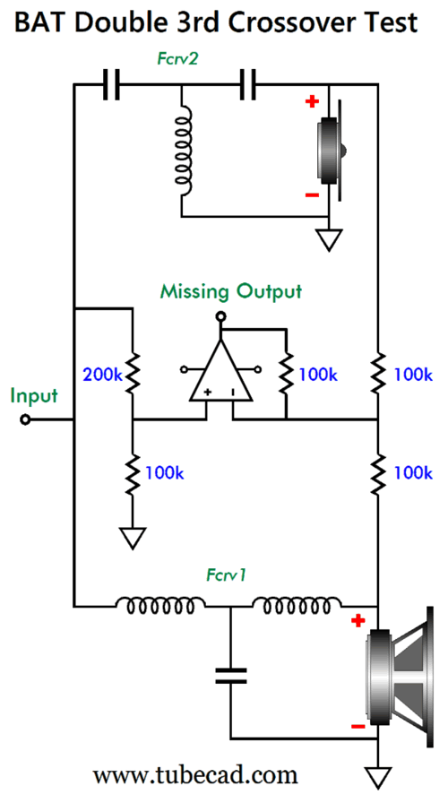
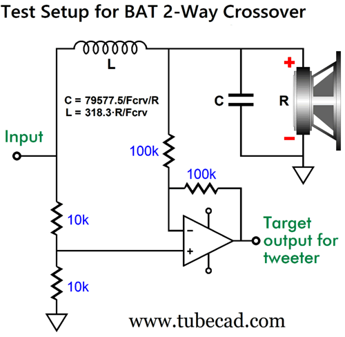
More BAT Phase-Flat Crossovers Now, the secret to my staggering topological fecundity is that each new idea, which can be either a new circuit topology or a new design technique, begets more new ideas, which in turn give rise to other new ideas. An example was my use of a difference amplifier to find the needed target frequency and phase plots to create what the midrange driver's frequency plot and phase plot would need to be, with 3rd-order woofer and tweeter filters, to establish both a flat frequency response and flat phase response when all three drivers were summed. The missing output delivered a target for me to hit with passive components; actually, two targets: a phase plot and a frequency plot.
I decided to use this technique of finding the needed output and then designing the passive network that delivers that output to a 2nd-order high-pass filter two-way passive loudspeaker crossover. SPICE simulations make this an easy, well relatively easy, task. The tweeter sees a 2nd-order high-pass filter with a Q of 0.5 (i.e. the same as Yamanaka and Linkwitz-Riley).
The target output from the OpAmp-based differential amplifier reveals what the woofer needs to contribute to the combined output to deliver both a flat phase and flat frequency response.
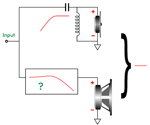
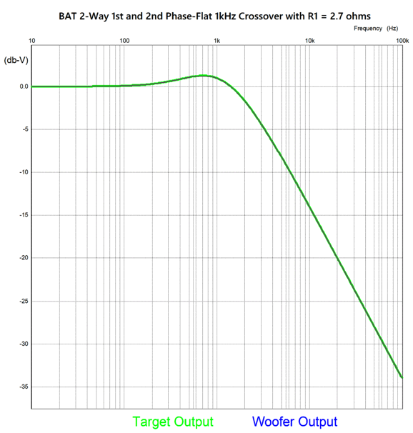
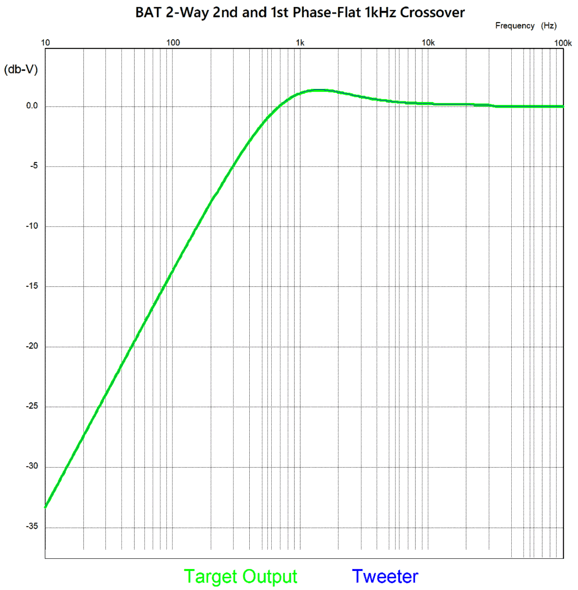
All I had to do was contrive a passive network (i.e. some combination of capacitors, inductors, and resistors) to deliver the woofer's needed signal. Since the needed output contained a hump, I knew that that the network must entail an insertion loss of a few dB, which could be cancelled by using a higher SPL woofer relative to the tweeter and by inserting a series resistor. Here is the target frequency response for a 1kHz crossover and my attempt at hitting it.
According to my mathematical analysis, the resistor's value needed to provide the optimum insertion loss is equal to 8 ohms divided by 3, or 2.666… Thus, I used a 2.7-ohm resistor in my SPICE simulations, as it is the closest readily available resistor value. I hit the required frequency response, but this is not enough as I had to also hit the phase plot. Fortunately, if I hit one target, I also hit the other target.
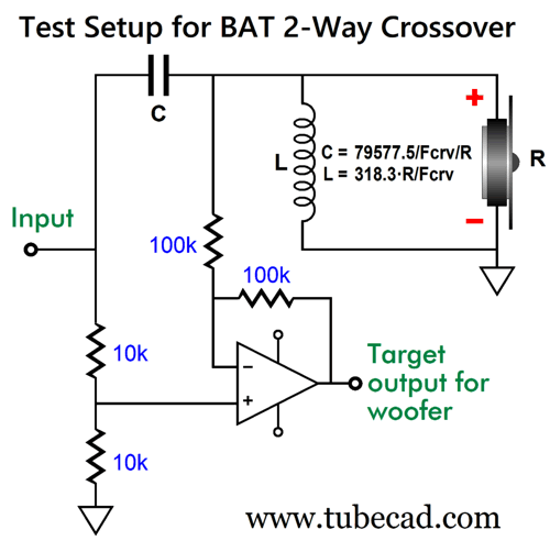
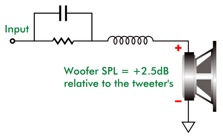
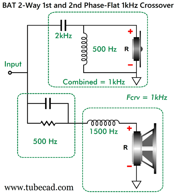
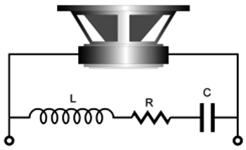
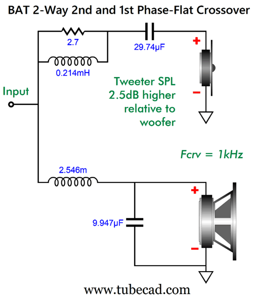
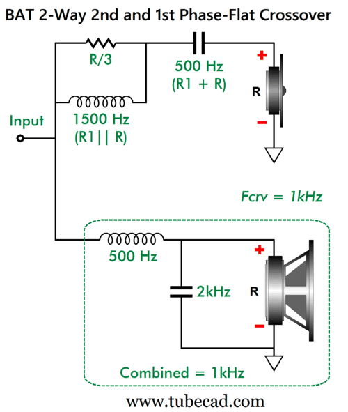
Now for the big reveal, the passive network that delivered the needed frequency and phase plots is the following:
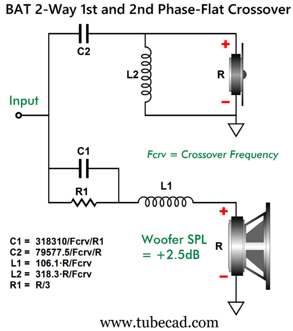
Low-frequencies down to DC are attenuated due to the resistor and the woofer defining a two-resistor voltage divider. At high-frequencies, the capacitor shunts the resistor boosting the highs until the inductor imposes a 1st-order low-pass filter. This is how we get our needed frequency hump. Of course, the capacitor, inductor, and resistor values are critical. Fortunately, I have gift wrapped it for you:
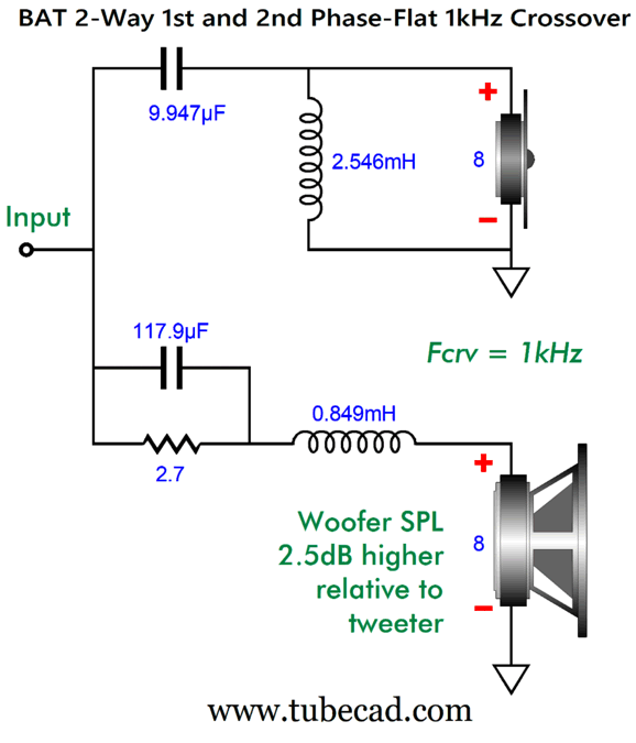
By the way, do not restrict your mind to the notion that only woofers and tweeters are used in a two-way loudspeaker system, as we could use a woofer with a fullrange driver or a horn whose low-frequency response extended down deep into the midrange frequencies. In addition, bear in mind that resistor R1 will decrease the woofer's Qes, as the resistor is in series with the woofer at low-frequencies. This is only a problem if we failed to acknowledge it and fail to incorporate it in our calculations. In fact, it could prove a feature in a dipole loudspeaker, as most woofers are too damped for effective dipole loading, resulting in a pinched bass response. Here is a 1kHz design example:
Of course, when actually building this crossover, we would use 10µF, 120µF, 2.5mH, 0.85mH part values. Actually, I take the last value, 0.85mH, back, as we can subtract the woofer's own internal series inductance (Le) from the 0.85mH value. The 2.7-ohm resistor must dissipate 25% of the heat that the woofer does at low-frequencies. In other words, think power resistor. I would use at least a 20W resistor with a 100W power amplifier, just to play it safe. (If your mind is as devious as mine, you realize that since the formula states that the resistor value must equal 1/3 that of the woofer, you could use three of the same woofer type in parallel, which could be located on the rear of a tall loudspeaker cabinet. Why? The three backfiring woofer would deliver two stunning attributes: canceling the single front firing woofers motions—see Newton's 3rd Law of motion—and undoing diffraction loss at low frequencies. The three woofers in parallel each see one third the current that the front-firing woofer sees, thus each produces one third the output of the front woofer. In other words, unity, as 1/3 x 3 = 1. The rear woofers present three times the mass of the front woofer, but only move one third as far as the front woofer. Once the signal frequency rises up to where the 117.9µF capacitor kicks in, the rear woofers' output drops off with 1st-order low-pass filter slope of -6dB per octave and -20dB per decade. In this example, the -3dB frequency is around 340Hz, which is just about perfect for undoing low-frequency diffraction-loss (aka baffle step response). If only I were a patent attorney. This brings up an interesting aspect of this BAT phase-flat crossover, namely at what frequencies are the reactive parts (the capacitors and inductors) tuned?
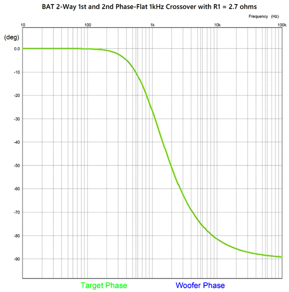
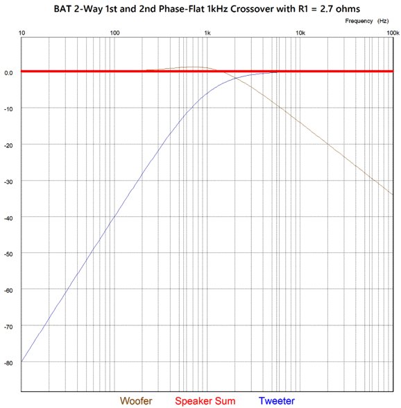
The crossover frequency is 1kHz, but none are tuned at 1kHz—however, all are tuned relative to the crossover frequency. Well, the important question to ask is how well does this new crossover work? Very well indeed.
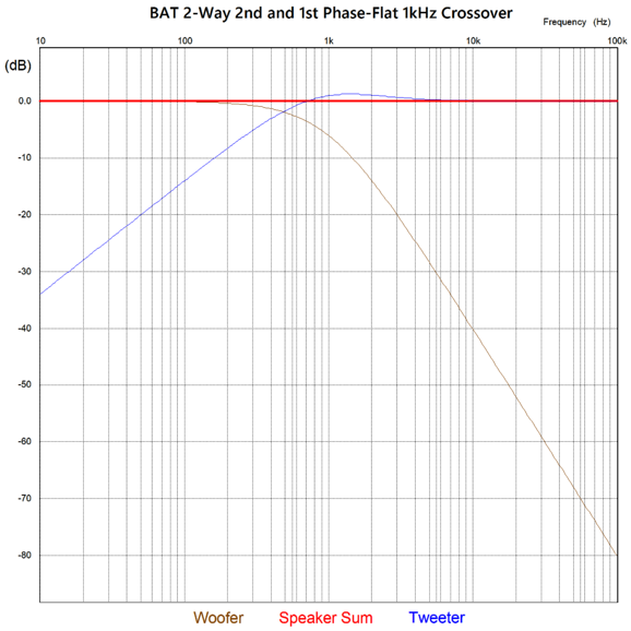
Since all loudspeaker frequency response plotlines look good with 10dB vertical decrements, we must examine the close up.
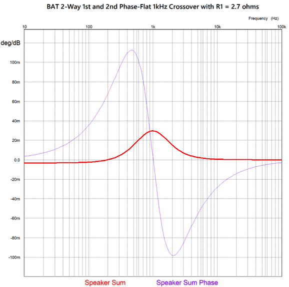
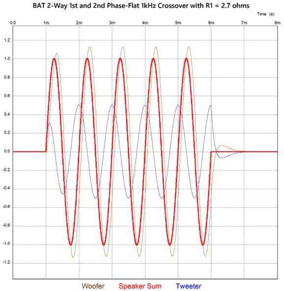
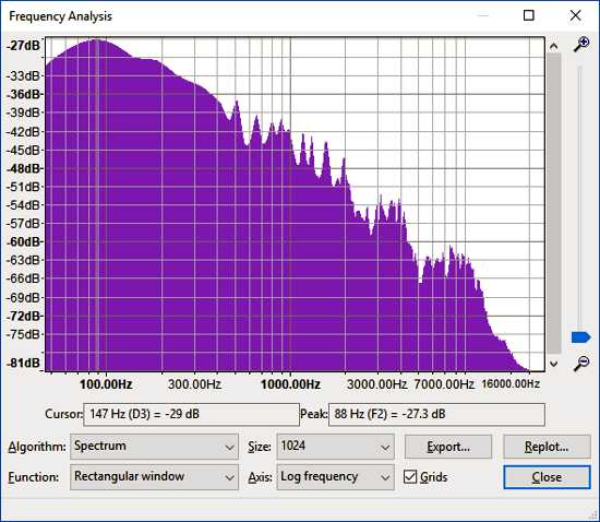
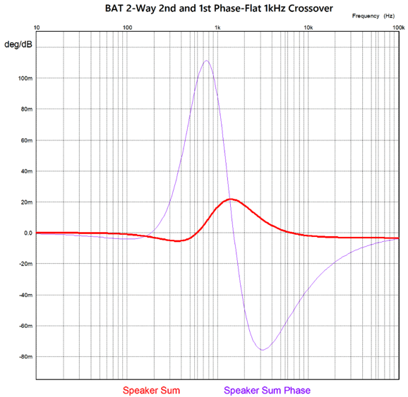
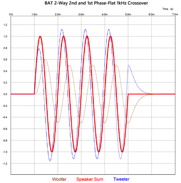
Not only is this not bad, it's crazy good. The frequency response deviates by only 30 millibells! The phase response is close to ±0.1 degree from 10Hz to 100kHz. Bear in mind, if I had used a 2.666… ohm resistor, the plot lines would be flatter still. Next, we see a four-cycle 1kHz tone burst (the hardest test for any loudspeaker to pass).
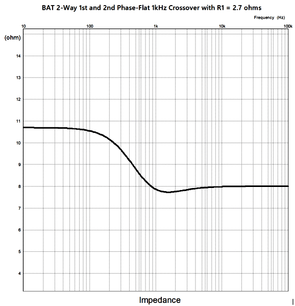
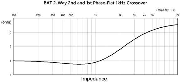
Okay, is this novel crossover perfect? No crossover is perfect. As I see it, the biggest potential issue is that the impedance plotline is not flat.
Well, at least the impedance doesn't dip too much. If an OTL power amplifier drives this loudspeaker impedance, we win, as OTL tube-based amplifiers are current-limited, not voltage-limited. Most of the energy in recorded music is found below 600Hz, so the OTL power amplifier can swing higher voltage into the higher impedance just where it matters most: the bass.
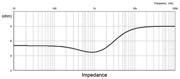
In contrast, solid-state power amplifiers are voltage-limited, not current-limited, which put the solid-state amplifier at a disadvantage with the higher impedance at low frequencies, as it can deliver fewer watts into the higher impedance. One possible workaround would be to use a 4-ohm woofer with an 8-ohm tweeter, which would result in lower impedance at low frequencies.
Not a bad load for a solid-state power amplifier, as the impedance does not dip below 4 ohms. We could use two 8-ohm woofers in parallel in place of a single 4-ohm driver, which would help in gaining the needed 2.5Db higher SPL per watt and would allow for an easy D'Appolito (MTM) arrangement, with the tweeter in the center of the two woofers. (The 2.7-ohm crossover resistor would be replaced with a 1-ohm resistor in series with a 0.33-ohm resistor.) Imagine a fullrange driver between two woofers with a crossover frequency of 400Hz. I would love to hear it. Keep in mind that in SPICE simulations resistors were used in place of loudspeaker drivers. Real speaker drivers, with the possible exception of planar drivers, present true horror-show impedance plotlines. In fact, I recommend using a "series-notch filter" network across the woofer leads, which will undo the impedance at the woofer's resonant frequency. Sadly, such a network often requires huge capacitor and inductor values.
What will complicate the situation is that the crossover's series resistor will increase the woofers Qes and Re, which are variables in the network's equation—or maybe not, as the network appears after the series resistor. What if we want to give the woofer the 2nd-order low-pass filter instead, thereby forcing the tweeter (or fullrange to perform the phase correction? I assumed that it would be a simple inversion of the formulas. It wasn't. I started with my test-bed setup with a differential amplifier to find the needed tweeter output.
Once again, output from the OpAmp-based differential amplifier reveals what the tweeter needs to put out in addition to the woofer's output to deliver both a flat phase and flat frequency response. Here is the needed target plot in green and my attempt to meet it in blue.
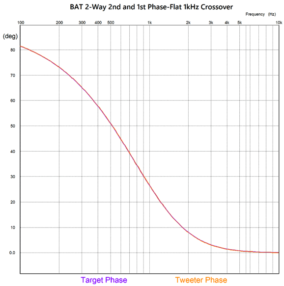
Next, the required phase plot.
Note how the phase swings positive at low frequencies, in contrast with the previous phase target that swung negative with high-frequencies. Here is the schematic and the needed math.
Here are the frequencies at which the reactive parts are tuned.
Note how the same frequencies appear as before, but differently located; in fact, inverted. How well does this new crossover work?
Once again, we do a zoom in at the crossover frequency of 1kHz.
This is crazy good, which explains how the crossover passes a tone burst without distortion.
Note that four cycles go in ad four come up. Also note that both the woofer and tweeter continue moving after the termination of the input signal, but their summed output cancels. This is transient-perfect reproduction on display. The graph remaining is the impedance plotline.
Active-Passive Crossovers
Here is the explanation from that post on what is going on here:
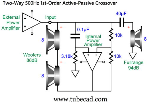
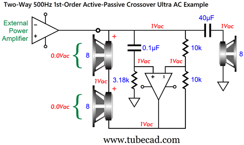
I had two goals in this design: I wanted to emulate the electrostatic Quad 57 dipole loudspeaker by using a 500Hz crossover frequency and two bass drivers and one high-frequency driver in the middle; and I wanted to give the bass output a 6dB boost relative to the fullrange driver, while still retaining the loudspeaker's nominal 8-ohm impedance. An added bonus was no crossover inductor, which are expensive and introduce DCR. Actually, I do not believe that power amplifier's damping factor is all that important; period. Many, however, do believe it is critical, so losing the series inductor is real bonus. Even the $107 Jantzen Audio 10mH 14 AWG C-coil toroidal crossover inductor presents 0.102 ohms of DC resistance, while the $92 air-core 1.2mH 14 AWG copper-foil tape inductor imposes 0.293 ohms of series resistance, which will reduce a solid-state power amplifier's damping ratio from something like 400 to 27. To see how this setup works, we must realize that the two woofers are intrinsically differential devices. If we apply the same voltage to both driver terminals, we get zero cone movement—even if that voltage is 100V. On the other hand, if we apply 99V to one terminal and 100V to the other, the driver sees a 1V difference and the cone move accordingly. Let's look into this differential functioning in detail.
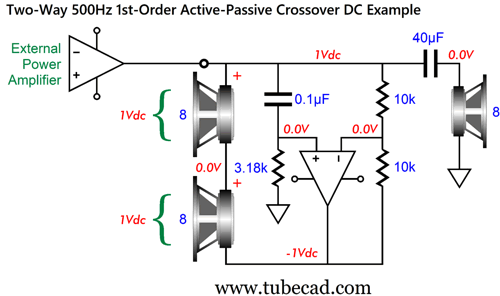
Each woofer sees the differential voltage as the other, so their net SPL is 6dB higher, which brings their combine output up to that of the fullrange driver. If the external power amplifier puts out a DC voltage, the following voltage relationships occur:
The 40µF crossover capacitor blocks the DC voltage to the fullrange driver. The internal power amplifier inverts the +1V into -1V. Next, we examine a high-frequency signal leaving the external power amplifier. The 0.1µF and 40µF capacitors pass the high-frequency AC signal, and the internal power amplifier no longer inverts the external amplifier's output signal.
Since the two woofers see the same in-phase signal voltage on both their terminals, they ignore it. In order for this active-passive setup to work, the internal power amplifier must be able to deal as much power as the external power amplifier. The assumption here has been that a relatively low-power tube-based external power amplifier would be used. Since modern class-D power amplifiers are both powerful and cheap, probably less expensive than a high-end woofer inductor, we can force this arrangement to work with 200W solid-state external power amplifiers. In Post 585, I also show a version that gives the tweeter a 2nd-order high-pass filter.
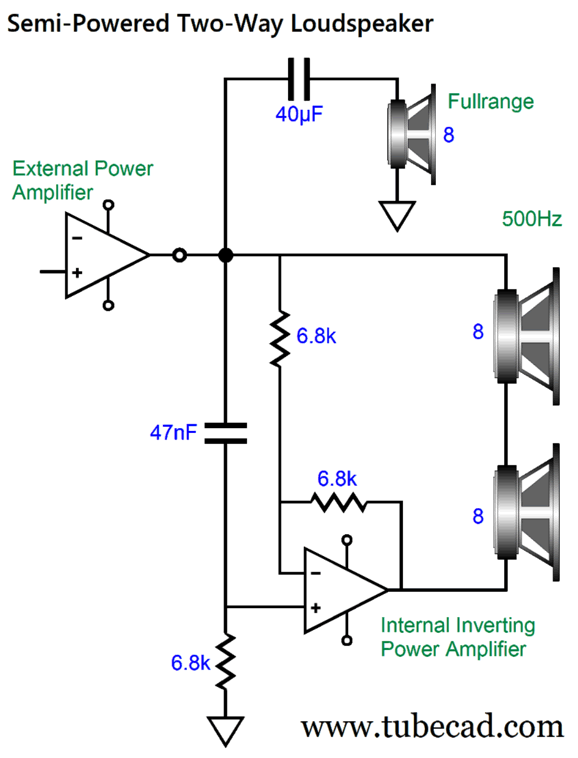
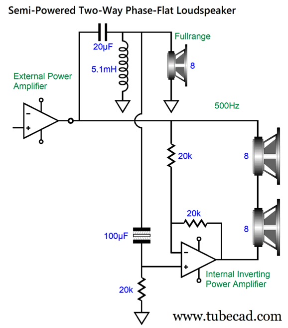
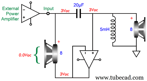
I wondered what a version would look like that used a single 8-ohm woofer. No internal power amplifier phase inversion would be needed, but the internal amplifier would still have to deliver the same amount of power as the external power amplifier. The woofer will see a slightly bigger voltage swing near the crossover frequency due to the phase difference between the two amplifiers' output.
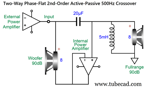
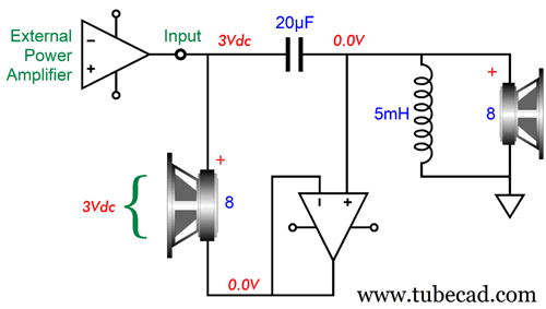
The internal power amplifier has been replaced by a unity-gain power buffer. Only two crossover parts are needed, the 20 µF capacitor and 5mH inductor. As a proxy for low-frequencies, we start with 3Vdc leaving the external power amplifier.
The unity-gain power buffer acts as a virtual ground and must absorb all the current flow through the woofer, i.e. 3V/8 or 0.375A. Next, we examine the high-frequency AC example.
The unity-gain power buffer passes on the AC signal that the tweeter sees in phase. Since the woofer sees the same in-phase AC signal voltage on both its terminals, it ignores it. How well does this setup work?
Next Time: 3-Way BAT
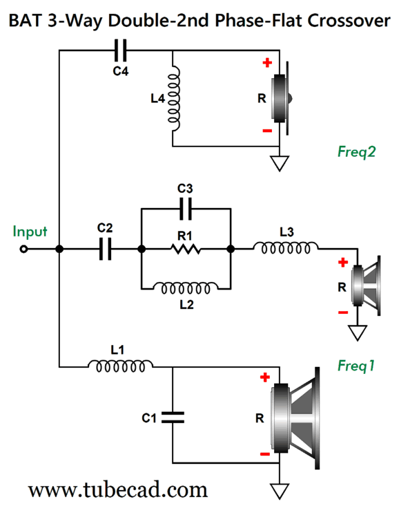
Next, we see a design example:
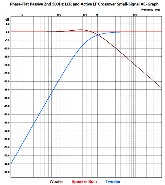
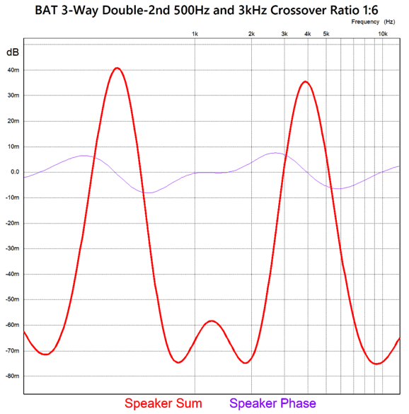
The crossover frequencies are 500Hz and 3kHz. In this example, the midrange driver must be 2.7dB more efficient in SPL than the woofer or tweeter. How close did I come to hitting my two targets, flat frequency response and flat phase? Dang Close.
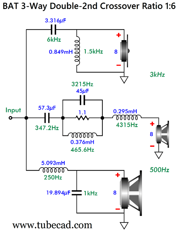
Of course, the phase plot is in degrees. To be flat within ±0.01 degrees is stunning. Moreover, a speaker that is frequency flat within ±3dB is considered very flat. If it were flat within ±0.06dB, we would have to come up with a new metaphor, as rulers are not that flat. The problem with this crossover design is that I haven't been able to come up with the neat formulas as I had done so with the previous two-way design. (Math is a young man's game, alas. I am way past my math prime.) Instead, I came up with an array of crossover frequency ratios. For example, this design example holds a ratio of 1 to 6, which 200Hz and 1.2kHz also conforms to, as does 600Hz and 3.6kHz. The 1.1-ohm resistor remains constant, but all the other parts must be altered by a 500Hz/200Hz ratio in the first case and by a 500Hz/600Hz ratio in the second case. In other words, if we wanted the 200Hz and 1.2kHz crossover frequencies, we would multiply all the capacitor and inductor values by 500/200 or 5/2 or 2.5, leaving the 1.1-ohm resistor in place; the 600Hz and 3.6kHz crossover, by 500/600 or 5/6 or 0.8333. This procedure might qualify as "gift wrapped," just without the fancy bow. In my next post, I will display a table of part values and ratios.
Music Recommendation: Kodo's Mondo Head Mickey Hart, of Grateful Dead and world-music and "Dafos" fame, produced this 2002 album, which goes a long way to explaining the captured sonic magic. Beyond deep stomach-punching bass, the stereo imaging is spectacular. I understand that the SACD of the album must be heard to be believed. Nonetheless, the CD is amazing. (Considering that I bought this CD at a garage sale for a dollar, the sonic splendor per penny is insane.) I just found today that Qobuz sells a 24-bit, 96kHz download version of the album, which I just bought for about $18—that in its self constitutes a big recommendation from me.
//JRB PS
I am impressed. How long before AI can rewrite my post in Japanese or French or German? I am sure it can do now, but I wouldn't trust it. Next year? Maybe.
Did you enjoy my post? Do you want to see me make it to post 1,000? If so, think about supporting me at Patreon.
User Guides for GlassWare Software
For those of you who still have old computers running Windows XP (32-bit) or any other Windows 32-bit OS, I have setup the download availability of my old old standards: Tube CAD, SE Amp CAD, and Audio Gadgets. The downloads are at the GlassWare-Yahoo store and the price is only $9.95 for each program. So many have asked that I had to do it. WARNING: THESE THREE PROGRAMS WILL NOT RUN UNDER VISTA 64-Bit or WINDOWS 7, 8, and 10 if the OS is not 32-bit or if it is a 64-bit OS. I do plan on remaking all of these programs into 64-bit versions, but it will be a huge ordeal, as programming requires vast chunks of noise-free time, something very rare with children running about. Ideally, I would love to come out with versions that run on iPads and Android-OS tablets.
|
I know that some readers wish to avoid Patreon, so here is a PayPal button instead. Thanks. John Broskie
John Gives
Special Thanks to the Special 95! To all my patrons, all 95 of them, thank you all again. I want to especially thank
I am truly stunned and appreciative of their support. In addition I want to thank the following patrons:
All of your support makes a big difference. I would love to arrive at the point where creating my posts was my top priority of the day, not something that I have to steal time from other obligations to do. The more support I get, the higher up these posts move up in deserving attention.
If you have been reading my posts, you know that my lifetime goal is reaching post number one thousand. I have 376 more to go. My second goal was to gather 1,000 patrons. Well, that no longer seems possible to me, so I will shoot for a mighty 100 instead. Thus, I have just 5 patrons to go. Help me get there. Thanks.
New URL of the GlassWare website |
||||


| www.tubecad.com Copyright © 1999-2025 GlassWare All Rights Reserved |