| John Broskie's Guide to Tube Circuit Analysis & Design |
31 October 2021 Post Number 547
Happy Halloween
Costruire HiFi
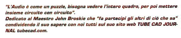
Thus, the dedication to me:
I like the sound of "Maestro," but it only means teacher or instructor in Italian. To be honest, what I liked best was reading the editorial by Andrea Bassanelli, titled, "Male or Female, Enough Polemics" (Controversy). In the original Italian: Maschio o femmina? Basta Polemiche... Apparently the Professional Audio Manufacturers Alliance has decreed that we must categorically no longer refer to "male" and "female" electrical connectors. Why? Obviously, the feelings of right-thinking audiophiles and the electrical components were being hurt, as PAMA puts it:
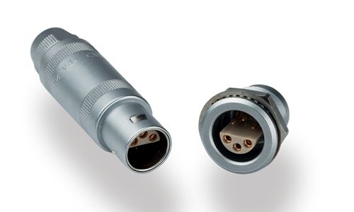
Yes, yes, yes—finally, we are making an advance in audio equity and connector justice. Long have I thought the best solution is to adopt an epicene, hermaphroditic connector, such as the Lemo S-Series type, which includes both prongs and apertures. Say goodbye to cisgender connectors. Say hello to a bright post-patch-cord-patriarchal future.
Well, I have long suspected that a few of the RCA jacks on the back of my line-stage amplifier were distinctly non-heteronormative, possibly non-binary or gender fluid but decidedly not agenda, so I took to referring to them as RCA janes, but they still felt unheard and slighted, as was evident from the way connector with an extended prong continually fell out of these connectors with an aperture. The solution was found in placing another RCA connector with an aperture intimately next to each other, although the resulting sound level, for some unfathomable reason, was extremely attenuated. Sadly, Mr. Bassanelli is likely to continue dead-naming these poor RCA connectors with an aperture, as his editorial uses such pain-inducing words as "female," "folly," "male," "useless," "demented," and he claims that this important advancement in morality and appropriateness in regarding power relations between individuals, which he slanderously refers to as "political correctness," make him want to vomit. Yes, vomit! In Italian, vomitare. Does he not realize that we are on the threshold of a new dawn of a higher-evolved civilization, resplendent with unbounded equality and enforced harmony and inclusivity, which only requires that we all accept and abide by a few simple precepts, guidelines, dictums, injunctions, universal rules, commandments, federal and international regulations, mandated manners, ethical edicts, local ordinances, instructions and pronouncements from those individuals freed from ignorance and misinformation, say Hollywood stars, TikTok luminaries, Top-Forty singers, enlightened Silicon Valley oligarchs, and academics whose field of study ends in "studies"? So little to ask, so much to gain. We are talking about meaningful change here, not just plain change, but meaningful change. Just do and believe what you are told—how hard can that be? Italy, Italy, what have you wrought? I, for one, will henceforth boycott Ferrari and Maserati cars. Trust me, you won't catch me driving a Ferrari 812 GTS or Maserati MC30. Perhaps our state department could send someone, preferably wearing a stern and somber pantsuit, to the UN to denounce Italy. Lest you consider this act too belligerent, I left the worst for last. Mr. Bassanelli even went so far as to preface his hate-filled screed with a quote from Charles Bukowski:
Returning to the land of reality, I want you to try to imagine any editor of an American audio magazine doing the same. You can't do it—nor can I, sadly.
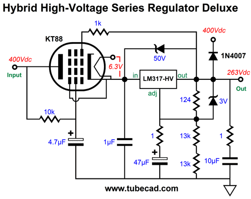
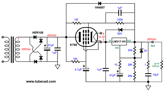
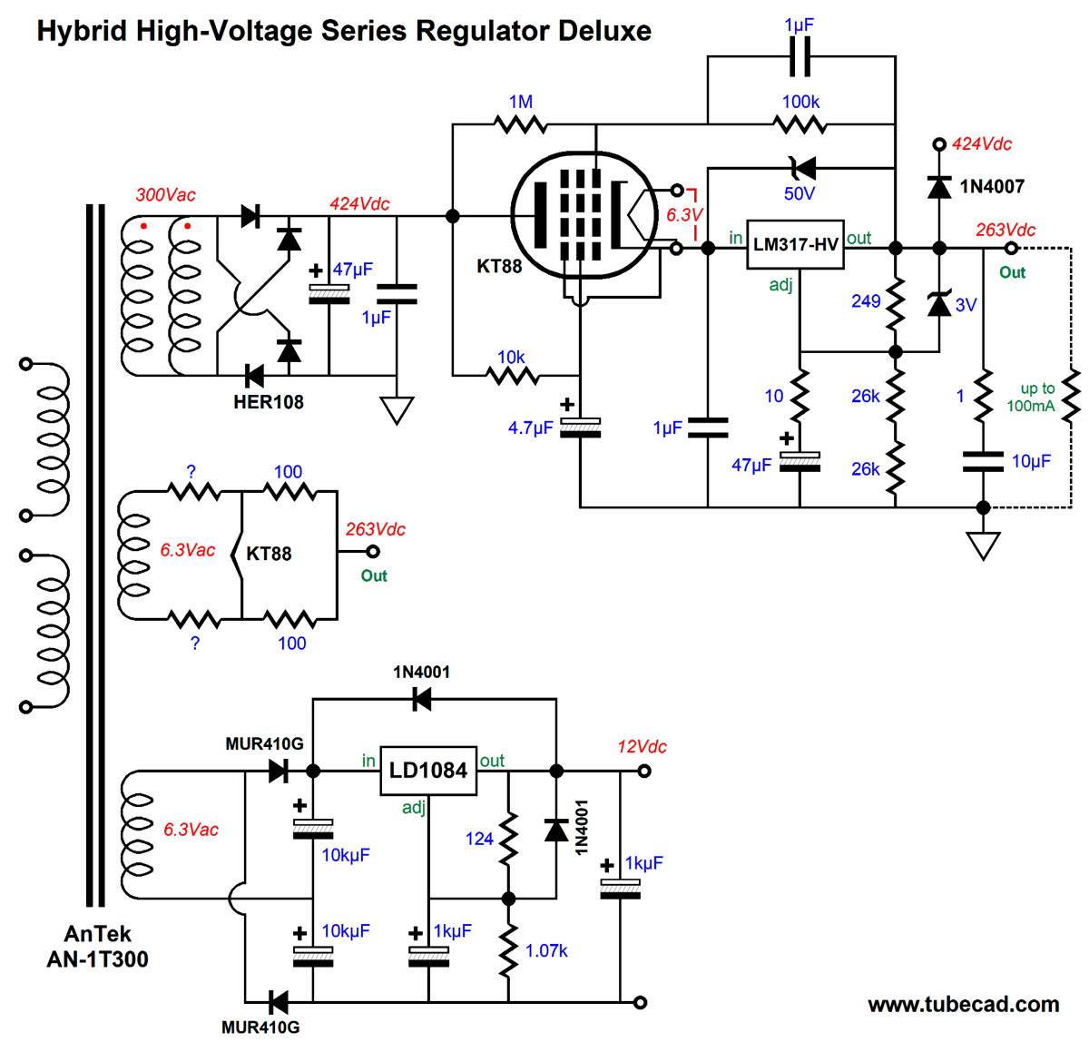
KT88 and LM317-HV Regulator This hybrid design allows us to use a relatively low-voltage regulator in an otherwise high-voltage regulator. In addition, the tube's slow warm-up time makes for a slow ramping up of the output voltage and a vacuum tube is far more likely to survive an accidental shorting of the output to ground. Okay, that is the plus side, but the minus side isn't empty. Tubes wear out and cost far more than high-voltage MOSFETs. Moreover, they hold a heater element that must be powered and incur relatively huge voltage drops, whereas MOSFETs do not, which means a lot of wasted heat. The required cathode-to-plate voltage had me worried, so I assembled the following circuit in SPICE.
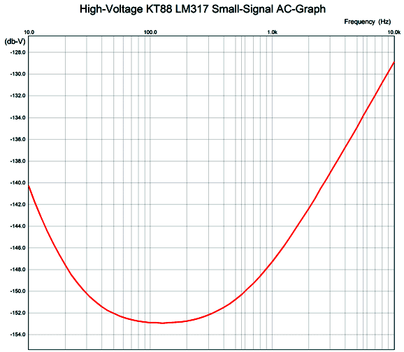
At idle, with no external load, the solid-state regulator draws just 5mA. The PSRR versus frequency plot-line is excellent, as in crazy good.
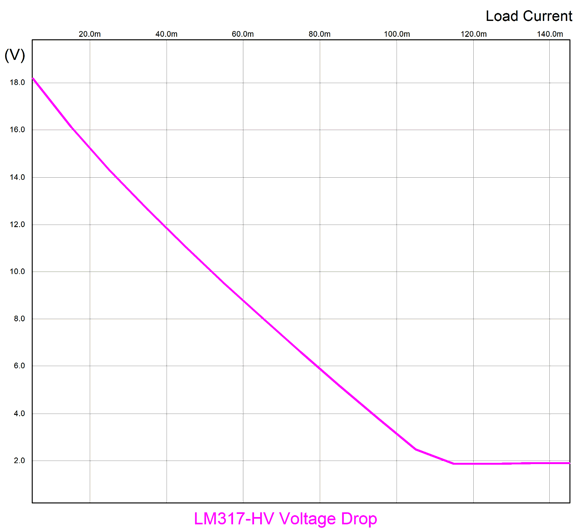
The LM317-HV 3-pin, adjustable regulator needs to see at least a 2V voltage drop from its input to its output, with 3 volts a safer bet. Here is the SPICE-generated graph that shows the voltage differential versus the external load current.
We can see that at about 110mA, the regulator saturates and ceases to maintain regulation. A reasonable limit would be 100mA. At idle the voltage drop is 19Vdc, well below the regulator's voltage limit. Even with a wall-voltage overage of 10%, the raw B+ voltage rising to 464Vdc, the voltage drop is only 24Vdc. In other words, it looks like we can get away with using just an LM317. (I would still use the LM317-HV, as high-voltages and solid-state devices make me nervous.) In addition, I believe most KT88 tubes are rated for 140mA of continuous current flow, so 100mA is a good limit to observe. At the other extreme, where the wall voltage droops by 10%, we run into a lower current limit, as in 60mA max into the external load. Why? The KT88 is starved of cathode-to-plate voltage. Here is a possible workaround.
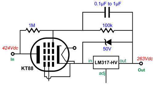
The added two resistors in series form a two-resistor voltage divider that delivers 9% of the voltage differential between the raw B+ voltage and the output voltage to the grid. The capacitor shunting the 10k resistor relays the clean AC signal from the regulator's output to the grid. With these three added parts in place, the regulator can deliver 100mA even with a 10% reduction in the raw B+ voltage. What about at the other extreme, wherein the raw B+ voltage climbs by 10% and no external load is attached, will the solid-state regulator still be safe. Yes, it will, as the voltage drop across it rises to only 42Vdc (here is where the LM317-HV comes in handy, with its 57V voltage limit). What about the KT88, will its maximum plate dissipation be exceeded? No, as 21W is far below its 42W limit.
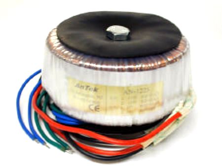
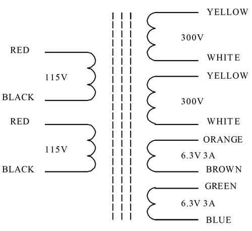
The assumption here is that a 300Vac or a 600Vac-CT transformer will power the regulator. The one I had in mind is made by An-Tek, model AN-1T300, a 100VA toroid. The transformer holds two 300Vac @ 100mA secondaries and two 6.3Vac @ 3A secondaries.
The two high-voltage secondaries can be placed in series to create a center-tap and use two-rectifier full-wave rectification. Or, they could be placed in parallel and use four-rectifiers. Both arrangements will yield the 424Vdc of raw B+ voltage.
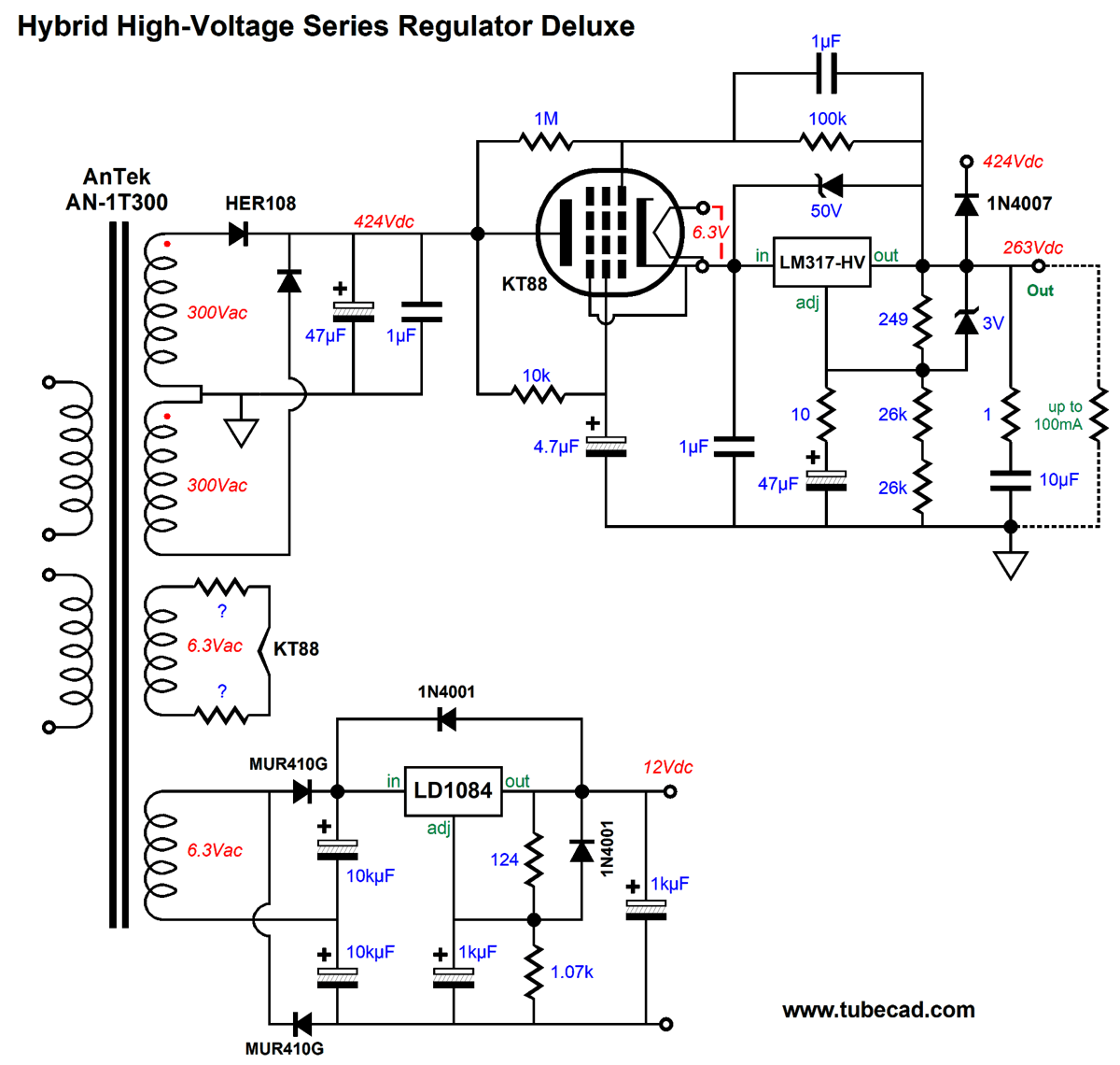
One of the 6.3Vac secondaries can power the KT88 heater element, while the other can power the audio circuitry heaters. Here is one possible setup.
All the secondaries are used. The bottommost secondary is configured for voltage-doubling rectification; thus, the 6.3Vac develops about 16Vdc of raw DC voltage for the LD1084 LDO regulator. The strict math informs us that about 800mA is all that his regulator can deliver. Reality, however, will prove more generous, as we are under-taxing the other secondaries. In addition, the toroid was built to handle 50Hz wall voltages, so when used with 60Hz AC, the VA rating goes up by 60/50 or 20% or 120VA. The two mystery resistors that attach to the KT88 heater element are there to tweak the AC voltage. Note that the two primaries are designated for 115Vac, which works great if your wall voltage is either 115Vac or 230Vac, but not if it is closer to 122Vac, as was the case at one house that I lived in years ago. With the hot 122Vac wall voltage, the heater would see at least 6.7Vac. Moreover, the KT88 heater draws 1.6A to 1.8A of current, while the secondary is rated for 3A. In other words, we get a further voltage boost, possibly bringing the voltage up to 7Vac or more. Adding the two resistors will limit the voltage to 6.3Vac and provide a softer current inrush, as the cold heater element's cold resistance is far lower than its hot resistance. Two 0.22-ohm 1W or 2W power resistors will probably do the job. Here is the same regulator, but with full-wave bridge rectification.
Note the added 100-ohm resistors attached to the KT88's heater. They might improve the hum rejection, as they effectively center-tap the heater winding. I love the look of it, and I can easily picture a KT88 majestically seated on the PCB. In other words, I am sorely tempted to make a PCB based ont he circuit shown above.
Patent US 8,995,697: Bipolar Speaker with Improved Clarity
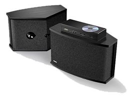
In contrast, the bipole speaker also radiates sound forward and backwards, but the rear radiation is in phase with the front radiation. The famous Bose 901 loudspeaker is a bipole, as it holds front and rear speaker drivers. But according to this patent, Bose got the ratios wrong.
The 901 loudspeaker's rear radiation is +18dB greater than the front radiation, whereas the patent stipulates that the rear radiation must be -6dB lower than the front to sound good. Is this true? It must be, as the US Patent Office vouchsafes it. Never forget that Albert Einstein was a patent clerk and that he was not even a technical expert Class-1, but only a Class-2 expert. Imagine how smart the Class-1 experts must have been.
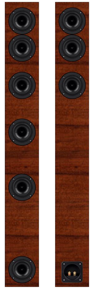
Okay, enough of my patent-system cynicism. Let's assume that having the rear radiation being half of the front's is the right ratio. This means that the Bose 901 loudspeaker should have placed six drivers on the front and three on the rear, as that would have resulted in the 2:1 ratio. I can imagine a thin, tall speaker enclosure that held the front six drivers in a vertical line, with three other drivers on the backside. Using 8-ohm fullrange drivers, the speaker impedance would still be 8 ohms, but the total SPL would increase by 9.5dB. To avoid repeated interference and lobing effects, the drivers could be spaced apart with increasing prime numbers; for example, 5", 7", 11", 13", 17" apart. Of course, we could add tweeters, but we wouldn't need nine of them, as two would be enough, one for the front and one for the back, with the backside tweeter padded by -6dB. Such a loudspeaker just might sound amazing. If nothing else, the rear radiation would undo the low-frequency diffraction loss. Front Returning to the patent, as patents go, it isn't that hard to read. In fact, I recommend that you at least give it a scan, as it does provide a good overview of the problems of making a loudspeaker sound good in a living room. One tiny quibble I have is that I believe the patent's writer has mistook "object" for "objective," as we do have objects of desire and of study and of investigations, which sounds like the overarching subject, whereas "objective" denotes the desired aim, goal intention, and purpose of our efforts. The object of playing a game of basketball is to win, while at least two of the player's objectives are to put the ball through the opponent's hoop and to prevent them from doing the same to your basket. The dictionary explicates the distinction thus:
We would hope that a patent had attained some tangible improvement. But then, only a mad man would argue with a lawyer. Here is its description of the invention:
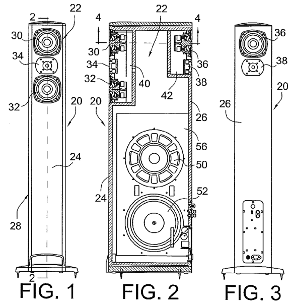
That's some spread of acceptable ratios: -2.5dB, -6dB, -8dB, -9.5dB—followed by the limitless "etc." Apparently, as long as the rear radiation is less than the front radiation, things are good. I am sure what this means is that it depends; it depends on the music played back; it depends on your room size and reflectivity of the walls; and it depends on the speaker's distance from the rear wall. The way patent establishes the 2:1 radiation output is to use two midranges on the from and one in the back, along with two tweeters, one in between the two front midranges, in the MTM or D'Appolito arrangement, while the rear tweeter sits above the rear midrange. The low frequencies are covered by powered woofers, whose output is omnidirectional.
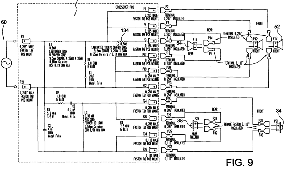
If we are using 8-ohm midranges, won't the impedance fall to 2.66 ohms, as that is what we get with three parallel 8-ohm resistances? The workaround would be to use 24-ohm midranges, which in parallel yield 8 ohms. The tweeters could be 16-ohm types, with the rear tweeter getting a -6dB padding network made up of 16-ohm and 8-ohm resistors. Here is the crossover shown in the patent.
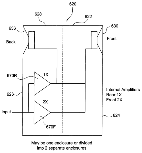
Note that the driver impedances are not specified, nor could I find any mention of them in the patent. The patent did state that if internal power amplifiers were used within the loudspeaker, the amplifier driving the front drivers would offer twice the gain (+6dB) of the rear power amplifier.
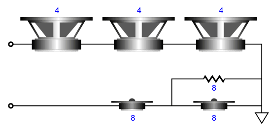
This arrangement would allow us to use the same number of drivers on the front and rear; in other words, two woofers and two tweeters. With such a setup, we could do some easy experimenting. For example, would four loudspeaker enclosures work as well or better than two? What if we took four identical small speakers and place two behind the main speakers, but positioned at least three feet behind and facing the wall? This way we have introduced a time delay between the speakers, but reduced the delay from the reflected sound from the back wall. By using two stereo power amplifiers, we could adjust the output to the rear speakers. Moreover, we could move the rear speaker about, further away or closer, twisting and tilting as needed . In other words, we could play with many variables, possibly arriving at the best sound possible in our listening room, but not necessarily in anyone else's listening room. Never forget that your listening room is the biggest and worst component in your sound system. I have heard identical stereo gear sing and cry in different rooms, just as I have heard string quartets sound greatly different in different venues. Assuming that the patent got things right, how else could we arrive at the same 2:1 sound radiation? Well, what about using three 4-ohm woofers and two 8-ohm tweeters? The three woofers in series yield an impedance of 12 ohms. Placing both tweeters in series, with one tweeter shunted by an 8-ohm resistor, also yields a 12-ohm impedance.
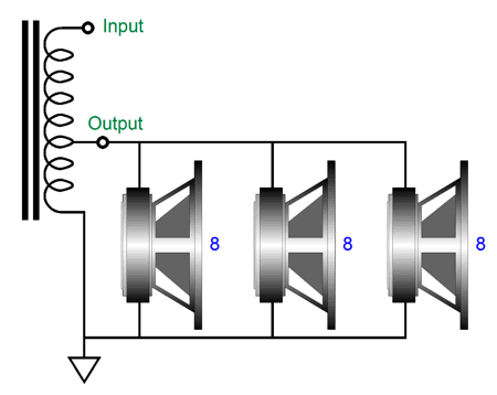
We would use the same MTM arrangement for the front and the woofer-tweeter arrangement for the rear as the patent. If nothing else, the 12-ohm impedance would make OTL power amplifiers much happier. Indeed, it would make many solid-state power amplifiers happier. This might make a fun computer or bedroom loudspeaker. Actually, I would use three 4-inch woofers and two identical 3-inch or 4-inch fullranges instead of two tweeters for a small computer speaker. Why? Balanced sound. The small woofers cannot produce deep bass, so the highs should not extend too far. See post 404. Just as importantly, we could use a 1st-order crossover with a 500Hz crossover frequency. Mercy! We would get a balanced phase-flat response. Another possible arrangement would be to use three 8-ohm drivers and an autoformer.
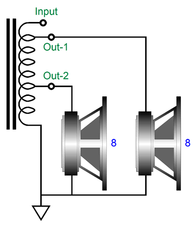
The three drivers in parallel create a 2.666-ohm load, which the autoformer magnifies to an 8-ohm impedance. In order to get the 1:3 impedance magnification the autoformer tap must appear at 57.7 percent of the winding. Why? An autoformer's impedance ratio is found by taking the inverse of the ratio and squaring it. For example, if the tap occurs exactly at half the winding, i.e. 50%, the tap is 0.5 of the winding, whose inverse equals 1/0.5 or 2; now, 2² equals 4; thus the impedance ratio is 1:4. If we attach an 8-ohm speaker driver to the tap and ground, the reflected impedance at the top of the autoformer's winding will be 32 ohms. Well with a tap at 0.577, the inverse is 1.732 and it squared equals 3; thus, the impedance ratio is 1:3. Since 0.577 is close to 0.6, we could lay down six layers of neatly wound wire, and then add a tap at the end of the layer, before continuing to lay down four additional layers. Connecting the 8-ohm drive to this tap results in something close to 8 ohms at the autoformer's input. Would this actually work? Let's do the math, but from a different angle. If we apply a 24Vpk sine wave to the top of the autoformer, the three parallel drivers will see 24 x 0.577 peak volts of signal or 13.85Vpk, which across an 8-ohm load equals 12W of power. Since we have three drivers and each gets 12W, the total wattage delivered is 36W. What would 24Vpk into one 8-ohm driver equal in watts? The formula for watts with sine waves is easy: Watts = Vpk ² / (2 x Resistance) or Watts = (Vpk²/ √2) / Resistance We plug in the values and we get 36W. All three drivers see the same amount of driving signal, but since the front two drivers offer twice the radiating surface area, their combined SPL is 6dB higher than the single driver in the rear. Lo and behold the glory of the inductive device. Twenty-four watts go in and twenty-four watts come out; 2.666 ohms appears as 8 ohms. All that was required was a chunk of iron and a few hundred feet of copper wire. What if we choose to forgo the MTM arrangement? Why would we? I, for one, find the MTM setup deeply suspect when used with high crossover frequencies, as the distance between drivers far exceeds the wavelength of the crossover frequency. In contrast, the original Quad electrostatic loudspeaker was a Woofer-Tweeter-Woofer effort, with a crossover at 500Hz, whose wavelength is 27 inches. This makes sense, whereas a crossover frequency of 5kHz doesn't due to the tiny 2.7 inch wavelength and 10 inch spacing between midranges. In other words, what if we want to use only two woofers and two tweeters? In this case, the autoformer could come to the rescue again. We want the rear drivers to put out half the radiation of the front drivers, which means that they must receive half the AC voltage that the front drivers get. In addition, we would like to use 8-ohm drivers and present an 8-ohm load to the power amplifier. Can it be done? My flash of intuition yelled out, "No problem, just add an additional tap to the autoformer." Actually making it work took some head scratching.
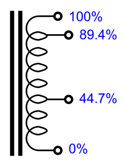
If the rear driver sees half the AC voltage, then it will receive one quarter the wattage that the front driver receives. Given 100W of power from the amplifier, the rear driver gets 20W, while the front driver gets 80W. To get 100W with an 8-ohm load requires 40Vpk; to get 80W, 35.78Vpk; and to get 20W, 17.9Vpk. To find the first autoformer tap, we divide 35.78 by 40 and get 0.894; thus, the first tap occurs at 89.4% of the autoformer winding. Since the rear driver must see half the voltage of the front driver, the second tap must be placed at 50% of the first tap or at 0.447 or 44.7%.
Will this work? Starting with the second tap, the impedance ratio equals (1/0.447)² or 1:5, which means that the 8-ohm rear driver will reflect as a 40-ohm load. Moving on to the first tap, we find the impedance ratio by (1/0.894)² or 1:1.25, which means that the 8-ohm front driver will reflect as a 10-ohm load. The next step is to place 10 and 40 ohms in parallel and we get 8 ohms, as 10||40 = 8 or (10 x 40)/(10 + 40) = 8. In other words, it works. How could we make one? I would lay down twenty layers of wire, with the first tap at the end of the 18th layer and the second tap at the end of the 9th layer. Since I fear high-frequency issues with the autoformer, I would forgo the autoformer and use two 4-ohm tweeters, but with a twist.
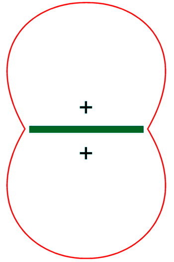
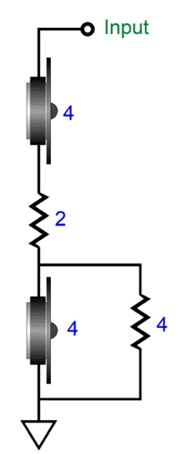
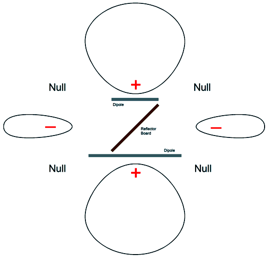
The load impedance is 8 ohms, but the rear tweeter is down 6dB relative to the front tweeter. I happen to prefer 4-ohm tweeters, when I can get away with them. Why? Better highs. How so? Compare the same tweeter in two impedances, 4 and 8 ohms. (Loudspeaker driver companies often offer the two impedances due to demands of the car-audio market.) The 4-ohm version uses half as much wire in its voicecoil, which mean less mass, which in turn means better highs. Ideally, I would love to see tweeters with impedances well below 1 ohm coupled to an air-core autoformer. Remember it’s the current flow through the voicecoil that makes the diaphragm move. Imagine a tweeter voicecoil with an impedance of 0.5 ohms coupled to an autoformer with a voltage ratio of 4:1, a current ratio of 1:4, and an impedance ratio of 1:16. The impedance at the top of the autoformer winding is 8 ohms, and the tweeter sees one fourth the voltage but four times the current flow. By the way, ribbon tweeters are often arranged this way, except that they use transformers, not autoformers. (The danger with either the autoformer or transformer coupling to the ribbon tweeter is that it cannot be directly coupled to a solid-state power amplifier in a bi-amped system, as the DC resistance presented is near zero, which any amount of DC offset, no matter how seemingly trivial, will cause huge headaches.) Could the 2:1 bipole radiation arrangement be applied to planar loudspeakers, such as electrostatic or Magnepan types? Maybe. First of all, electrostatic speakers do not have to be dipoles, as we could enclose the rear radiation in a box, for example, like the famous Beveridge electrostatic speakers. But if we did use dipoles, we could use two panels, one in front of the other, with the rear panel half the width of the front panel. Here is the top view.
The reflector board between diaphragms prevents the unwanted reflections between panels. Visually, the electrostatic panels would look the same as single panels, but the combined panels would take up a lot more space. Such an arrangement would prove far more stable, however, than a single panel, as the rocking back-and-forth motion of the single panel is eliminated. By the way, I recommend searching for all the patents by Definitive Technology, as it is an interesting company that truly strives to make the best loudspeakers. I know that their speakers are near universally deemed the best choice for home theater setups. I have never knowingly heard their loudspeakers in the typical audiophile stereo configuration, sadly. I know that Best Buy carries the line, so I just might have the chance.
Music Recommendation: Cyrus Chestnut's Kaleidoscope
//JRB
Did you enjoy my post? If so, think about supporting me at Patreon.
User Guides for GlassWare Software
For those of you who still have old computers running Windows XP (32-bit) or any other Windows 32-bit OS, I have setup the download availability of my old old standards: Tube CAD, SE Amp CAD, and Audio Gadgets. The downloads are at the GlassWare-Yahoo store and the price is only $9.95 for each program. http://glass-ware.stores.yahoo.net/adsoffromgla.html So many have asked that I had to do it. WARNING: THESE THREE PROGRAMS WILL NOT RUN UNDER VISTA 64-Bit or WINDOWS 7, 8, and 10 if the OS is not 32-bit or if it is a 64-bit OS. I do plan on remaking all of these programs into 64-bit versions, but it will be a huge ordeal, as programming requires vast chunks of noise-free time, something very rare with children running about. Ideally, I would love to come out with versions that run on iPads and Android-OS tablets.
|
I know that some readers wish to avoid Patreon, so here is a PayPal button instead. Thanks. John Broskie
John Gives
Special Thanks to the Special 90 To all my patrons, all 90 of them, thank you all again. I want to especially thank
I am truly stunned and appreciative of their support. In addition I want to thank the following patrons:
All of your support makes a big difference. I would love to arrive at the point where creating my posts was my top priority of the day, not something that I have to steal time from other obligations to do. The more support I get, the higher up these posts move up in deserving attention.
If you have been reading my posts, you know that my lifetime goal is reaching post number one thousand. I have 453 more to go. My second goal was to gather 1,000 patrons. Well, that no longer seems possible to me, so I will shoot for a mighty 100 instead. Thus, I have just 10 patrons to go. Help me get there. Thanks.
Support the Tube CAD Journal & get an extremely powerful push-pull tube-amplifier simulator for TCJ Push-Pull Calculator
TCJ PPC Version 2 Improvements Rebuilt simulation engine *User definable
Download or CD ROM For more information, please visit our Web site : To purchase, please visit our Yahoo Store: |
|||


 Rear
Rear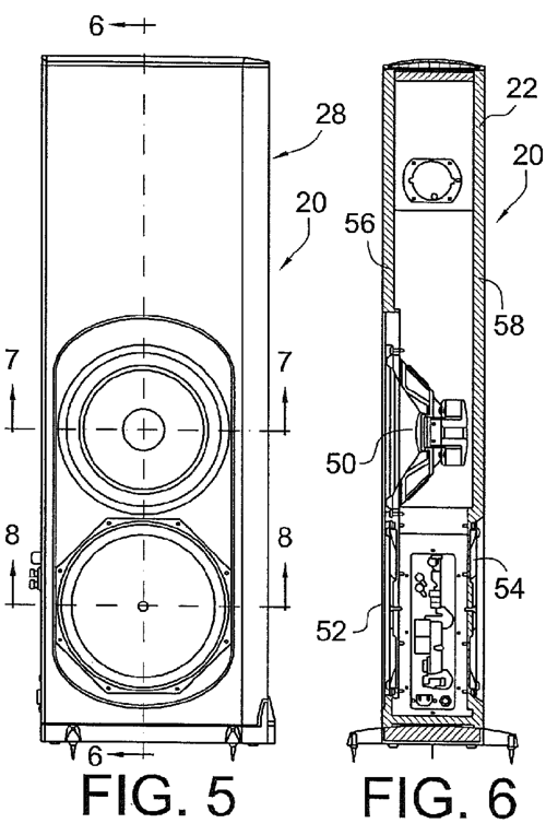


| www.tubecad.com Copyright © 1999-2021 GlassWare All Rights Reserved |