| John Broskie's Guide to Tube Circuit Analysis & Design |
02 May 2021 Post Number 535
MC Phono Preamp—Tube-Based
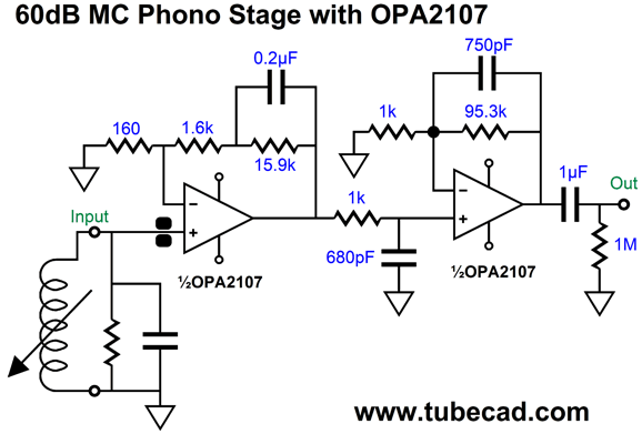
It took much tweaking to get a flat frequency response with readily available resistor and capacitor values. The input OpAmp delivers 60dB of gain at 50Hz and 40dB at 1kHz. The second OpAmp imposes the 75µs time constant (2122Hz) low-pass filter. So what do the 1k resistor and 680pF capacitor do? Then impose a low-pass filter at 234kHz, which completes the 75µs time constant when the secondary OpAmp begins to flatten due to its non-inverting configuration. If used the inverting configuration for the second OpAmp, then we would not need this additional low-pass filter.
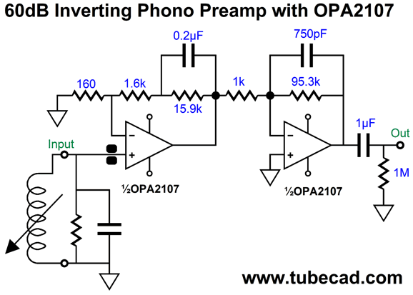
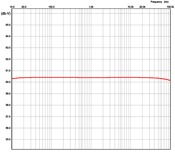
With high-gain amplifiers, inverting is safer, as we never want the output to bleed into the input, as the non-inverting amplifier will oscillate wildly. The OpAmp runs out of bandwidth at 400kHz. The resulting equalization is flat to 0.02dB from 20Hz to 20kHz in SPICE simulations.
Returning to the topic of tubes requiring much more care and consideration, for example we can forget about using a 12AX7 as the input tube, as it is far too noisy. A triode's amplification factor (mu) is the product of multiplying its transconductance against its plate resistance. Since the 12AX7's transconductance is weak, its relatively high mu is a result of its crazy high plate resistance, about 60k. For the lowest-noise amplification, the input triode should offer high transconductance and run under high current; in addition, it should offer low microphonics. The list of possible candidates is not long, with the ubiquitous 6DJ8 standing out as the only easily obtainable tube. The 6DJ8's medium mu of 33 will not go that far for creating our goal of a gain of 1:10,000 or 80dB. No, I didn't just make a typo. In order to get a final gain of 60dB after the imposition of the RIAA equalization, either active or passive equalization, we need an open-loop gain of 80dB, as the equalization loses 20dB.
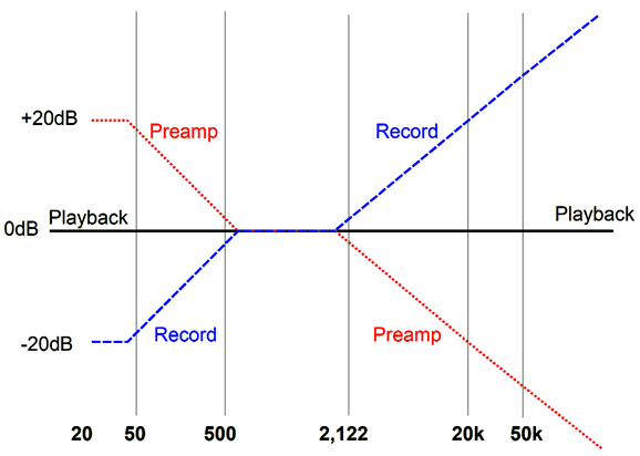
My strong preference is for passive RIAA equalization, especially with tube-based phono stages. Why? The problem with active is that negative feedback is frequency dependent, with least amount available for the bass frequencies, while the highs get too much. (With solid-state efforts, such as an OpAmp-based phono stage, the open-loop bandwidth falls off at about 50Hz, so the feedback-based RIAA equalization works far better; tubes, on the other hand, offer much less gain and wider bandwidth.)
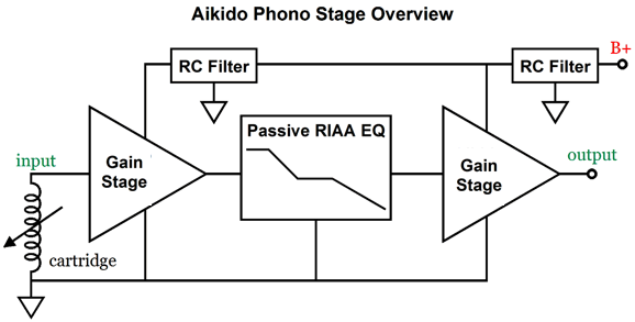
In addition, my preference is for building two gain stages and placing a passive RIAA equalization network in between the two. With two gain stages, we take the square root of 10,000 and get 100 as the needed gain for each stage. In other words, a gain of 1:100 or 40dB, as the formula for dBs is 20Log(gain). Obviously, two grounded-cathode amplifiers based on 6DJ8 tubes are not going to get us there. A cascode based on a 6DJ8, however, will.
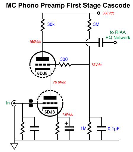
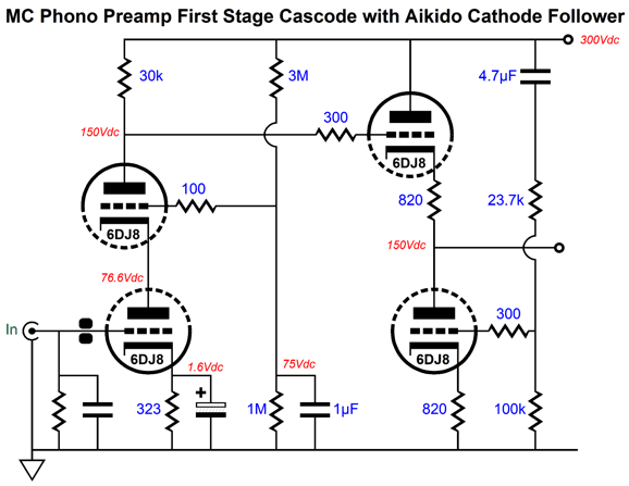
The cascode gain stage is not limited by the triode's amplification factor. In other words, we can get a gain higher than the triode's mu. In this example, the gain is 1:120 (+41.6dB). A bit of extra gain is not a problem, as we can expect signal losses along the way. True cascode problems, however, are a poor PSRR and a high output impedance. Solving its high output impedance is easy enough, as we can simply add a cathode follower.
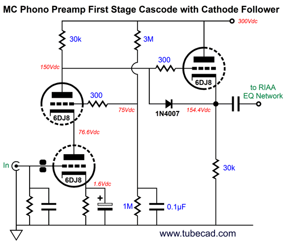
The 6DJ8-based cathode follower presents an output impedance of about 100 ohms, plenty low enough to drive the passive RIAA equalization network. The remaining problem of a poor PSRR could be fixed by using an Aikido cathode follower (ACF) in place of the plain-Jane cathode follower.
The Aikido cathode follower proactively anticipates the amount of power-supply noise that the cascode will present at its output and applies a countering inverted power-supply noise to create a power-supply-noise null at the output. In contrast, a negative feedback arrangement would first let something go wrong and then strive to fix it after the fact.
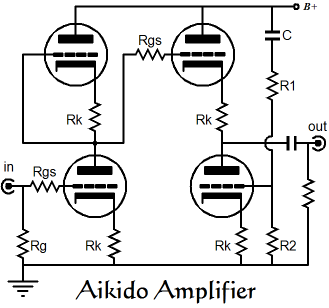
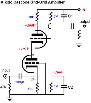
In the classic Aikido line-stage amplifier, the input stage consists of a grounded-cathode amplifier with an active load, the load being the same triode and the same cathode resistor value. The result is that the two triodes define a two-resistor voltage divider that halves the power-supply noise at its output. The cascode input stage delivers closer to 95% of the power-supply noise, which explains why so much more of the power-supply noise must be injected into the ACF's bottom triode. On the other hand, long ago, as in 22 years ago in the first issue of the Tube CAD Journal, I explained how to inject some Aikido mojo into the classic cascode.
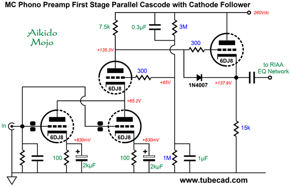
So, would this be just a giant step sideways? For most audio applications, this could justifiably be seen as a sideways move; but with high-gain phono stages, we can take advantage of the freed up triode. In the cascode with an Aikido cathode follower, four triodes were used, i.e. two 6DJ8 tubes. In contrast, a cascode and cahtode follower uses only three triodes, which allows us to put the extra triode to use in lowering the noise.
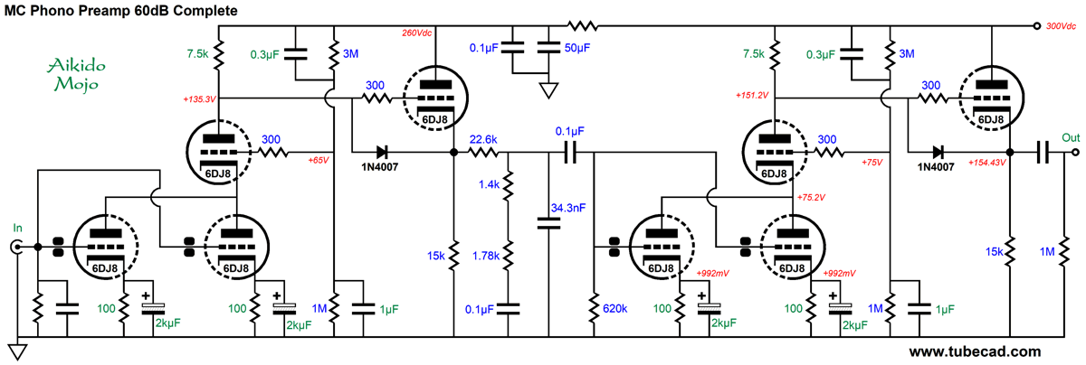
The two input triodes are in parallel, which will reduce the cascode's noise by 3dB, which is not a lot, but will take every dB we can get. The price we pay is increased current demand and heat dissipation. This circuit draws 26mA, which against a 260V power-supply voltage generates 6.76W of heat. In contrast, many tube-based phono stages do not draw anything close to 26mA for the entire phono preamp. Speaking of entire preamps, here is the entire phono circuit (for one channel). The total gain is 62dB. The price we must pay is the high tube count and the high power demands. Still, such a phono preamp would allow us to use a low-output MC cartridge without a step-up transformer or an MC pre-preamp. Since I can never cease devising circuits, here is an interesting alternative 40dB (1:100) gain stage I came up with the other day.
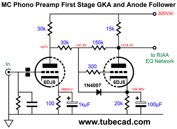
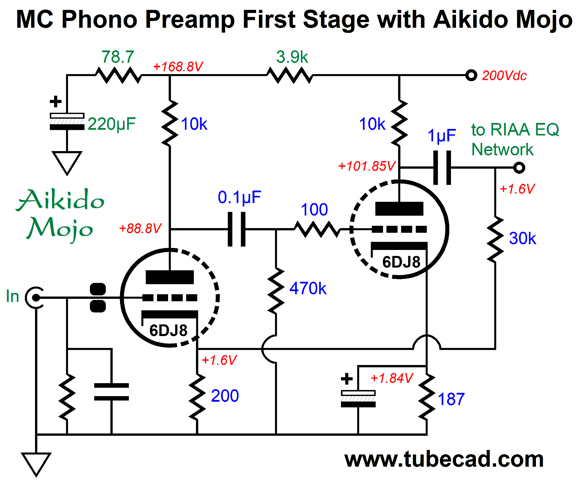
It looks like previous circuits shown here, where a grounded-cathode amplifier cascades into an anode follower (aka plate follower). The big difference is that the anode follower DC couples to the first stage. Here is the conventional arrangement from post 458:
Since we are striving for high gain and low output impedance, both cathode resistors need to be bypassed. Once I added the bypass capacitor to the anode follower's cathode resistor, I saw that I could forgo the internal coupling capacitor. The grounded-cathode amplifier provides a gain of 1:26, while the anode follower delivers a gain 1:4, making for a total of 1:104 (or about 40dB). The weak link is the PSRR, which is only -10dB. Fortunately, we can inject some Aikido mojo.
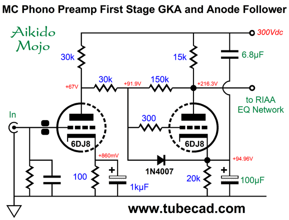
The added 6.8µF brings the PSRR down to -40dB. (In addition, the added capacitor allows us to brag about Ultra-Path mojo benefits, even if they really do not exist.)
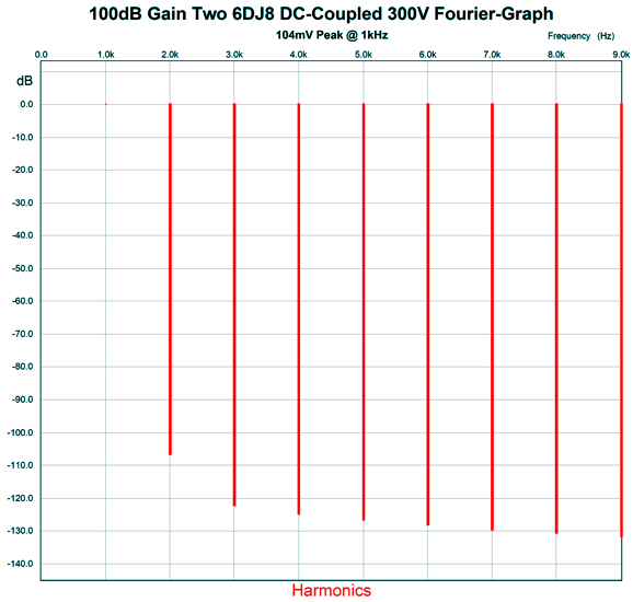
The output impedance is about 540 ohms and the distortion is low. Here is the SPICE-generated Fourier graph for 100mV of output at 1kHz.
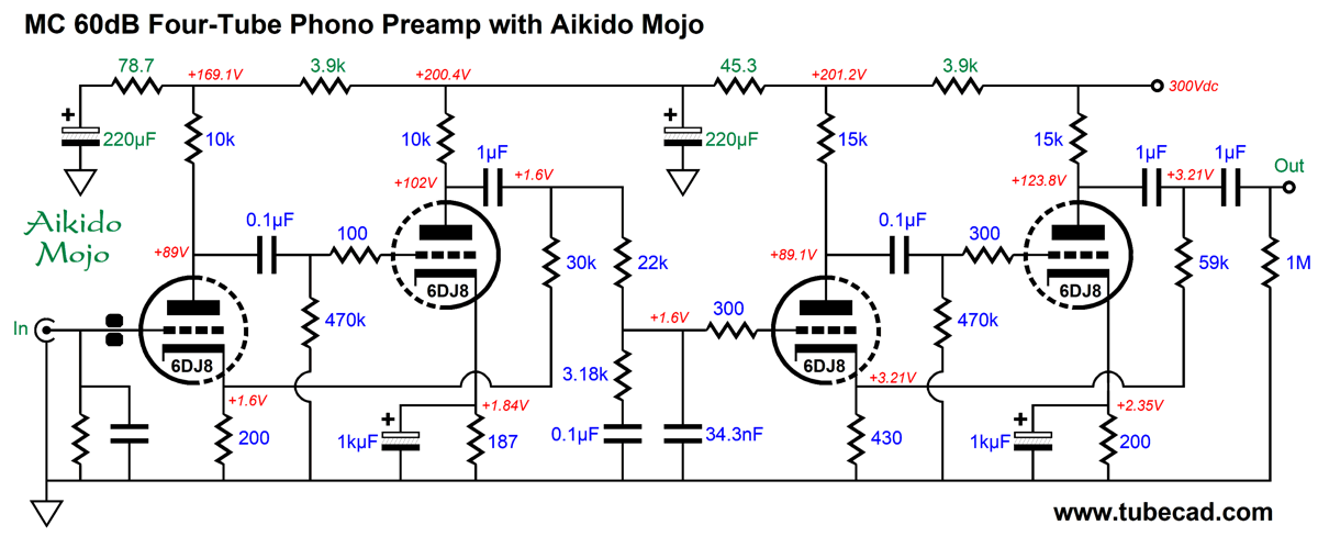
That is low. Okay, how would we assemble an entire 60dB phono stage? Much like the previous design, we would use two gain stages separated by a passive RIAA equalization network. Unlike the previous design, only four 6DJ8 tubes were needed. Moreover, only 13.5mA of power-supply current is needed per gain stage, resulting in a total draw of 54mA, which against a raw B+ voltage of 330Vdc, results in only 18W of heat dissipation. Where this design could lose is in noise. Parallel triodes are not used. The anode follower uses high-ohm resistors (30k and 150k). The true test would be to build both phono stages and listen to them. But wait. The anode follower's two feedback resistors bothered me, so I searched through previous 40dB gain stages and I found this design I made a few years ago.
Wonder how well this circuit worked out?
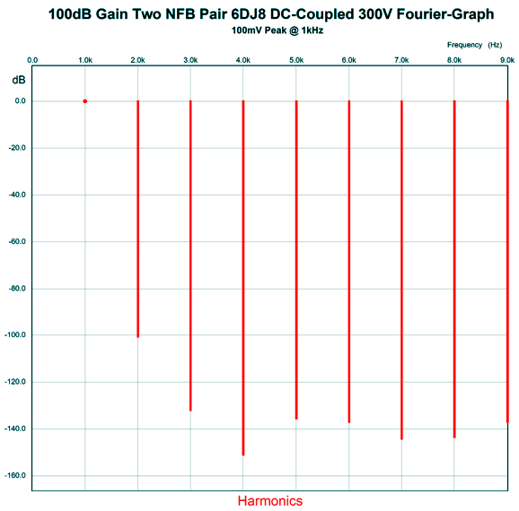
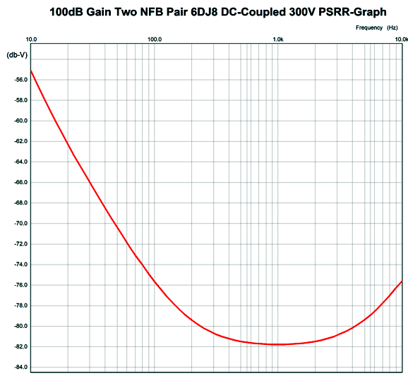
The output impedance came in at about 610 ohms. The PSRR was amazingly good:
Okay, this circuit looks quite promising, as it only uses two triodes (i.e. one 6DJ8) per gain stage, so only four tubes would be needed for the entire 60dB phono stage.
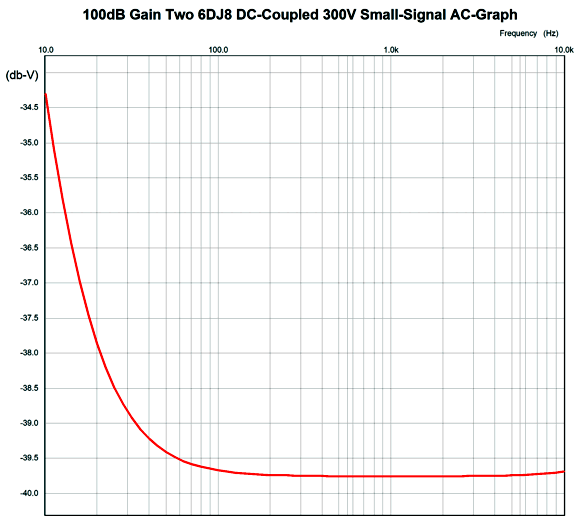
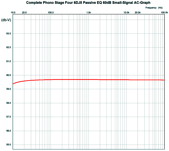
In SPICE simulations the frequency response was within 0.1dB from 20Hz to 20kHz working into a 50k volume control.
The downside to this design is that so many coupling capacitors are needed, five per channel. On the other hand, only having to use four tubes has to be a big feature.
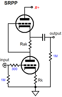
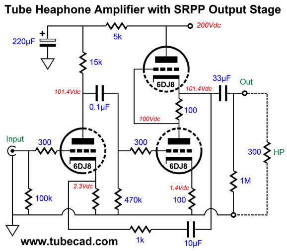
SRPP in Parallel with Grounded-cathode
By itself, a single 6DJ8 in an SRPP circuit has a hard time driving 300-ohm headphones. Adding the grounded-cathode amplifier input stage cannot increase the power output, as the SRPP output stage runs in strict class-A mode, but it can reduce the SRPP's distortion and high output impedance.
Looking at the circuit, I wondered about using two 6DJ8 tubes per channel, not 1½ tubes. Of course, we could use three tubes in a stereo headphone amplifier. But what if we did use four tubes in the same stereo amplifier, what would the added two triodes do? My first thought was that I could increase the input stage's gain by cascading the input or by cascading two grounded-cathode amplifiers. Out of nowhere, the following circuit fell out of my pencil.
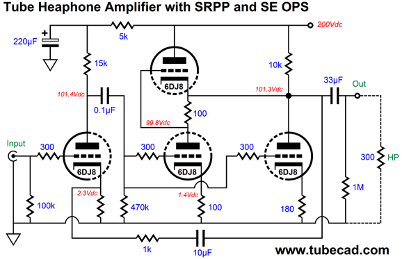
This is something completely different, as the added triode augments the SRPP output stage in driving the headphone. We have wedded push-pull to single-ended, as the added grounded-cathode amplifier is a purely single-ended effort. What do we get with this hybrid output stage? Pure push-pull output stages tend to overly suppress even-order harmonics and often display a pronounced 3rd harmonic, especially the SRPP driving a low-impedance load. Not this design.
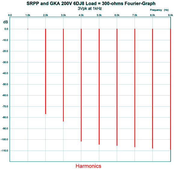
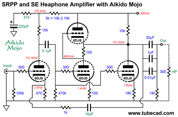
The output is 3Vpk at 1kHz into a 300-ohm load. Note the 3rd harmonic. It's suppressed, not pronounced. Indeed, the entire array of harmonic presents a lovely single-ended structure. In fact, if we use a larger output coupling capacitor, say 68µF, the distortion falls even more, which is what I did in this SPICE simulation. Okay, are we done? No, of course not. We are never done in analog electronics. The PSRR is a quite respectable -45dB. But by adding some Aikido mojo in the form of my cynosure resistor, we get something quite stellar.
The 374-ohm resistor allows a small portion of the power-supply noise to leak out of the input stage's output, which results in a power-supply-noise null at the headphone driver.
Better than 80dB at 100Hz would be good with a solid-state design, with a tube-based design it is unheard of. Mind you, such a deep null requires that the Aikido mojo part values not be changed. Here is a quote from post 505.
Often, we can make substitutions, a 0.22µF capacitor rather than the 0.1µF capacitor in the schematic. Other times, we cannot; for example, in a phono stage's RIAA equalization network or in an electronic filter. Well, the Aikido mojo belongs to this group. Okay, a good question to ask is, Could the four triodes be put to better use? I decided to create a competitor headphone amplifier that used four 6DJ8 triodes.
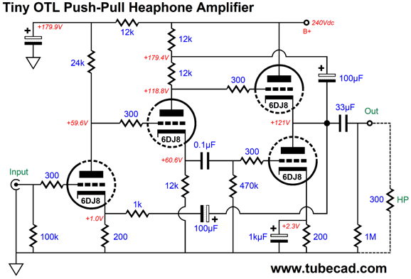
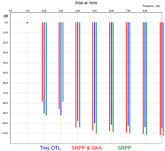
This is a proper push-pull power amplifier, albeit a tiny OTL power amplifier, that uses a split-load phase splitter to deliver the needed balanced input signals to the two output triodes. The 100µF capacitor that connects to the output and to the phase splitter is needed to ensure that both output triodes are being run as grounded-cathode amplifiers. Without this capacitor, which many leave out, the top triode would operate as a cathode follower and the bottom triode would be grossly overdriven. The negative feedback loop sets a fixed gain (about 1:5) and lowers both the distortion and output impedance. I held a shootout in SPICE with the three topologies: the three-triode SRPP-based amplifier, the four-triode SRPP-grounded-cathode amplifier, and this last tiny push-pull OTL amplifier. All three put out 3Vpk into 300 ohms at 1kHz and all three circuits held a 68µF output coupling capacitor.
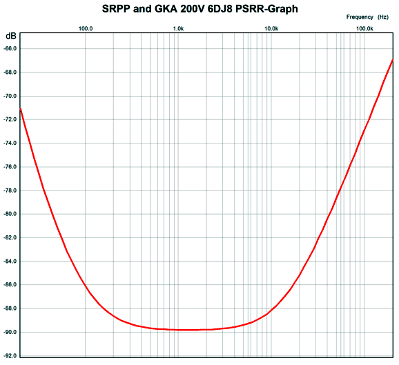
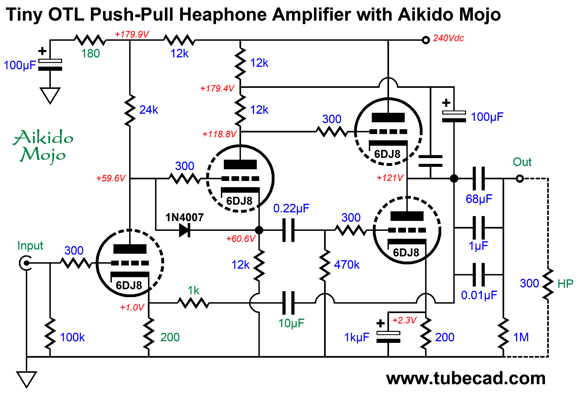
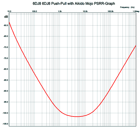
The worst performer is the three-triode SRPP-based amplifier (green), at least in terms of the 3rd harmonic. I don't see a clear winner with the remaining two designs. The four-triode SRPP-grounded-cathode amplifier (red) offers lower 4t through 9th harmonics, but higher THD. If I were a betting man, I would put my money on the four-triode SRPP-grounded-cathode amplifier, as it exhibits a stronger single-ended flavor. Believe me; if you listen to headphones for over an hour, the single-ended flavor is much easier on your ears and soul. (Of course, if your musical taste leans more in the direction of harsh and soul-crushing, a cheap solid-state amplifier is the way to go.) Before leaving the tiny OTL, we should add some Aikido mojo. Without Aikido mojo, the PSRR is respectable -46dB at 100Hz. With the mojo, better than -100dB!
Once again, the Aikido mojo part values are tightly related, so no just throwing in whatever you have in your parts bin. Look at 100Hz and 120Hz, as that is the ripple frequency.
Music Recommendation: High-Res Singers
Young American jazz singer, Anais Reno, has released a surprisingly fresh and vital jazz vocal album. All the songs were written either by twelve songs by Duke Ellington or Billy Strayhorn. She knows these songs well and somehow manages to sound a few decades older than she is. It is not enough to sing a jazz song, you must express its emotion. I hope to live long enough to hear her develop into a truly amazing singer. Irish singer-songwriter, Imelda May, can certainly sing. Alas, it was only the title track that won my ears and heart. Nonetheless, the album is well worth hearing. //JRB
*SRPP and Me In post 320, I told the story of my encounter in an elevator with one such critic at the RMAF. What can I say, other than to decry the tragedy that is so often the result of when cousins marry. I hate to say it, but I somewhat miss the hate mail. The interesting question is why did it die out? One possibility is that writing an email simply requires too much effort, now that text messaging and tweets are the primary mode of communication. The least likely explanation is that I won over my critics. Very few ever change their minds.
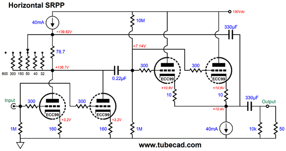
Right now, I am reading Jacob Bronowski's last book, his posthumous book, The Visionary Eye, which deals with art and science and knowledge. Bronowski was a Jew born in Poland and grew up in Germany and England and Cambridge educated. He was a mathematician, poet, philosopher, scientist—your general polymath and Renaissance man. His most famous achievement was the 13-episode BBC production of The Ascent of Man. In The Visionary Eye, he mentions that his first book, The Poet's Defense, although carefully researched and argued, changed no minds. Those who agreed with its premise continued to agree with it; those who didn't continued to disagree. Well, the SRPP and I have a long history (about four decades) and it will not end soon, as I seem to be destined to be the only one who actually comes up with new SRPP designs (sorry, but changing the name to Lampizator or using a different brand of resistors or coupling capacitors or tubes does not count). Here is an example of my efforts from post 368.
Seriously, could I come up with this SRPP variation if I didn't understand how the SRPP worked? Could those with supreme part-brand-secret knowledge have come up with it?
By the way, if you wish to ascend to ranks of supreme part-brand wizard, you need to know two undisclosed and exclusionary items: the secret hand gesture which looks much like the act of removing your credit card from your wallet and the secret wisdom that the more it costs, the better it sounds.
Did you get your money's worth with this post by me? If so, think about supporting me at Patreon.
User Guides for GlassWare Software
For those of you who still have old computers running Windows XP (32-bit) or any other Windows 32-bit OS, I have setup the download availability of my old old standards: Tube CAD, SE Amp CAD, and Audio Gadgets. The downloads are at the GlassWare-Yahoo store and the price is only $9.95 for each program. http://glass-ware.stores.yahoo.net/adsoffromgla.html So many have asked that I had to do it. WARNING: THESE THREE PROGRAMS WILL NOT RUN UNDER VISTA 64-Bit or WINDOWS 7, 8, and 10 if the OS is not 32-bit or if it is a 64-bit OS. I do plan on remaking all of these programs into 64-bit versions, but it will be a huge ordeal, as programming requires vast chunks of noise-free time, something very rare with children running about. Ideally, I would love to come out with versions that run on iPads and Android-OS tablets.
|
I know that some readers wish to avoid Patreon, so here is a PayPal button instead. Thanks. John Broskie
John Gives
Special Thanks to the Special 86 To all my patrons, all 87 of them, thank you all again. I want to especially thank
I am truly stunned and appreciative of their support. In addition I want to thank the following patrons:
All of your support makes a big difference. I would love to arrive at the point where creating my posts was my top priority of the day, not something that I have to steal time from other obligations to do. The more support I get, the higher up these posts move up in deserving attention.
If you have been reading my posts, you know that my lifetime goal is reaching post number one thousand. I have 471 more to go. My second goal was to gather 1,000 patrons. Well, that no longer seems possible to me, so I will shoot for a mighty 100 instead. Thus, I have 13 patrons to go. Help me get there.
Support the Tube CAD Journal & get an extremely powerful push-pull tube-amplifier simulator for TCJ Push-Pull Calculator
TCJ PPC Version 2 Improvements Rebuilt simulation engine *User definable
Download or CD ROM For more information, please visit our Web site : To purchase, please visit our Yahoo Store: |
|||


| www.tubecad.com Copyright © 1999-2021 GlassWare All Rights Reserved |