| John Broskie's Guide to Tube Circuit Analysis & Design |
24 September 2020 Post Number 514
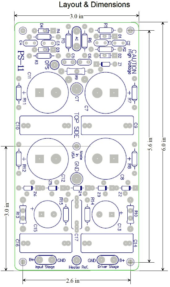
PS-11 High-Voltage Power Supply
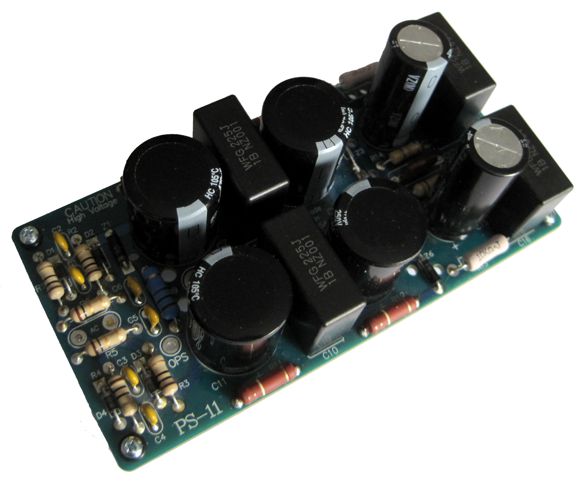
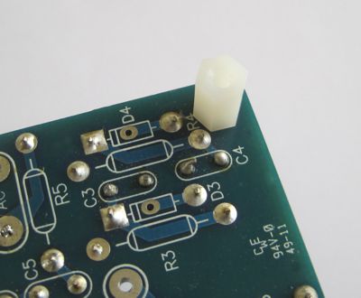
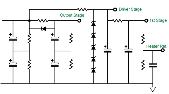
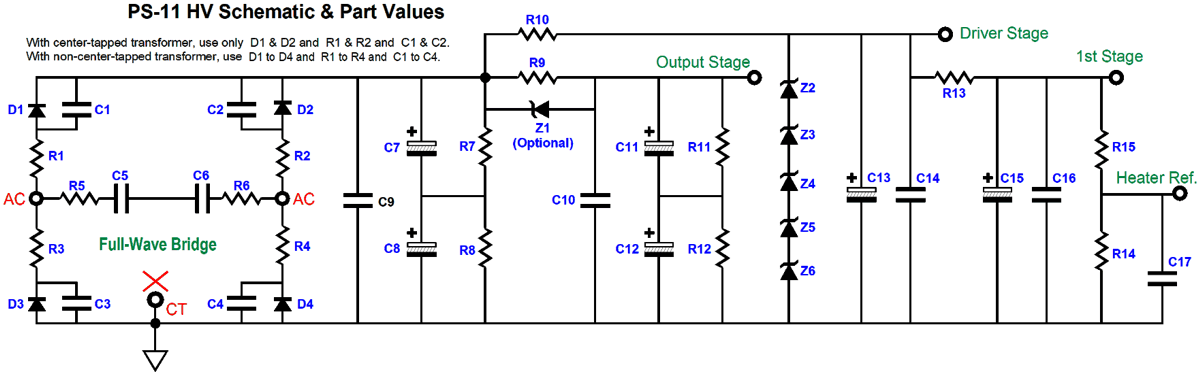
Everything was great, until a metal 1/4 inch standoff was attached to the PCB. Well, the workaround is not to use metal standoffs, replacing them with nylon standoffs, which I fortunately have. The PS-11 makes building a tube power amplifier much easier, as it provides three output voltages taps: one for the output tubes, one for the driver stage, and one for the input stage. The output stage consists of two 470F/250V capacitors (C7 & C8) in series, making for a total of 235µF of capacitance and a 500V rating, which then travels through a an RC filter (R9, C11, C12) that holds the same two 470µF capacitors in series; both sides are bypassed by 2.2µF/630V capacitors polypropylene capacitors. Each 470F/250V capacitor is shunted by a 110k/3W bleeder resistor that also ensures equal voltage division between capacitors. Here is the simplified and truncated schematic of the circuit after the rectifiers.
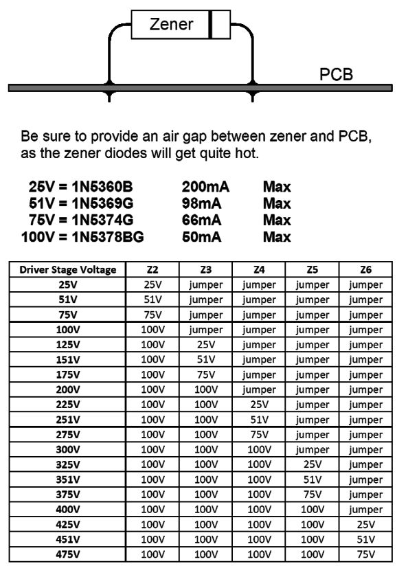
The RC resistor can be shunted by an optional 12V zener, which would function much like a swinging choke, as at idle the RC filter scrubs away ripple, but at full output the zener engages; thus, the output tubes do not see their B+ voltage collapse, as the zener's engaging stops the voltage from dropping any further across the RC resistor. On the other hand, we could leave resistor R9 off the PCB and attaches the leads from an external choke instead. I would leave the zener in place. The driver stage offers the option shunt regulation of the voltage with a string of zeners. The input-stage output cascades from the driver stage, so it can benefits from the regulation. These last two voltage outputs also use RC filtering that hold 47µF/500V capacitors, bypassed by 2.2µF/630V capacitors polypropylene capacitors. By using four zener break voltages, we can select the shunt regulated driver-stage voltage in 25-volt increments.
The zener current limits should never be approached, save at turn-on, when no tubes are conducting yet. A quick rule of thumb might be that the zener should draw about half the current as the driver stage. No heater power supply is provided, as the 6.3Vac winding is used to power the heaters in most tube-based power amplifiers. (Most existing tube power amplifiers cannot support DC voltages for all the heaters, as their power transformer heater winding voltage is too low and its current rating too weak to suffer the rectification losses.) The PS-11 does hold, however, a two-resistor voltage divider and capacitor shunted circuit to reference DC voltage to the AC heater winding, which helps prevent hum. Here is the complete schematic for the PS-11.
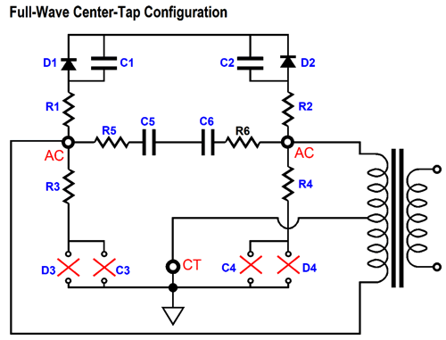
The schematic shows the full-wave bridge setup, where a secondary without a center-tap is used. To use a center-tapped secondary, as most tube power amplifier power supplies do, we leave the following parts off the PCB.
Resistors R5 & R6 and capacitors C5 & C6 serve as high-frequency snubber circuit that converts HF hash and RFI into heat.
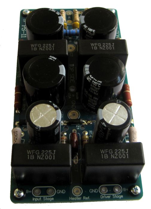
The PCB is quite compact, in spite of the big capacitance it holds.
The PS-11 high-voltage power supply kit is available, which includes all the parts and nylon standoffs and optional zeners, at the GlassWare-Yahoo store.
Alternative Transformer-Coupled Output Stages
Let's start by creating a list of specifications and operating points needed for 36 Watts of output into an 8-ohm load. Starting with the loudspeaker, for an 8-ohm load to experience 36W of dissipation, it needs to see a peak current flow of 3A and peak voltage swing of 24Vpk. Note that 24V against 3A equals 72W of peak power, but only 36W of average (or what was once called RMS power). The math is easy: Vpk = √(2 ∙Watts ∙Rload) and Ipk = √(2 ∙W/Rload).
Moving on to the output transformer, we assume an output transformer with a primary impedance of 3200 ohms. From this first assumption, many specifications ensue. We find the impedance ratio by dividing 3200 ohms by 8 ohms, and we get 400:1; if we attached a 4-ohm loudspeaker, the reflected impedance on the primary side would be 1600 ohms; a 16-ohm loudspeaker, 6400 ohms. Next, we take the square-root of the impedance ratio (400:1) and we get the voltage ratio and the inverse of current ratio; in this example, the voltage ratio is 20:1, the current ratio, 1:20. Remember that a transformer transfers the same power on the primary to the secondary. Thus, if the secondary voltage falls, the secondary current must rise to ensure the same power transfer. In addition, the winding ratio is equal to the voltage ratio. From the primary side, we find the required peak voltage swing by either multiplying 24Vpk by the winding ratio (20) or by taking the square of 2 x 3200ohms x 36W, as Vpk = √(W2Rload); either way gives us a peak voltage swing of 480 volts. To find the peak current flow we can either divide 480V by 3200 ohms or by taking the square of ((2 x 36W) / 3200 ohms), as Ipk = √(2W/Rload); both yield 150mA peak. Here is the complete list:
This was the easy stuff. The hard stuff to understand is how an output transformer works in a typical push-pull tube-based power amplifier. Do you think that you already know how an output transformer works in a push-pull amplifier? Okay, given the above specifications and voltage and current operating points, what is the load impedance seen by either output tube? If you guessed 3200 ohms, you are wrong; if you guessed 1600 ohms, you might be right—but only if the output stage is running in strict class-A. Most likely, the correct answer is 800 ohms, as almost all push-pull tube-based power amplifiers run in class-AB. Since this will not make sense to most readers, let's start with a totem-pole arrangement that is loaded by the output transformer with a primary impedance of 3200 ohms.
To get 35W of output the primary must see a peak voltage swing 480V. This means the bipolar power supply must hold at least +/-480Vdc. In fact, reality will demand far more power-supply voltage. How much more? Let's assume that the triode's plate resistance is 400 ohms. Well, with a grid-to-cathode voltage of 0V, the triode will drop 60 volts with 150mA of current draw. Thus, we must increase the total power-supply voltage by 120 volts, bringing the bipolar power supply to +/-540Vdc, a total of 1080 volts. Now pause and consider how most push-pull, transformer-coupled, tube-based power amplifiers that put out 36W do not run 1080Vdc power supplies, but something closer to 450Vdc. Let's assume an idle current flow of 50mA per tube. As soon as a negative grid-voltage swing is large enough to cutoff an output tube, its brother is left doing all the work. The transition points occur at 0mA and 100mA in this example. With one output tube completely shut off, this dormant tube is effectively out of the circuit, leaving the other output tube conducting like mad, as it sees the primary winding ratio fall to half that of the plate-to-plate ratio when both tube were conducting. Since we square the winding ratio to find the impedance ratio, halving a winding ratio results in the primary impedance falling to just 1/4th the plate-to-plate value. Thus, the single active output tube sees a load impedance of 800 ohms. We divide the peak voltage swing of 240V by 800 ohms and get a peak current swing of 300mA.
Note that, compared to our original calculations, we have halved the peak voltage swing, but doubled the peak current swing. Let's run the math: 300mA against 240V equals a peak power of 72W and average power of 36W. No laws of physics were broken. We didn't get something for free, as we paid the price in the doubled current flow to offset the halved peak voltage swing. Okay, let's increase the idle current flow to 150mA per output triode, so the combined current flow is 300mA. In addition, let's decrease the B+ voltage to theoretical minimum with the 3200-ohm primary impedance and the triode plate resistance of 400 ohms, i.e. 360Vdc. This B+ voltage against the combined current flow equals 108W. To find the output stage efficiency we divide the output power by the idle dissipation; in this example, we divide 36W by 108W and get 33.3%, which falls short of the textbook theoretical efficiency of 50%. To get to 50% the triode would have to exhibit a plate resistance of zero. In other words, not possible. (The way some tube amplifier manufacturers do the math is to note that the power amplifier draws 80W from the wall socket, a large amount relative to its power output due to the power also consumed by the rectification losses, transformer losses, input and driver stages power consumption, the power dissipated by the negative feedback resistor, the heater dissipation, and the power indicator light. Then they divide 36W by 100W and get an efficiency of 36%, and conclude that their amplifier must be a class-A type, as any amplifier that meets or falls short of 50% is ipso facto a class-A amplifier. Imagine you own a car that gets dismal gas mileage. Can we conclude that your car must host a 427 cubic-inch engine that roars with power? It might. It also might sport a poorly maintained two-liter engine. Worse still, some do not even use a calculator, as they believe that all cathode-biased output stages are by that very fact class-A output stages. I wish I were making this up, but alas, I am not.) Okay, what would qualify as true class-A operation? Each output tube would have to idle at 150mA. As one tube cuts off, the other conducts at 300mA. The remaining turned-on tube has experienced a 100% increase in current flow and its plate voltage has fallen by 240V. Thus, the load impedance seen by this still conducting tube is equal to 240V/150mA or 1600 ohms, half the primary plate-to-plate impedance. Yet, all of 300mA flows through the half of the primary that still conducts; thus, we end up with 36W of output power at the secondary. The output stage efficiency is 33.3%, as 36W/108W equals 0.333. Well, that was the textbook explanation. What many a tube-based amplifier maker will tell you is that the textbooks are wrong, as they run 130mA per output tube and get 36W of class-A output power, as no output tube ever completely cuts off. What's going on? Tubes are not perfectly linear; they are especially not linear at the bottom of their plate curves, as it is harder to turn off a tube's conduction than it is to turn it on. So, are these amplifier maker's right? Not really. It is not enough to remain conducting, as the conduction must be useful conduction, which means complementary inverse conduction. Here is an analogy: you and a friend must pull up a heavy bucket of water ten feet from a well. You attach a thick woven steel cable to the bucket; your friend, a bungee cord. You pull up ten feet of steel cable; he pulls ten feet of spongy cord out of the well. Did he work as hard as you did? Returning to amplifiers, if we actually measure the amplifier with gooey output tubes and 150mA idle current per output tube, we will find that that at 36W of output, one output tube is conducting 320mA, while its partner still conducts 20mA. What we have is a sloppy class-A amplifier, as the tube's leaky turn off simply becomes a burden for the more active tube. Sloppy is seldom efficient. What if none of the output tubes ever completely turn off and the idle current is 50mA per tube, is this still a sloppy class-A amplifier? No. It is a sloppy class-AB amplifier. Class-A is only valued because of its lower distortion and constant output impedance, the result of it being a constant-transconductance output stage. If the output impedance and distortion rises as the power output increases, we derived no sonic benefits from the alleged class-A operation, other than bragging rights with our fellow audiophiles.
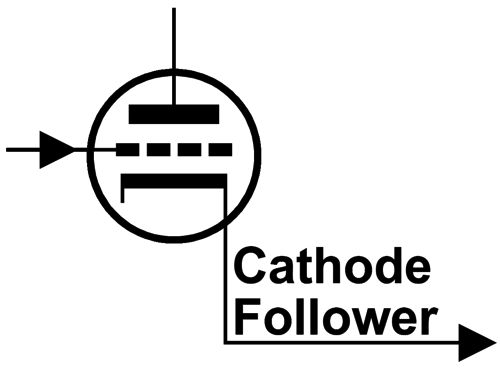
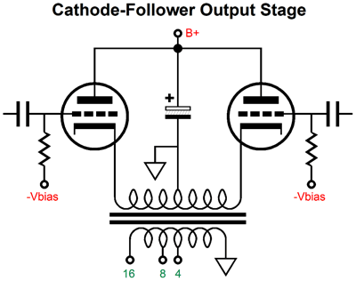
Push-pull Cathode-Follower Output Stage
If we try to cheat the system by bootstrapping the driver stage by attaching it to the output tube cathodes, however, we are punished by losing those desired attributes. Just because an output stage looks like a cathode follower does not guarantee that it functions as cathode follower. I have covered this topic before, in post 48, 49, 50, 53, 230, 320 , I believe that the last time I examined a push-pull cathode follower output stage was last May, in post 504, where I showed a schematic from the late 1940s.
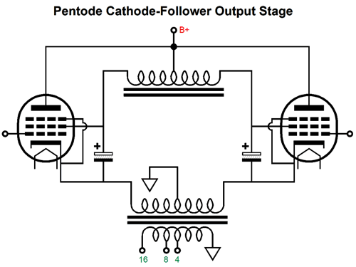
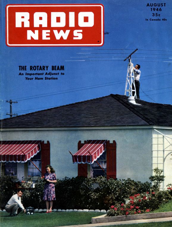
My memory complained that I had seen an even earlier example. Amazingly enough, I found it in the 1946 April issue of Radio News magazine. I scanned and OCRed the article for all of you. It's at the very bottom of this webpage. The article is well worth reading. The one issue I take with the author's conclusions is with his contention that pentode operation of the output tubes is not feasible with the cathode follower topology. He misses an easy workaround.
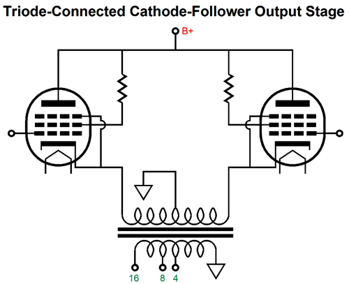
The addition of the center-tap choke allows us to feed the pentode's grid-2 DC voltage that is referenced to their cathodes. As the cathodes swing up and down in voltage, so, too, the grid-2s, as the capacitors maintain their charge and the center-tap choke allows the fee AC swings. As an added bonus the grid-2 current flows through the cathode and the primary. Instead, the author triode-connects the pentode output tubes.
For the longest time, I have been wanting to build a power amplifier with a cathode follower output stage—but which also doubled as an electrostatic headphone amplifier. The idea is simple. I build a stereo electrostatic headphone amplifier based on my ES-HPA-1 or ES-HPA-2 PCBs, which will hold a rotary switch that will send the output signal either to electrostatic headphones or to the grids of a cathode-follower power amplifier. (In addition, the switch would shut on and off the output tube heaters as needed.) I was thinking of a relatively low power amplifier to drive computer speakers, say one that held two EL84 output tubes per channel.
Well, since writing about two-amplifier cascades, where a power amplifier consists of two amplifiers in series, each with its own negative feedback loop, I see that we can treat the cathode-follower output stage as effectively constituting a good second amplifier, as the cathode follower's 100% of degenerative negative feedback counts as a negative feedback loop, the shortest one possible.
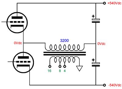
As I pondered such a design, I wondered about going bolder by building a much bigger cathode follower power amplifier, say one that put out 50W to 100W. As I ran the math, I quickly discovered that such a beast would require a huge balanced input signal that swung something like +/-480Vpk. In other words, the driver stage would require power tubes and scary high-voltages. The more I thought about it, the less I thought it desirable or even possible—until the transformer-coupled circlotron came to mind, as this output stage would deliver the same high power output but halve the required balanced input signal to +/-240Vpk, which is well within the range of my existing electrostatic headphone amplifiers.
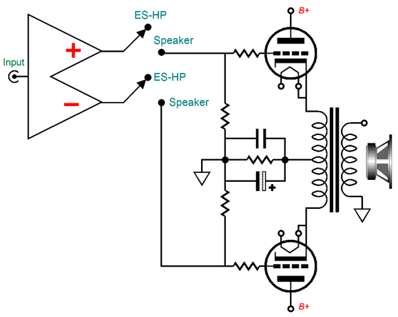
Transformer-Coupled Circlotrons
As my fingers danced across the calculator, my hopes quickly ran into an unforeseen problem: the output transformer. If you didn't just skip down to here and started to read, you saw in the previous section how—in the conventional transformer-coupled power amplifier—the output transformer effectively presents one quarter of the plate-to-plate impedance. For example, a 3200-ohm primary impedance effectively becomes an 800-ohm load. This same 3200-ohm primary in a circlotron output stage remains a 3200-ohm load, as the two floating power supplies are effectively dead shorts in AC terms. So, is that a problem? Run the math and you will see that it is. For example, say we want 36W of output with our 3200-ohm output transformer. The entire primary must then see 480Vpk voltage swings and 150mA peak current swings. Assuming a plate resistance of 800 ohms for the output triode (a 300B's rp is about 800 ohms), the peak voltage drop would 120V. We add 120V to 480V and we get 600V as the minimum floating power supply voltage. Not good. If the primary impedance is 5k to 10k, it's even worse.
Sadly, 600V is an awkward B+ voltage, as the power-supply capacitors will prove rare and expensive. In addition, if we try running class-A, the required idle current of 75mA per output tube will result in 45W of dissipation; moreover, the idle plate 600V voltage exceeds the limits of most audio output tubes. In other words, it looks like we would need to use radio transmitting triodes, such as the 845. Ideally, we would want a 36W output transformer with a primary impedance of 800 ohms, as we could then use normal output tubes, such as the EL34 and KT88, and far lower floating power-supply voltages. To get 36W, the 800-ohm primary must see 240V peak voltage swings and 300mA peak current swings. The winding ratio would be 10:1; the impedance ratio, 100:1; the current ratio, 1:10; and the voltage ratio, 10:1. Usually, the lower the winding ratio, the better the transformer performance. All of which is great, but they don't make such an output transformer. True, we could have custom transformer wound, but that would prove a hassle and expensive, while offering no established performance. Well, there's a workaround, if you plan on driving 4-ohm loudspeakers and if the output transformer holds a 16-ohm output tap. The output transformer expects to see a 16-ohm load attached to its 16-ohm tap, which allows it to reflect a 3200 ohm load at its primary. What if we attach a 4-ohm load instead? The primary impedance falls to 800 ohms.
The 800-ohm primary will now see 240V peak voltage swings and 300mA peak current swings and the 4-ohm loudspeaker will dissipate 36W. Here is the math: In order for the 16-ohm secondary tap to deliver the same output wattage into a 16-ohm load as it does with an 8-ohm load attached to the 8-ohm tap, the 16-ohm tap must deliver 1.414 times more voltage swing that the 8-ohm tap. Thus, the 16-ohm tap must present a lower winding ratio than the 8-ohm tap. How much less? The inverse of 1.414, which is 0.707. We multiply 0.707 against the 8-ohm tap's 20;1 ratio and we get 14.14:1 as the 16-ohm tap's winding ratio. Next, we divide the primary's 240V peak voltage swing by 14.14 and get 16.97V peak voltage swing from the 16-ohm tap, which equals 36W into a 4-ohm load. Isn't math great? Okay, there's another workaround to the problem of excessive primary impedance, but only if the output transformer offers a split primary, such as the output transformer used in the Heathkit WM-6 and in some Audio research amplifiers.
By placing both primaries in parallel, we halve the winding ratio, which results in quartering the impedance ratio, so the parallel primaries present an impedance only one fourth that of the plate-to-plate impedance.
Well, another possible workaround is to use two high-impedance output transformers.
If we use two output transformers per channel, we can get away with using just one power supply. In addition, we can use existing output transformers with high plate-to-plate impedances. By the way, two transformers are not twice as expensive as one transformer, as we could use two 50W output transformers instead of one 100W transformer and still get 100W of output. Each output transformer would provide half of the output power. An analogy to this setup would be the standard circlotron loaded by two 16-ohm loads.
As far as the tubes are concerned, the load impedance is 8 ohms, as the two 16-ohm resistors are effectively in parallel with each other. By the way, both resistors see the same voltage swings and current flows and output impedance.
In this circuit, the output tubes are configured as true pentodes, as the cathode-to-screen voltage remains constant, in spite of the cathodes swinging up in down in voltage. Of course, we could wire the pentodes up as triodes, as shown below.
Why do I include a grid-2 resistor, as we could just attach grid-2 to the plate? Have you ever seen a power output arc? I have. It's a scary sight. Fortunately, no amplifier I have owned has experienced an arc, but then I don't play as loudly as most audiophiles, in spite of what my wife might say. In addition, I always use plate-stopper and grid-2 resistors. These resistors not only act as fuses, but also as current limiters. I would love to see a well-designed experiment that pitted a set of output tubes against each other, with one using grid-2 and plate-stopper resistors, the other nakedly attaching to the output transformer. We would then blasts the grids with a huge balanced signal. My bet is on the resistor-protected output tube never arcing. It may want to arc, but as the huge torrent of current flows through the resistors, the voltage drops across the resistors grows so large that the arc is no longer feasible. If the two output transformers offer ultra-linear taps, we could use them.
Yes, it is confusing, which is way I left it for the end. It might help to imagine the electrolytic capacitors replaced with jumper wires, as they would better reveal the AC relationships. What if the two output transformers do not offer ultra-linear taps? We can force an ultra-linear ratio of 50% with the following design.
The pentode's grid-2 will move in anti-phase to its grid. How is that possible, as bottom grid-2s see a fixed DC voltage. It's all relative. Relative to the cathode is what is important. Imagine that the left tube's cathode swings up by 100V, while its plate voltage swings down by 100V. Relative to the cathode, the plate voltage fell by 200V, while its grid-2 fell by 100V, 50% in other words. At the same time, the right tube's cathode-to-plate voltage swings up by 200V, while its grid-2 voltage swings by only 100V, 50% once again. Why did I use two capacitor and not one? Whatever ripple rides on the B+ voltage will be halved at the cathodes and plates, as the two primaries form a 50% AC voltage divider. Thus, we need to deliver 50% of the B+ voltage ripple to the two grid-2s. Moreover, the balanced input signal should carry the same 50% of the power-supply noise, so that the output tubes would effectively be blind to the ripple. Here is one possible frontend that offers a gain of 137, which is probably a tad short of what we need to bring about full output with 1Vpk of input signal. Of course, if a balanced input signal would double the gain.
I labeled the B+ voltage as being 400Vdc, but it should be whatever the B+ voltage the two-transformer circlotron stage uses. Adding an extra RC filter would worsen the PSRR, not improve it. Well, that was some trek, but we have finally arrived at the sneaky part, which is always the part I like best. Remember that the problem we faced was that typical output primary impedances were just too high for use in a circlotron. Well, the trick we pull off is to effectively reduce the primary impedances by half and then place the two in parallel, yielding a load impedance equal to one quarter of its nominal plate-to-plate impedance. Not by magic, but by math, which is vastly more powerful.
Note the phasing of the output transformers. Note that the two secondaries effectively work in anti-phase to each other. Note that the 8-ohm loudspeaker attaches to both 8-ohm output taps, which effectively loads each secondary by 4-ohm, not 8-ohms. The winding ratio remains unaltered, so the 4-ohm load is reflected to the primary as 1600 ohms (we are using the 3.2k output transformer of the previous examples). Due to the AC short presented by the large-valued capacitors, the two primaries are effectively in parallel in AC terms with both output tubes, so each primary sees half the peak current flow that the full-on output tube experiences. For example, at full output, the left output tube will draw 300mA, which will divide evenly between each primary, so each primary will undergo a peak voltage swing of 240V. At the same time the 20:1 winding ratio will deliver 12Vpk at each secondary, which combine to 24Vpk, as that is what the loudspeaker sees across its terminals. Let's do the math: 24Vpk across 8-ohms results in 36W od dissipation, as 24²/(2x8) = 36. Well, we have the desired output voltage, but do we have the needed output current? Yes. The transformer's current ratio is the inverse of its winding ratio, or 1:20 in this example. The tube pulled 300mA and each primary got half, so 150mA times 20 equals 3A; 3A peak AC into 8 ohms equals 36W, as 3² x 8/2 equals 36. We passed the math test. Note that while the two primaries were effectively in parallel, the two secondaries are in series with each other. If we own 4-ohm loudspeakers, we attach the speaker across the two 4-ohm output taps; 16-ohm loudspeaker, the two 16-ohm output taps. If the output transformers are rated for 20W, their combined output power is 40W.
Okay, time to pull back and take the big view. This two-transformer circlotron offers close to the cathode follower output stage's low distortion and low output impedance, but only needs half the input signal. This is a huge advantage, as we can use the B+ voltage through the amplifier. In addition, we know if an existing tube-based push-pull power amplifier works, we could double up on it to make a two-transformer circlotron with twice the output power.
For example, a Dynaco ST-70 holds two 35 watt amplifiers. If we converted the stereo amplifier into a monoblock amplifier, we would get 70W of output. We would even leave in place the two sets of output terminals and power supply, although augmented by the cross-coupling capacitors. What we would add is an input stage and driver stage capable of swinging the needed balanced signal for the mono circlotron output stage. Ideally, the input stage would offer an exemplary PSRR, while the driver stage's PSRR would come in at -6dB, so it could attach directly to the B+ voltage. The big difference presented by this double-barrel version is that the 8-ohm loudspeaker would attach to the two 16-ohm taps, not the 8-ohm taps. Why? The mono amplifier would put out 70W, not 35W, so 1.414 more peak output voltage swing is needed, which the 16-ohm taps provide, as each puts out about 17Vpk. Since the 8-ohm speaker sees +17Vpk and -17Vpk, the total comes to 34Vpk, which results in 72W of output power. I can imagine some wanting to build a 200W amplifier, but can only source 100W output transformers. Well, they could get their 200W with two 100W transformers. I imagine that six KT88 output tubes would do the job.
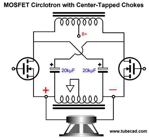
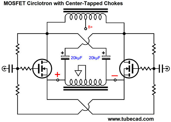
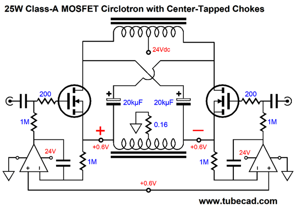
Two-Choke MOSFET Circlotron
The loudspeaker directly couples to the MOSFET sources, with no intervening source resistors, as the bottom CT choke's own DCR serves as a source resistor. How do we bias such an output stage? We could get sneaky and use a garter-belt approach that also works to self-balance away a DC offset.
The assumption is that matched MOSFETs would be used. We could add a potentiometer to one side to allow fine adjustments. Another possibility is to add two DC servos and run the MOSFET in class-A, i.e. high current mode.
The 0.16-ohm shared resistor and the bottom chokes DCR are used to measure the idle current flow through the MOSFETs. The small 0.6V DC offset is not a problem, as the speaker is blind to it, as the speaker is a truly differential device that ignores common-mode voltage. Each MOSFET draws 1.5A at idle, which against the 24Vdc B+ voltage makes for 36W of dissipation. In other words, big heatsinks are required. Since this is a unity-gain output stage, a balanced input signal of +/-21Vpk will be need, something that a simple tube frontend could easily do. If a 48Vdc power supply were used, we could get 100W into 8-ohm loads, but we would have to forget about running class-A, unless we are willing to pay the price in many more MOSFETs and a much bigger heatsink. Remember, the theoretical maximum efficiency for Class-A is 50%; thus, if the OPS is putting out 100W, at idle it must dissipate at least 200W.
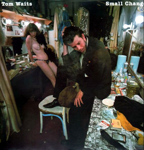
Music Recommendation: Small Change The album's musical genre is hard to pigeonhole. Waits was usually found in the rock section of record stores, but this album is far closer to jazz, with Shelly Manne on drums, Jim Hughart on upright bass, Lew Tabackin on tenor saxophone, and Waits on piano. It's been described as "beatnik-glory-meets-Hollywood-noir period." For that description alone, it is well worth hearing.
//JRB
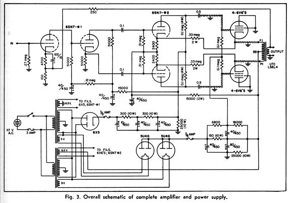
CATHODE FOLLOWER for POWER AMPLIFIER
ACCELERATED electronic development during the war has brought to light many new and useful tube applications. Among these is the cathode follower. Reams of calculations, and many articles, show the usefulness of this choice item. Now we have a practical application that is well worth consideration by anyone who enjoys the high fidelity reproduction of sound, particularly those whose funds are limited. What advantages accrue to those who use cathode follower connection of the output tubes, instead of the conventional method? What is desirable in an output amplifier when viewed from a fidelity standpoint? There are two points which should be considered in order to meet the desired characteristics, i.e., flat frequency response, and reasonable economy. When the load is placed in the plate circuit of a tube, the impedance of this load, which is usually an output transformer and speaker, must be so proportioned as to get the maximum power from the tube, and still maintain a low level of distortion. This load impedance is usually many times the impedance of the tube for the above conditions in the case of a triode. For instance, the 2A3 has a plate resistance of 800 ohms, but the output transformer is usually designed to reflect 2500 ohms to its plate. In the case of a pentode, such as the 6L6, the plate resistance is in the order of 35,000 ohms. A transformer which would reflect several times this impedance from an 8 ohm voice coil would be impractical, because of the enormous turns ratio involved. The manufacture of an audio transformer becomes increasingly difficult in proportion to the turns ratio, so a lower value is chosen, usually from 3200 to 10,000 ohms, depending upon how the tube is used. A more compelling reason exists for choosing a lower output impedance for pentodes, namely, the necessity of keeping distortion down to an acceptable value. This then, leads us to believe that the lower the output impedance of a tube used as an output amplifier, the better the result obtained with a given output transformer. The speaker must also be considered. Speakers are usually rated as having a certain impedance, at so many cycles, say 8 ohms at 400 cycles-per-second. However, this impedance value is different for different frequencies. It might be very low at low frequencies, and very high at high frequencies, and its impedance will vary radically at such points where the cone or spider structure, or baffle resonates. These changes of impedance are of course reflected back to the plate of the tube through the output transformer. This means, then, that the tube does not see a constant impedance, but a variable one. If a circuit is designed that gives a certain distortion value at 400 cycles-per-second, because an output transformer with the proper turns ratio to reflect an impedance of say 2000 ohms has been provided, then 50 cycles-per-second is applied, only an impedance of 500 ohms is reflected, because of the change in speaker impedance, then the distortion value has changed. Now, electrically the output impedance of the tube may be considered to be in parallel with the reflected impedance of the speaker output transformer combination, which simplifies to two resistances in parallel. It is fairly obvious that if one resistor is much smaller than the other, say ten times, a change in the larger, of fifty percent, will have a small effect on the resistance of the parallel combination. It is shown, therefore, that the lower the output impedance of the tube, the less control the speaker will have on the distortion of the circuit. Simply stated, the tube acts as a damping resistance on the speaker and output transformer. The lower the resistance of the tube in comparison with the speaker-transformer combination, the less pronounced will all the resonant peaks be, and the lower the attendant distortion. The speaker and transformer will exhibit characteristics more like a pure resistance and less like an inductance. This illustrates why pentodes are seldom used any more without some mechanism to compensate for their very high impedance which has a very small damping effect on the speaker. The lowest Plate resistance of any of the well-known tubes is the 2A3 or 6A3 which is in the order of 800 ohms. If that resistance could be lowered or its effective impedance reduced by a large factor an improvement in reproduction would be achieved. This can be done by hooking the tube up as a cathode follower. The effective output impedance of a 6A3 hooked as a cathode follower is in the order of 150 ohms. Furthermore, as a cathode follower has 100% degeneration, all the benefits that this provides are received, such as insensitivity to plate voltage changes, small necessary filtering in the power supply, non-critical bias requirements and insensitivity to individual tube characteristics. Furthermore, the output transformer may be much less expensive and still yield superb results. The author has actually used a small power transformer for an output, by hooking the push-pull cathode follower cathodes to the center tapped high voltage winding and connecting the speaker to the 2.5 volt filament winding! The response was reasonably flat from 50 to 8000 c.p.s. Of course a power transformer will not yield as good results as a high quality output transformer but it will still produce results quite adequate for AM radio reproduction and ordinary phonograph records. So much for the advantages. Now there is a catch to the cathode follower, but it is not an insurmountable one. The cathode follower does not have any gain, as a matter of fact, it has a loss of a few per-cent. Therefore, driving voltage equal to 110% of the required output voltage must be provided. If 150 volts swing are required across the output transformer to yield the wanted power output, then the cathode follower grid must be driven with 165 volts. The term "drive" is used figuratively, as really there is no power required, merely voltage. This simplifies the problem considerably, because a class "A" input transformer may be used, preferably with a step up ratio of 1 to 2 or more. As the driver can only swing so many volts, usually in -the, order of 65 to 90 volts, it is necessary to step this up to the assumed 150 , volts. This problem is further simplified because a cathode follower also degenerates its input capacity to practically zero. This allows the use of an input transformer of the less expensive type which usually has a higher inherent shunt capacity across the secondary. This capacity limits the high frequency response. Of course if a high quality unit is used, a high frequency improvement will be noted. In summation, the cathode follower as an output stage will result in improved low frequency response, improved high frequency response, will damp out all peaks in both the output transformer and speaker and have less distortion at the same power output, but requires a higher driving voltage. Let it be stated that the same power output may be obtained with given tubes as in the conventional method of hookup.
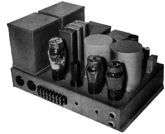
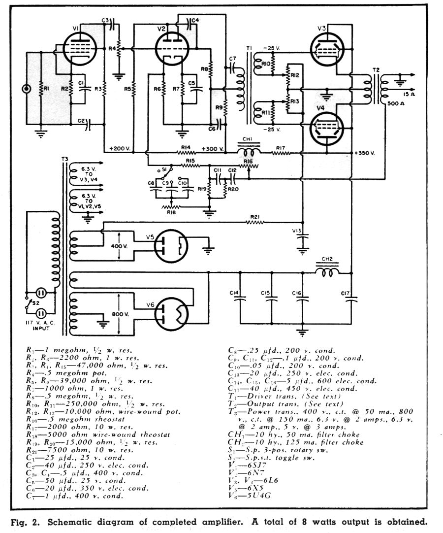
In Fig. 2, an amplifier using triode connected 6L6's as cathode followers is shown. A pentode is disadvantageous as a cathode follower as it interposes the problem of what to do with the screen. It cannot be tied to a positive potential as the cathode is swinging up and down with the signal which would, in effect, change the screen voltage and the mode of operation of the tube. 6B4's or 2A3's would be even better but they require a separate filament supply for each tube as the filaments are connected to each side of the output transformer. A cathode type is better in this case and there is reason to believe in the near future there will be a cathode type output triode on the market similar to the 2A3 or 6B4G. The 6L6 tubes are biased at approximately 25 volts and the plate current is approximately 60 mA per tube at 350 volts plate potential. This is slightly higher than the rated current, but is not high enough to heat the screens and does not damage the tubes. These 6L6 tubes are driven through a push-pull input transformer with a step-up ratio of 1 to 1.5, with only half the primary used. This transformer was chosen because it was available, and not because it was ideal for the job. A higher ratio would have been desirable. The practical effect is to limit the output because of less driving voltage. No attempt was made to extract maximum power from the 6L6's and they are operated under approximately class "A" conditions. The output was eight watts. Actually as much output as in the conventional amplifier is not needed because the distortion curve shows a very low distortion right up to the maximum output, and then a steep rise in distortion instead of a gradual rise in distortion from zero output to maximum output. It would have been desirable to drive with push-pull tubes, and if the builder has a push-pull interstage transformer this should be used.
Incidentally, the output transformer should have approximately the same impedance ratio as if the tubes were connected in the normal manner. The one the author used was 5000 ohms to 4-8 or 15 ohms; by hooking the 8 ohm speaker voice coil across the 15 ohm tap a ratio of 2500 ohms to 8 was obtained and this seemed to yield superb results. If this power output is insufficient there is another way of increasing it, better, perhaps, than increasing the driving voltage. Merely connect more output tubes in parallel as two additional 6L6's will double the power output with the same driving voltage. Or if four 6L6's are used, parallel triode connected, then approximately the same power may be obtained with a phase inverter, and the input transformer may be eliminated. Of course the power supply will have to stand the added current drawn by the additional tubes. The power supply in this model was rather elaborate not because it was necessary electrically but because the transformers were the only ones on hand. Actually an ordinary power transformer for 2A3's in push-pull with a bias tap will suffice. It should be capable of supplying about 350 volts at 150 mA, and a bias voltage of 25 or 30 volts, plus the filament requirements for the rectifiers and amplifier tubes.
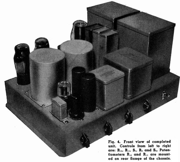
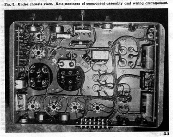
The photographs in Figs. 1, 3, and 4, show parts layout and wiring. The separate bias adjusting potentiometers RIZ and R13 (Fig. 2) are essential only if a high fidelity output transformer is used, so that the currents of the two tubes may be balanced within the limits specified by the manufacturer (usually 5 mA is considered permissible unbalance). The resistors are all mounted on resistor hoards which are neat, accessible, and rugged. Metal case condensers are used throughout as they provide admirable shielding. High and low frequency boosting controls are provided in a negative feedback circuit which also reduces the distortion in the preamplifier stages. The high frequency boost circuit allows a choice of high frequency boost points which are determined by the capacities C8, C9, and C10. This is useful for changing the response to suit different classes of fidelity, such as FM—AM—standard phonograph records, and short-wave. The high frequency cut-off should be reduced in the above order. The feedback net will vary with the quality of input and output transformers. R15 will have to be increased when inexpensive units are used. The smallest value which does not cause oscillation is correct. As the frequency of oscillation may be above audibility a small lamp connected to the output terminals will indicate oscillation by lighting. Be sure to connect the feedback lead to the proper side of the 500 output winding. If oscillation results, then reverse the cathode leads to the two output tubes. The 6SJ7 is triode connected and provides sufficient gain for any of the crystal pickups. The proper compensation network for the pickup used should be inserted between the pickup and the input. If the pickup puts out too much voltage, a series resistor of from 0.5 to 2 megohms will reduce it. As the volume control is not located in the input tube grid circuit, it is possible to overload the first tube. The control is located in the second tube to reduce the over-all hum level of the amplifier, which it does effectively. The hum, incidentally, cannot be heard with your ear placed several inches from the speaker. The large amount of negative feedback is instrumental in reducing it to this low level. Also, excellent filtering is provided in the power supply. This filtering is not so necessary from a hum standpoint, but is incorporated to reduce "motorboating" because of the amplifier's excellent low frequency response. If higher amplification is needed, the 6SJ7 may be pentode connected. Sufficient gain will result to allow the amplifier to be used with all the common types of microphones. The amplifier when finished should be turned on, and the bias adjusted to 25 Volts With the 6L6 tubes Out of, the sockets. Then plug in the tubes and connect the speaker and a radio or pickup. The improvement in fidelity will be immediately noticeable. The speaker that was used was of the eight dollar, 12-inch type for light duty service, mounted in a Jensen 15 inch bass reflex baffle. It gave results comparable to a 15-inch unit because of the low output impedance of the cathode followers. These cathode followers provide a fertile field for experimentation and even if an old power transformer is used for an output transformer the results will be gratifying, and considerably superior to one built using inexpensive transformers. A medium priced speaker will be transformed into a much better sounding one. Sounds like something for nothing, doesn't it? Well it is. END
User Guides for GlassWare Software
For those of you who still have old computers running Windows XP (32-bit) or any other Windows 32-bit OS, I have setup the download availability of my old old standards: Tube CAD, SE Amp CAD, and Audio Gadgets. The downloads are at the GlassWare-Yahoo store and the price is only $9.95 for each program. http://glass-ware.stores.yahoo.net/adsoffromgla.html So many have asked that I had to do it. WARNING: THESE THREE PROGRAMS WILL NOT RUN UNDER VISTA 64-Bit or WINDOWS 7, 8, and 10 if not 32-bit or any other 64-bit OS. I do plan on remaking all of these programs into 64-bit versions, but it will be a huge ordeal, as programming requires vast chunks of noise-free time, something very rare with children running about. Ideally, I would love to come out with versions that run on iPads and Android-OS tablets.
|
I know that some readers wish to avoid Patreon, so here is a PayPal button instead. Thanks. John Broskie
John Gives
Special Thanks to the Special 86 To all my patrons, all 86 of them, thank you all again. I want to especially thank
I am truly stunned and appreciative of their support. In addition I want to thank the following patrons:
All of your support makes a big difference. I would love to arrive at the point where creating my posts was my top priority of the day, not something that I have to steal time from other obligations to do. The more support I get, the higher up these posts move up in deserving attention.
If you have been reading my posts, you know that my lifetime goal is reaching post number one thousand. I have 489 more to go. My second goal was to gather 1,000 patrons. Well, that no longer seems possible to me, so I will shoot for a mighty 100 instead. Thus, I have 14 patrons to go. Help me get there.
Support the Tube CAD Journal & get an extremely powerful push-pull tube-amplifier simulator for TCJ Push-Pull Calculator
TCJ PPC Version 2 Improvements Rebuilt simulation engine *User definable
Download or CD ROM For more information, please visit our Web site : To purchase, please visit our Yahoo Store: |
|||||||||||||||||||||||||||||||||||||||||


| www.tubecad.com Copyright © 1999-2020 GlassWare All Rights Reserved |