| John Broskie's Guide to Tube Circuit Analysis & Design |
18 February 2020 Post Number 492
Class-G High-Voltage Regulator
Far more times than I would ever admit to in public, I have shorted the outputs. Big sparks, yet the regulator survived. How's that possible? Tubes live and thrive in high voltages, in addition, they are intrinsically current limited.
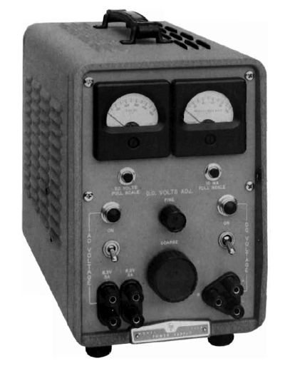
In contrast, solid-state devices are far more delicate when faced with high voltages, and they are capable of passing far more current, vastly more current than any tube. On the other hand, solid-state high-voltage regulators offer far better regulation and lower noise than their tube-based cousins do. Just as importantly, they can deliver gobs of current. My beloved HP 711A can only deliver 100mA, which isn't enough to test a tube power amplifier. In contrast, making a solid-state regulator that can pass 500mA is fairly easy. Making an adjustable high-voltage regulator is even more difficult, however, as the all-important pass device can see a huge voltage drop. For example, say we wanted a high-voltage regulator that could span between 10Vdc to 450Vdc and deliver up to 500mA. In order to get a reliable 450Vdc OpAmp voltage, the raw power-supply voltage would need to be about 500Vdc, which means that when regulator is putting 100Vdc at 500mA, the pass device must dissipate 200W. Good luck finding a pass device that robust or a heatsink large enough. Remember that unlike a 200W power amplifier, a voltage regulator must deliver DC voltage and current, not AC. Effectively, the regulator is a single-ended amplifier that puts out steady DC voltage. In other words, sustained high power dissipation is the rule, not the brief peak dissipation of 200W a power amplifier would be called upon to deliver.
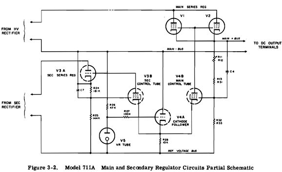
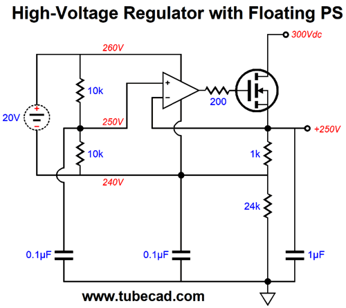
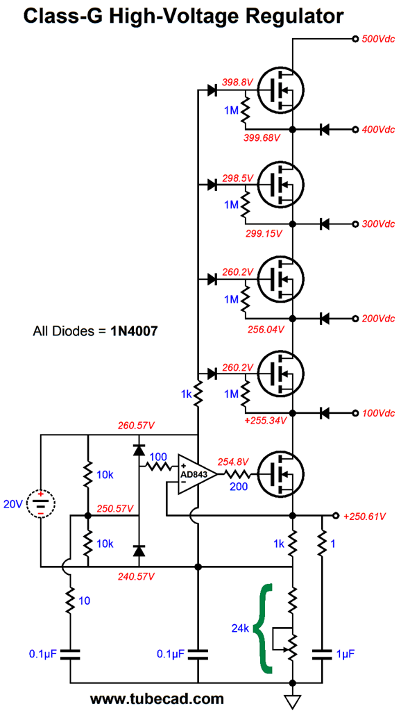
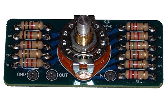
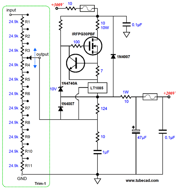
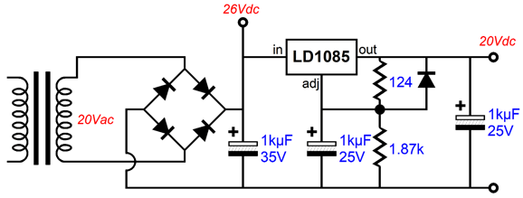
The workaround is to use a power transformer that holds a secondary with many taps, so the high-voltage regulator can choose the closest higher-voltage tap to the desired output voltage. For example, if you wanted 250Vdc, you would select the tap that produced a raw DC power-supply voltage of 300Vdc. In this example, 500mA at 250Vdc would only generate 25W of wasted heat, not the 125W that the 500Vdc of raw DC power-supply voltage would produce. (The HP 711A holds a secondary with three AC voltage taps.) The problem with this workaround is that a mechanical switching must be used to select the desired secondary tap and the raw DC power supply must charge either up or down to the target DC voltage. All electrical contacts are a potential problem, as a contact is thousands of times less reliable than a soldered joint. A PDF on the topic of contact reliability that well worth reading is "Critical Reliability Aspects of Electrical Contacts" by Piet van Dijk. A second problem is that the raw DC power supply must use high-voltage capacitors, even when the regulator's output voltage is low. At least a 10% safety margin should be employed when selecting capacitor voltage ratings. For example, if the maximum DC voltage is 500V, then a 550V capacitor should be used—and 600V would be safer still. Although I have seen 600V electrolytic capacitors, most top out at 500V. One workaround is to use two 300V capacitor in series with each capacitor shunted with a bleeder resistor, usually a 100k/3W resistor, which ensures an equal voltage division between capacitors and a means of de-energizing the capacitors at turn-off. But the biggest hassle with the multi-tapped power transformer is actually finding a source for it. Most likely, you won't, so you will have to have a custom transformer wound. My alternative circuit seeks to avoid the mechanical switching, the high-voltage capacitors, and the multi-tapped power transformer. The sneaky aspect of the design is its class-G structure, which uses diodes in place of switches and many relatively low-voltage raw DC power supplies in series rather than a single raw DC power supply. First, let's look at the regulator topology. Here we see a fixed raw DC power supply voltage of 300V and a regulator output voltage of 250V. The N-channel MOSFET serves as the pass device. In other words, the MOSFET must pass all the current into the external load. An OpAmp controls the MOSFET, and the OpAmp is power by a floating 20V regulated power supply. Because the 20V power supply is regulated, we can use its fixed 20V as the high-voltage regulator's voltage reference—after the 20V is halved by the two-resistor voltage divider made up of the two 10k resistor in series. The MOSFET's 1k source resistor will always see a constant 10V voltage drop, as the OpAmp monitors the voltage drop and compares it to the voltage drop across the bottom 10k voltage-divider resistor. As the 1k sees a fixed DC 10Vdc voltage drop, it also experiences a fixed current flow of 10mA. In turn, the 10mA current flow travels through the 24k resistor and develops a voltage drop of 240Vdc across the resistor, resulting in a voltage of 250V at the regulator's output, as 10V and 240V voltage drops added together to make 250Vdc. The three capacitors help eliminate noise and improve high-frequency performance. Effectively, the high-voltage regulator is a unity-gain power buffer whose input signal is ground, albeit voltage shifted upwards. The next step is to include the class-G functionality. Here five 100V power supplies are wired in series. The five N-channel MOSFETs allow easy switching between raw power supply voltages. The diodes at the MOSFET gates and sources allow us to select automatically the needed raw power-supply voltage tap and which MOSFETs should be turned on or off. The two diodes in the OpAmp circuit are there to protect the OpAmp from seeing excessive voltages. The potentiometer permits us to choose the desired output voltage. Of course, I would never actually use a potentiometer, preferring to use a rotary switch and many power resistors. The key-word in that last sentence was "power." With an output voltage of 450V, the bottom resistance must equal 44k, which against the 10mA of current flow results in a dissipation of 4.4W, far too much for any normal potentiometer, but not too much for 10 resistors, as each would experience only 0.44W of dissipation. In fact, I would use two of my mono Trim-1 stepped attenuators, which offer 11 steps.
The attenuation is a series type, wherein 11 resistors are placed in series and a rotary switch selects the desired junction. Here is an example from post 226:
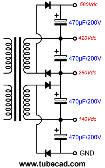
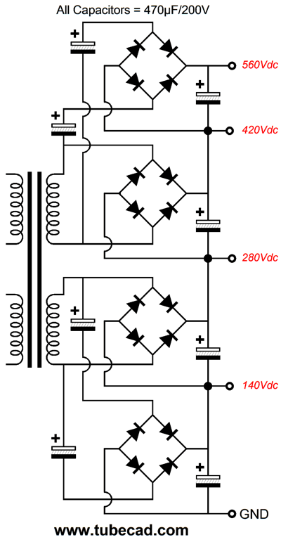
In this design example, in contrast, I would set up coarse voltage increments of 10V, 50V, 100V, 150V, 200V, 250V, 300V, 350V, 400V, 450V, and 475V for the first Trim-1 and fine voltage increments of 0V, 5V, 10V, 15V, 20V, 25V, 30V, 35V, 40V, 45V, and 50V for the second Trim-1. With these two series attenuators, we could select any from 10V to 450V in 5V increments. Of course, we could add a third Trim-1 and make even finer voltage increments of 0V, 0.5V, 1V, 1.5V, 2V, 2.5V, 3V, 3.5V, 4V, 4.5V, and 5V. I would add a digital voltage meter readout, which cost about $20. The raw DC power supplies could be made from five power transformers or from three transformers with dual secondaries or one transformer with two 100Vac secondaries. Here we see four voltage taps, 140, 280V, 420V, and 560V. The 100Vac secondaries feed voltage-doubler rectifier circuits that charge up 200V reservoir capacitors. The danger with this rectifier arrangement is that we risk transformer saturation due half-wave rectification on half of the voltage doubler.
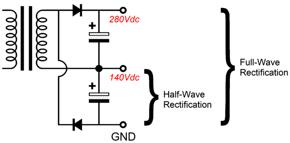
In the above example, drawing 500mA from the 140Vdc tap will result in unidirectional charging of the bottom capacitor and potentially magnetizing the core. In contrast, if we draw 500mA from the 140Vdc tap, we sidestep the problem of unidirectional rectification, as the full-wave rectification takes advantage of both cycles of the sinewave. The workaround is to go for full-wave voltage doublers.
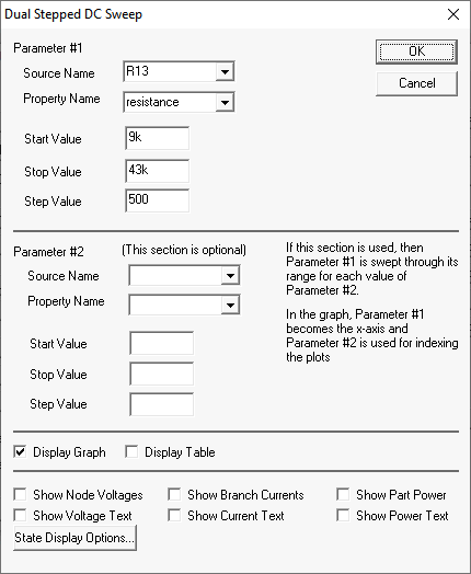
Or, we could have used two transformers with dual 50Vac secondaries, which would halve the voltage across each capacitor and even further limit the heat dissipation from the pass device. I had to fight SPICE to get this circuit to work well. Oddly enough, this often happens in SPICE when dealing with floating power supplies and OpAmps. A few times I have encountered the odd situation where a circuit that works wonderfully in reality but fails to work in SPICE; this is odd, as the inverse, wherein the SPICE circuit works great in SPICE but not in reality, proves far more common. In both exceptions, the usual cause is that real resistors, capacitors, inductors are not ideal, as each incorporates its own failings. For example, SPICE capacitors do not present ESR or ESL (effective series resistance and effective series inductance); SPICE resistors are all of 0.000000000001% tolerance and present no inductance or capacitance; SPICE inductors are free from DCR and capacitance. With this circuit, it possible that some of the SPICE OpAmp models make internal connections to ground, which would never happen in an actual floating design. My big fear with this design is that we might encounter voltage gaps, where no high-voltage MOSFET is turned on, as the desired DC output voltage missed the needed turn-on voltage for the MOSFET. Indeed, with other part values, I did encounter such voltage gaps. Here is a graph of the relationship between output voltage and the voltage-setting resistor value. No gaps that I can spot. But that doesn't mean we will not encounter some in reality. (Perhaps if I had used finer resistance increments of 100 ohms, we would have spotted some voltage gaps.)
Okay, I just tried 100-ohm steps and I did encounter voltage dropouts. A workaround would be to place a toggle switch on the front panel that switched from the regulated 20V floating power supply voltage to its raw DC power supply voltage to drive the MOSFET gates, which would have to be at least 4V higher than the output voltage—or else the regulator would be voltage starved. In SPICE simulations, the two voltages produced gaps, but not at the same output voltage, the toggle switch solution would work.
I have been sitting on this design for over a decade. Perhaps it isn't ready for production yet. Nonetheless, the seed idea is compelling. Another perhaps is that maybe the better approach would a class-H effort, wherein the raw power supply voltage ramps up and down with need by using a variable-DC switching regulator. Or, maybe employing mechanical switches makes more sense. By the way, I have designed and built many pieces of test equipment. It's fun. It differs from audio gear in that evaluating it is not a subjective effort. A high-voltage regulator must deliver a sustained DC voltage with low output impedance and noise. Ease of use, however, falls into subjective evaluation.
Better-Balanced G–K Output Stage
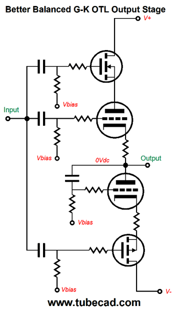
I gave the topology the clumsy name of "grid-cathode push-pull output stage," which is certainly descriptive but not memorable. (In fact, I had forgotten it.) What makes this circuit so interesting is that it is a push-pull tube output stage that doesn't need a phase splitter, as it accepts a uni-phase input signal. The Lazy Three (White cathode follower, SRPP, and SRCFPP) do as well, but they all hold a current-sense resistor that creates the needed anti-phase signal. In addition, the Lazy Three must be run in strict class-A and must be optimized for a specific load impedance. In contrast, the grid-cathode push-pull output stage can run in class-A, AB, B and is load impartial. I knew that since the bottom output tube was being driven in a grounded-grid amplifier configuration, the cathode's greater transconductance would imbalance the current swings between top and bottom output tubes, which explains why I used a cathode resistor only on the bottom output triode. This works, but it is clumsy and results in an unsymmetrical output impedance between top and bottom output triodes. The better approach is to force symmetry between output triodes in terms of cathode-to-plate voltages.
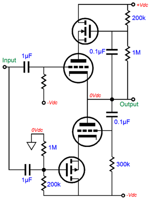
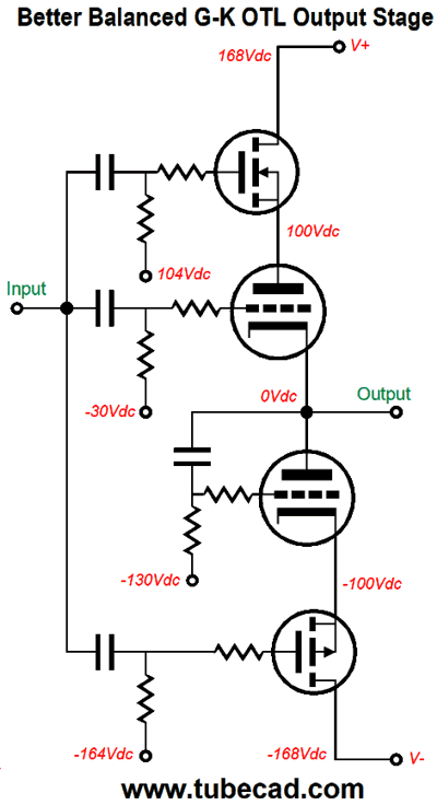
We find the big change in the top MOSFET, as it no longer is driven by the output signal, but by the output stage's input signal. Now, the N-channel MOSFET, P-channel MOSFET, and top triode all see the same input signal. The bottom triode still sees the output signal at its grid. Let's flesh-out the circuit with essential parts and typical voltages.
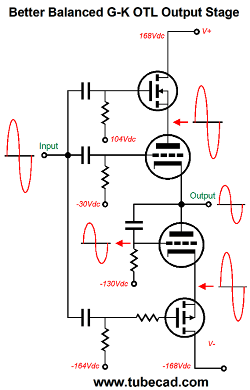
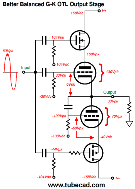
The +/-168Vdc bipolar power supply is the result of rectifying a 240Vac center-tapped secondary. At idle each triode sees the same 100V cathode-to-plate voltage and the same idle current flow. Let's look at the signal relationships.
A large input signal results in a much smaller output signal due to the triode's weak transconductance and the loudspeaker's 8-ohm impedance. What might not be seen readily is that the triodes see inverse-symmetrical cathode-to-plate voltage swings, and both triodes see equal but anti-phase input signals.
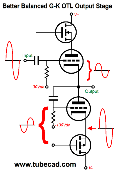
The top triode does not see the full input signal, as the output signal must be subtracted from the input signal. The bottom triode sees an equal inverted signal, as its cathode sees the full input signal, while its grid sees only a portion of the input signal; thus, its grid effectively swings in an inverted fashion relative to its cathode. Since this is a key point, let's downshift and examine the instantaneous voltage relationships when to the peak input signal reaches 60V.
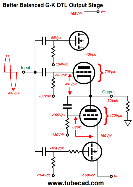
Now, compare this to when the peak signal reaches -60V.
Note the symmetry. Both triodes undergo equal peak-to-peak cathode-to-plate voltage swings. Both grids see equal peak-to-peak grid-to-cathode voltage swings. Symmetry prevails. We can no longer say that the bottom triode is being operated in a grounded-grid-amplifier fashion; thus, there is no longer any need for the bottom triode cathode resistor to undermine the bottom triode's transconductance. Thus, an equal output impedance between triodes obtains. Imagine a positive voltage pulse forced upon the output. The top triode's cathode is pushed positively, while its grid sees no change in its voltage, so effectively the grid becomes more negative relative to the its cathode, causing the top triode to conduct less current. In addition, the top triode sees less cathode-to-plate voltage, which also leads to less current flow. At the same time, the bottom triode sees both its plate and grid voltages rise, while its cathode remains fixed, causing the triode to conduct more. These two alterations in current flow buck the positive pulse. If a 1V pulse causes the top triode(s) conduction to drop by 500mA and the bottom triode(s) conduction to increase by 500mA, a net change of 1A, the output impedance would be 1 ohm. All in all, I view this variation on the grid-cathode push-pull output stage ("GKPP"perhaps might be a better name) to be a sound improvement. Not mentioned this time, but was mentioned in post 399, is that the two MOSFET also function as free voltage regulators of sorts, as they shield the triodes from the power-supply noise. Moreover, I should mention that the triodes are partially plate driven. Go back and look over the schematics that shows the show the voltage relationships due to +60Vpk and -60Vpk input signals. For example, when the input signal peaks at 60V, the output climbs to 30V, and the top triode's cathode-to-plate voltage climbs to 130V, 30V more than at idle. When do triodes stall at deliver high current? When their cathode-to-plate voltage drops. But in this topology, the cathode-to-plate voltage increases, when the current demand increases. See post 288, wherein I write about magic wallets and OTL output stages. Making an actual power OTL with the GKPP output stage requires placing many output triodes in parallel. With 6AS7/6080 output tubes, I would use eight tubes per channel, a total of sixteen triodes, which would allow 100W of power output into 8-ohm loads. What about 4-ohm loudspeakers? Don't, just don't use them with any OTL. Indeed, if you can find a 16-ohm loudspeaker, all the better. Do not forget that tubes are current limited, not voltage limited.
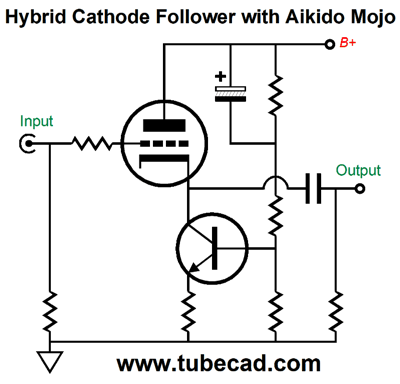
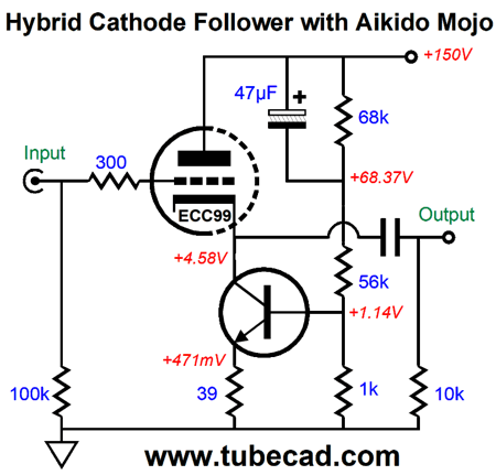
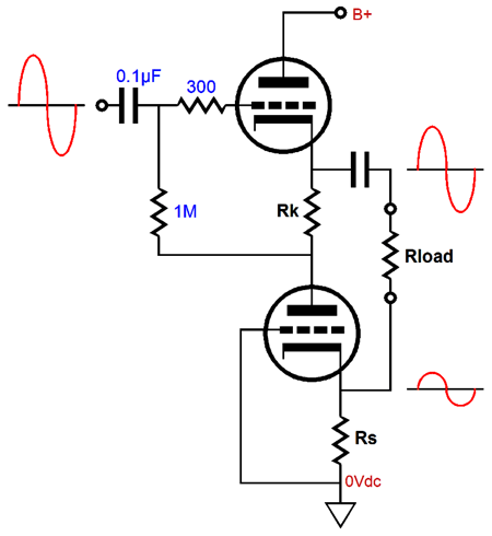
The cathode follower's input is at ground potential, so no input coupling capacitor is needed. The NPN transistor works as a constant-current source with a twist, as its current flow is modulated by the B+ voltage ripple, causing the cathode follower to effectively ignore the ripple, making for a better PSRR figure. Here is the same circuit fleshed out with part values. The ECC99 triode idles at 12mA and the NPN transistor's emitter resistor only loses 0.47 volts across its leads. This robust hybrid cathode follower could easily drive long lengths of high-capacitance interconnects or even high-impedance headphones. Because of its single-ended design, the peak output current swing would equal the idle current; in this design example, 12mA, with 10mA being a more realistic assumption. Now, 10mA against a 300-ohm load impedance equal a peak voltage swing of 3Vpk, three times that put out by an iPod. Long ago, when I owned Sennheiser HD580 headphones, I conducted a test. I played the music as loud as I could comfortably withstand, then I measured the peak voltage swings on a scope. I saw peaks of only 3V. Of course, others might desire even more potential voltage swing. In this case, a higher idle current and B+ voltage would be needed (or an input coupling capacitor with just higher idle current).
As I looked the circuit over, I wondered if I couldn't create an SRCFPP out of it. The SRCFPP is my contribution to the Lazy Three trinity of White cathode follower, SRPP, and SRCFPP. Like its brother circuits, it is a push-pull output stage that gets away with an unbalanced input signal by using a current-sense resistor to create the needed anti-phase signal for the triode that doesn't get the input signal. Unlike its two brother circuits, its output is balanced. In other words, we would have to use a four-contact plug and jack to connect to the headphones, not the typical three-contact types.
The NPN transistor's emitter resistor is the current-sense resistor, as a varying current flow through this resistor will cause a varying anti-phase current flow through the transistor. The next step was to add my some of my signature Aikido mojo.
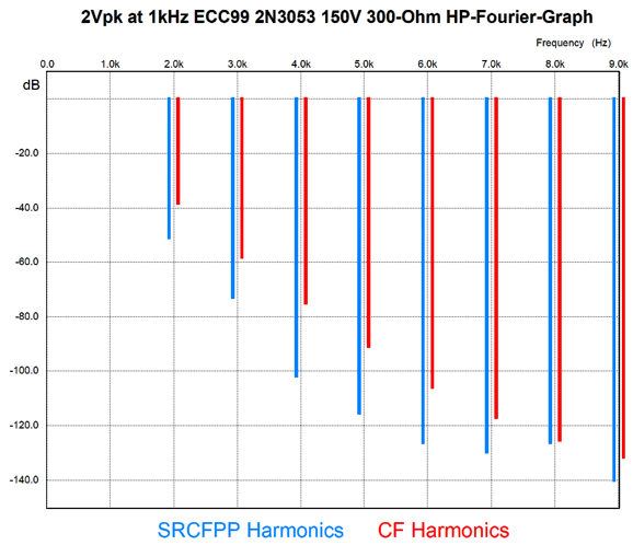
The 68k and 1k resistors define a two-resistor voltage divider that delivers a small portion of the B+ voltage noise to the transistor's base, which forces a power-supply noise null at the output. The 16-ohm emitter resistor undoes much of the NPN transistor's transconductance, bringing it in line with the triode's. The 47µF may seem excessive, but it isn't, as we want the PSRR enhancement to extend deep into the lower frequencies. So, how do these two hybrid followers compare in performance? Here is the results from SPICE simulations with 2Vpk output at 1kHz into a 300-ohm load. As you can readily see, the SRCFPP wins, as it delivers lower distortion.
Music Recommendation: The album contains the works of five composers, all were Jewish, all but one died during WWII. Mieczysław Weinberg escaped the Nazis, but would have been murdered by the Soviets had Shostakovich not wrote letters in his defense.
The compositions are modern, but not annoyingly modern. You know that I am going to point out that Tidal offers album, so I don't need to.
//JRB
User Guides for GlassWare Software
For those of you who still have old computers running Windows XP (32-bit) or any other Windows 32-bit OS, I have setup the download availability of my old old standards: Tube CAD, SE Amp CAD, and Audio Gadgets. The downloads are at the GlassWare-Yahoo store and the price is only $9.95 for each program. http://glass-ware.stores.yahoo.net/adsoffromgla.html So many have asked that I had to do it. WARNING: THESE THREE PROGRAMS WILL NOT RUN UNDER VISTA 64-Bit or WINDOWS 7 & 8 or any other 64-bit OS. I do plan on remaking all of these programs into 64-bit versions, but it will be a huge ordeal, as programming requires vast chunks of noise-free time, something very rare with children running about. Ideally, I would love to come out with versions that run on iPads and Android-OS tablets.
|
I know that some readers wish to avoid Patreon, so here is a PayPal button instead. Thanks. John Broskie
John Gives
Special Thanks to the Special 84
I am truly stunned and appreciative of their support. In addition I want to thank the following patrons:
All of your support makes a big difference. I would love to arrive at the point where creating my posts was my top priority of the day, not something that I have to steal time from other obligations to do. The more support I get, the higher up these posts move up in deserving attention.
If you have been reading my posts, you know that my lifetime goal is reaching post number one thousand. I have 508 more to go. My second goal is to gather 100 patrons. I have 16 patrons to go. Help me get there.
Only $9.95
The Tube CAD Journal's first companion program, TCJ Filter Design lets you design a filter or crossover (passive, OpAmp or tube) without having to check out thick textbooks from the library and without having to breakout the scientific calculator. This program's goal is to provide a quick and easy display not only of the frequency response, but also of the resistor and capacitor values for a passive and active filters and crossovers. TCJ Filter Design is easy to use, but not lightweight, holding over 60 different filter topologies and up to four filter alignments: While the program's main concern is active filters, solid-state and tube, it also does passive filters. In fact, it can be used to calculate passive crossovers for use with speakers by entering 8 ohms as the terminating resistance. Click on the image below to see the full screen capture.
Tube crossovers are a major part of this program; both buffered and un-buffered tube based filters along with mono-polar and bipolar power supply topologies are covered. Available on a CD-ROM and a downloadable version (4 Megabytes). Download or CD ROM
|
|||


| www.tubecad.com Copyright © 1999-2020 GlassWare All Rights Reserved |