| John Broskie's Guide to Tube Circuit Analysis & Design |
20 November 2017 Post Number 402
Special Thanks to the Special 61
If you have been reading my posts, you know that my lifetime goal is reaching post number one thousand. I have 598 more to go. My second goal is to gather 1,000 patrons. I have 939 patrons to go. If you enjoyed reading this post from me for the last 18 years, then you might consider becoming one of my patrons at Patreon.com. It would make a big difference to me. Thanks.
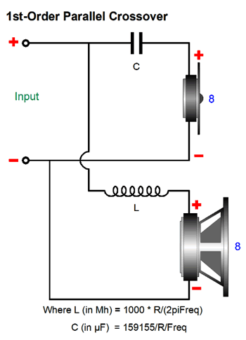
Series Vs Parallel Crossovers
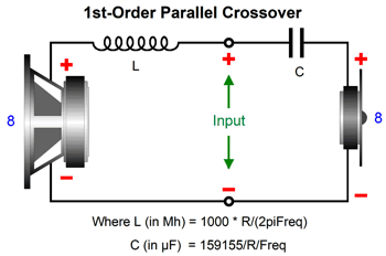
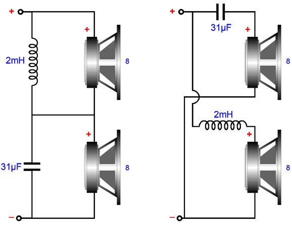
If we redraw the above schematic, the parallel nature is more easily seen.
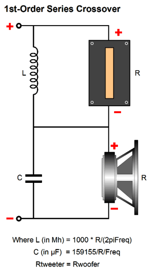
An alternative crossover type is the series type, where each driver sees its own separate input and ground connections, as shown below.
Both of these crossover types so far shown offer the same low-pass filtering for the woofer and high-pass filtering for the tweeter. In SPICE simulations, no distinctions between the two crossover types can be discerned.
But then, SPICE simulations of crossover usually use resistors, not actual loudspeaker drivers. Real speaker drivers, in sharp contrast, are nothing like a SPICE resistor model. Does this make a difference? I believe it does, possibly a big difference. About 30 years ago, I knew an electrical engineer with a PHD from Stanford, whose doctoral dissertation was on electronic filters; he had retired from Hewlett Packard and was devoting his efforts to loudspeaker crossovers. He told me that after years of analysis and experiment no crossover—no matter how elaborate and complex—could beat the simple, first-order series crossover. His theory was two-part: first, any crossover order higher than the first must give rise to phase aberrations; and, second, by shunting the loudspeaker drivers with capacitors and inductors in the series crossover the drivers see needed dampening where they needed it most, i.e. outside their bandwidth limits. In other words, the woofer gets shunted by the capacitor's falling impedance as the frequency extends beyond its high-frequency range, just as the tweeter gets shunted by the inductor's falling impedance at the tweeter's resonant frequency. In contrast, he argued, in the parallel crossover, the woofer becomes unloaded at high-frequencies, as the inductor's increasing impedance decouples the woofer from the amplifier's low output impedance. (Goodbye damping factor of 2,000.) And the tweeter finds no useful damping resistance at its resonant frequency, as the crossover capacitor's impedance has climbed to too high a value to prove useful. Was he right? I have always been inclined to agree with him, but how can we devise a test to prove him either right or wrong? My answer is to take two fullrange drivers and arrange them with both types of crossover and hold a shootout. A shootout with a single fullrange driver and a shootout between the two crossover types.
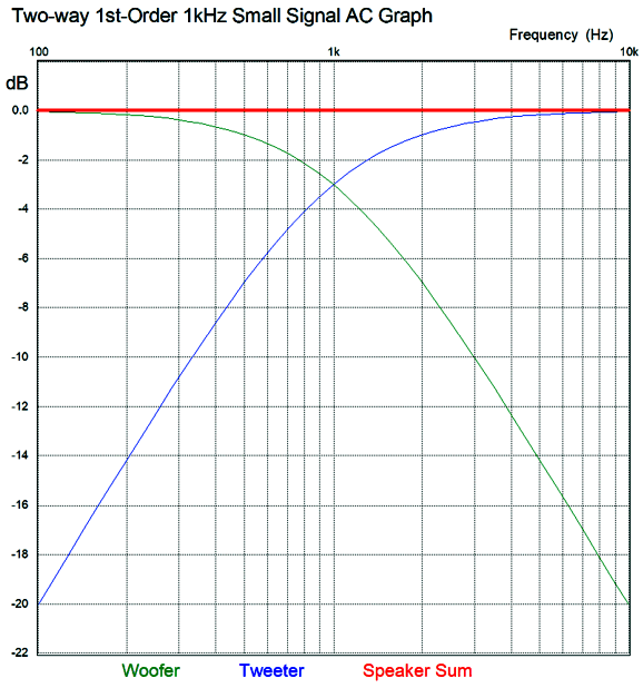
The huge problem with first-order filters is that cut-off slope isn't very steep; indeed, it's shallow, falling off at only -6dB per octave and -20dB per decade. This requires that the both drivers exhibit much wider bandwidth than we are likely to encounter in reality. The speaker industry's solution is to use higher-order, steeper crossovers, such as 2nd, 3rd, and 4th order crossovers. The drivers are happier with less work to do, but we lose phase-flat performance. A square wave goes in and nothing like a square wave comes out. By the way, if you read the literature on crossovers, you read that phasing is unimportant with first-order crossovers, as the woofer and tweeter differ by 90 degrees at the crossover frequency, so no matter how the tweeter is phased relative to the woofer, the same flat frequency response results. Bad advice. The mistake made was to only consider frequency response, not transient response. Look at the graph below and note what happens to a tone burst that is 3mS long and contains exactly three cycles. With the two drivers in phase, we get the perfect tone burst; with the drivers out of phase, we still get a flat frequency response, but a slurred tone burst.
Transient response describes how a system reacts to a change from either being in a state of equilibrium or in a steady state. In other words, how an electrical circuit or loudspeaker responds to the beginning of a signal or the cessation of the signal is its transient response. In days past, measuring a loudspeaker's actual transient response was difficult; in contrast, measuring its frequency response was easy. So much like the joke about the drunk man who looks for his lost car keys not where he dropped them, but under the streetlight where the light was better, many just ignored transient response and phase. The problem is that a loudspeaker can measure a perfectly flat frequency response and sound dreadful. Back in the late glory days of Home Audio, Richard C. Heyser wrote series of great articles for Audio magazines, wherein he tried to convince us to stop treating frequency response as the only important criteria for evaluating audio gear. Sadly, most of my friends told me that his articles made their heads hurt. Here is an example:
Heyser quote from June 1977 Audio Magazine I am tempted to stand up and shout, "Testify, Richard, testify," but at the same time I know that words like "codetermination" and "parameters" in this quotation have already put many off reading anymore from Mr Heyser, alas.
2nd-Order Crossovers
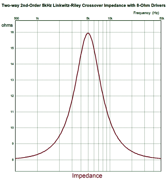
In the first-order crossover, the crossover frequency undergoes a phase shift, so the drivers see a net 90 degree difference at this frequency. If you do the math, you see that -3dB (70.7% of the input signal) and 45 degrees of phase shift per driver sum up to 0dB and zero degrees of phase shift. But in the second-order crossover, the crossover frequency undergoes a 180-degree phase shift between drivers. Thus, if the drivers are hooked up in phase, a deep null will appear at the crossover frequency. If we invert the tweeter's phase, the two drivers sum to 0dB and 90-degrees of phase shift at the crossover frequency from both drivers. Prior to the advent of the Linkwitz-Riley crossover alignment, the second-order Butterworth was used, which resulted in a +3dB boost at the crossover frequency and 90-degrees of phase shift. Something that almost no one mentions is that the Linkwitz-Riley crossover alignment does not produce a flat impedance across the speaker's audio bandwidth, as the impedance will double at the crossover frequency.
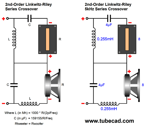
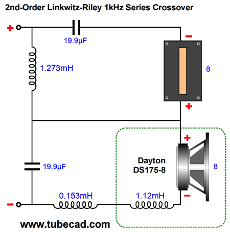
Is this a problem? In general, no, at least not with most solid-state power amplifiers. It can be a problem with a tube-based power amplifier without a negative feedback loop, which somewhat straddles both voltage-out and current out amplifier types, with triode-based being closer to voltage-out; pentodes, current-out. And it certainly will prove to be a huge problem for current-output power amplifier, no matter the output devices used. Why? The current-output power amplifier puts out a set amount of current, while the voltage-output power amplifier puts out a set amount of voltage. So, if the current-output amplifier encounters twice the impedance, it will put out the same amount of current, which means that it will also put out twice the voltage. The result will be a +6dB boost at the crossover frequency. Of course, if you are using active electronic filters and bi-amping, then both amplifiers will see 8-ohms. (Just another reason why bi-amping makes so much sense.) I have never seen the Linkwitz-Riley crossover alignment applied to the series crossover topology, so I had to roll my own. It wasn't hard.
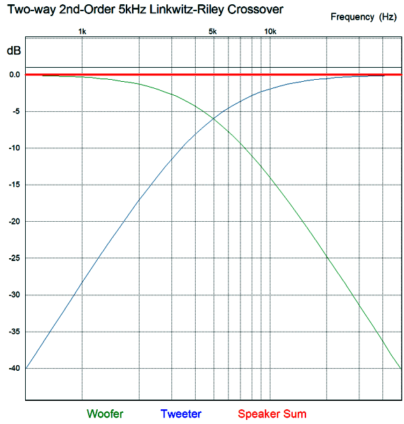
Note that the capacitor and inductor values are the same as in the first-order crossover. The results from SPICE simulations are identical to the parallel version: the same the woofer and tweeter summing to a flat frequency response, the same impedance plot—nothing different from the Linkwitz-Riley parallel crossover. Now for the SPICE transient response test.
Far better than I expected. The tone burst only lasted for 1 millisecond and completed five cycles at 5kHz at 1Vpk. This was the sum for both drivers, but what does each driver's output look like?
Note that both drivers are still moving after the tone burst ended at 2mS, or rather the capacitors and inductors were slow to release their stored energy. Now that we have both a parallel and series Linkwitz-Riley crossover alignment, we should pause and evaluate them both. Unlike the first-order versions, the second-order series crossover places a capacitor in series with the tweeter and an inductor in series with the woofer, which will undo the shunting effect that having these reactive devices in parallel with the drivers. On the other hand, placing the inductor in series with the woofer allows us to overcome a problem that many never think about: namely, the woofer's own internal series inductance, which can be considerable.
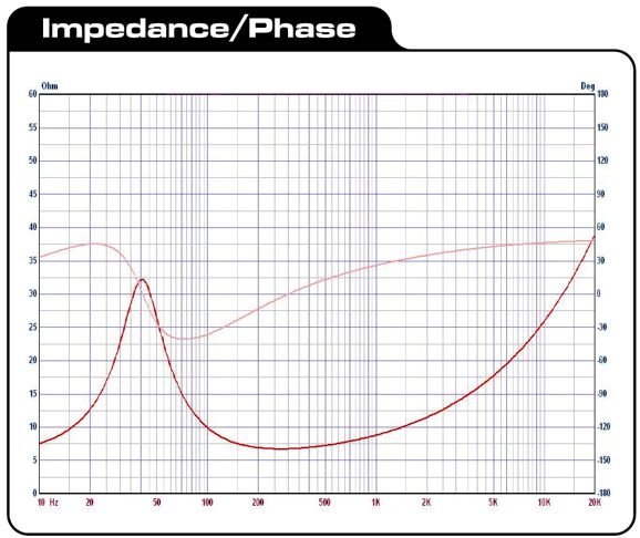
If you look through a woofer's data-sheet specifications, you will find an entry labeled "Le" that stands for the woofer's own inductance. As long as this value is less than the crossover specified inductor value, we can subtract the woofer's Le from the crossover inductor value. If the woofer's value is greater, then a lower crossover frequency must be used. Here is the Dayton DS175-8 woofer impedance and phase plots.
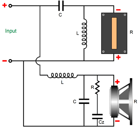
Note that the driver only touches 8-ohms at 10Hz and between 250Hz to 300Hz, yet we refer to it as a nominally 8-ohm design. With the parallel Linkwitz-Riley second-order crossover, we must neutralize the woofer's own internal inductance with a Zobel network, which consists of a resistor equal to the driver's impedance and a capacitor, whose value will undo the woofer's inductance.
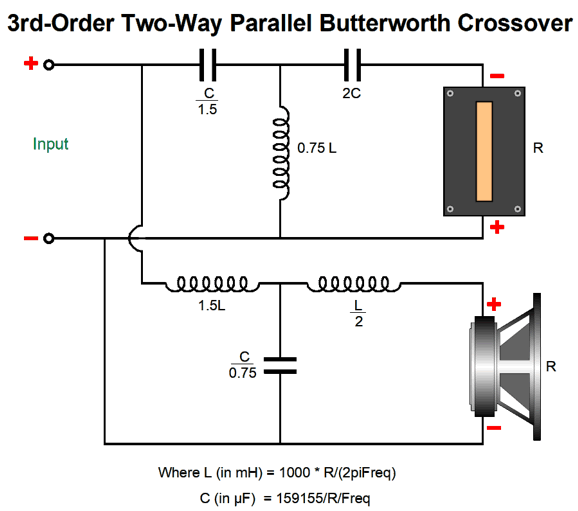
3rd-Order Crossovers
The transient response, however, gets a bit confused.
Note the inverting phase on the tweeter; this is essential. Once again, in the literature on crossovers, tweeter phasing is regarded as unimportant with third-order crossovers, for the woofer and tweeter differ by 90 degrees at the crossover frequency. Once again, no matter how the tweeter is phased relative to the woofer, the same flat frequency response results. But what happens to the transient response if the tweeter's phase isn't inverted? Here is the result:
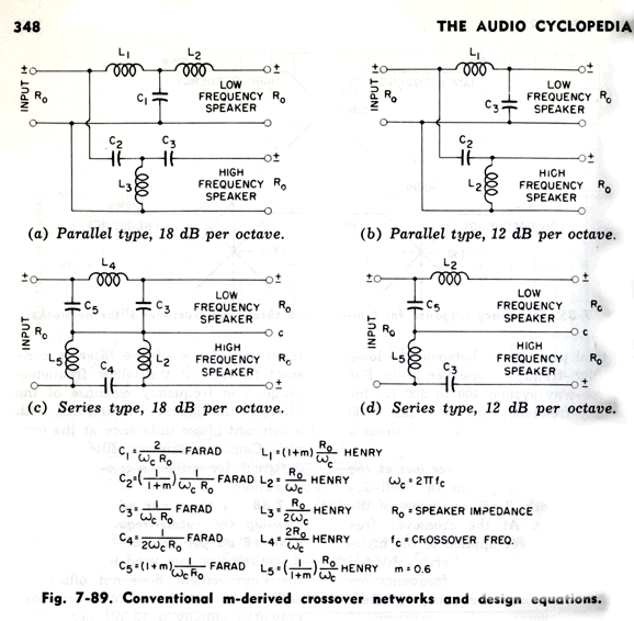
Three cycles become five cycles. Which would you rather listen to? How do we convert the third-order parallel crossover to a series crossover? Google was surprisingly empty-handed with this search. Fortunately, my own electronics library was more useful. Doubly fortunately, the book I sought, Howard M. Tremaine's massive book, Audio Cyclopedia, was not hidden in one of the many boxes of books, but on my remaining bookcases. (When we finished our basement, I lost half of my bookcases, but not half my books.)
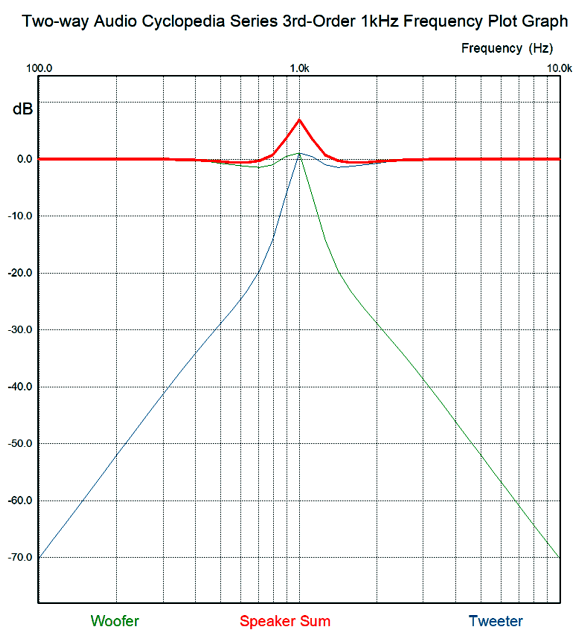
Unfortunately, the crossover ratios described in this book do not work well. For example, here are the resulting frequency response plots.
Here is the impedance plot.
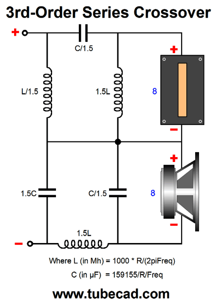
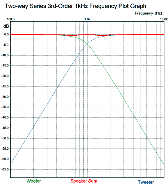
I went digging through my notes and found my own set of ratios.
The problem here is that I derived these ratios from my own mathematical intuition, which is a mixed blessing. How so? If you are taking a math test and the teacher expects to see your work, you have to waste time creating the work that you didn't need or else get marked down. On the other hand, if you are taking a multiple-guess math test or an IQ test, then you can soar. Another problem with intuition is that when you are wrong, it is hard to see where you went wrong; and even when you are right, it can be hard to see how it is that you are right. Sir Isaac Newton was an intuitive genius, and many of his best advances came to him as intuitions. He was, moreover, a brilliant mathematician who could—after his flash of intuition—come up with a rigorous logical and mathematical explanation of how he got there. I am not so gifted. Well, my intuition-derived ratios work far better in SPICE simulations, but not perfectly.
The impedance peaks at 11 ohms at the crossover frequency. To truly have arrived at equal performance to the parallel 3rd-order crossover, the impedance would have to be a flat 8-ohms across the audio band. And as I now look at the schematic, my intuition is that the shunting capacitor and inductor should equal the first-order values; SPICE disagrees, however. No doubt, if I were forty years younger, I could work out the hard math and get the exact ratios needed. (Dimly, I remember 0.5 and 0.866 and 1.0 being key numbers in a third-order Butterworth filter alignment.) My hope is that someone like Chris Paul can make more sense out of this puzzle.
Electrostatic Ideas, More Still
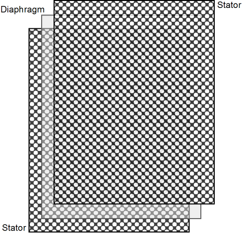
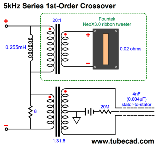
Interestingly enough, many ribbon tweeters present so low an impedance that a step-down transformer is needed. Fortunately, the higher the frequency passed, the smaller the transformer can be. In addition, the lower the secondary load impedance, the happier the transformer is and the lower the distortion from the transformer is—all of which, implies that a low-DCR ribbon is the best way to go. For example, the Fountek NeoX3.0 ribbon tweeter's diaphragm's impedance is just 0.02 ohms. Internal to the tweeter is an audio transformer with a winding ratio of 20:1, which implies an impedance ratio of 400:1, which in turn allows the power amplifier to see an 8-ohm load. The voltage ratio is 20:1 and the current ratio is 1:20, so 1A in becomes 20A at the ribbon. Interestingly enough, the Fountek's own internal transformer presents so low a primary DCR that a series capacitor must be used, even when bi-amping. Why? Let's say the DCR is 0.001 ohms and the amplifier presents a DC offset of just 10mV. Do the math: 0.01V / 0.001 ohms equals 10A. In the above schematic, we need not worry about the low primary DCR, as the 8-ohm power resistor is in series with it. If we are bi-amping with a tube power amplifiers, no DC offset occurs, so we need not worry. (It is still a good idea to use a coupling capacitor with the tweeter, no matter what the design, in a bi-amp system, as 60Hz hum and buzz can kill a tweeter in seconds. Just pick a capacitor value that crosses over a decade lower than the electronic crossover frequency. For example, if the electronic crossover frequency is 3kHz, use a 68µF capacitor, which will crossover at about 300Hz.) I love the idea of a speaker hold both step-up and step-down transformers. Note that DC offsets from the power amplifier may saturate the transformers, but the ribbon and the electrostatic woofer are safe. The electrostatic speaker does not load down the power amplifier at low frequencies, as its impedance is so very high, much like the capacitor in the schematic below.
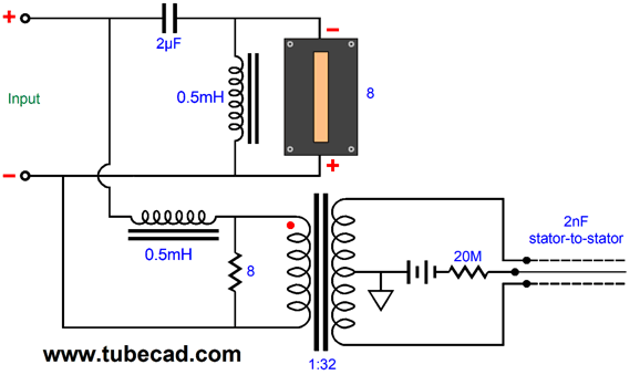
By replacing the woofer with an electrostatic speaker we also replace the crossover capacitor, as the electrostatic speaker is a capacitor. What is missing in the swap is resistance, which the added 8-ohm resistor supplies. This resistor must be a large power type, preferably a non-inductive design. The electrostatic speaker's step-up transformer holds a winding ratio of 1:31.6, which implies a capacitance ratio of 1,000:1, so the 4nF is reflected as 4µF. If we desire a steeper crossover slope, the second-order parallel crossover would work best, as we need to have a resistance shunted by a capacitor. Here is a 5kHz crossover.
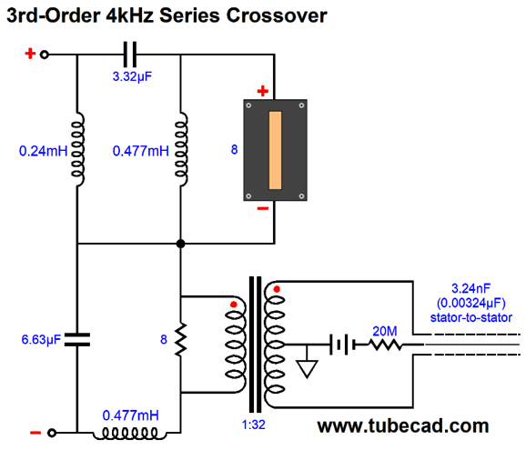
If we wish to go even steeper, then the 3rd-order series is our best choice.
The electrostatic speaker becomes magnified by a thousand fold by the step-up transformer, so the 8-ohm resistor is shunted by 3.24µF of capacitance.
//JRB
If you enjoyed reading this post from me, then you might consider becoming one of my patrons at Patreon.com.
User Guides for GlassWare Software
For those of you who still have old computers running Windows XP (32-bit) or any other Windows 32-bit OS, I have setup the download availability of my old old standards: Tube CAD, SE Amp CAD, and Audio Gadgets. The downloads are at the GlassWare-Yahoo store and the price is only $9.95 for each program. http://glass-ware.stores.yahoo.net/adsoffromgla.html So many have asked that I had to do it. WARNING: THESE THREE PROGRAMS WILL NOT RUN UNDER VISTA 64-Bit or WINDOWS 7 & 8 or any other 64-bit OS. I do plan on remaking all of these programs into 64-bit versions, but it will be a huge ordeal, as programming requires vast chunks of noise-free time, something very rare with children running about. Ideally, I would love to come out with versions that run on iPads and Android-OS tablets. //JRB |
E-mail from GlassWare Customers
High-quality, double-sided, extra thick, 2-oz traces, plated-through holes, dual sets of resistor pads and pads for two coupling capacitors. Stereo and mono, octal and 9-pin printed circuit boards available.
http://glass-ware.stores.yahoo.net/ Support the Tube CAD Journal & get an extremely powerful push-pull tube-amplifier simulator for TCJ Push-Pull Calculator
TCJ PPC Version 2 Improvements Rebuilt simulation engine *User definable
Download or CD ROM For more information, please visit our Web site : To purchase, please visit our Yahoo Store: |
|||


| www.tubecad.com Copyright © 1999-2017 GlassWare All Rights Reserved |