| John Broskie's Guide to Tube Circuit Analysis & Design |
16 May 2019 Post 465
I am continuing my loudspeaker thread until I either run out of ideas or I get bored.
More Loudspeaker Ideas
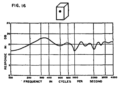
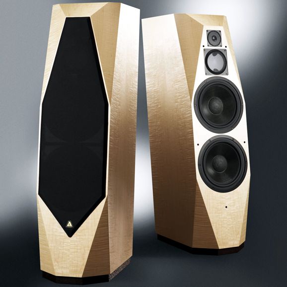
If the driver is mounted off center and the edges receive a wide bevel, things improve immensely. Alas, few bother. Instead, we get limitless rectangular boxes with sharp edges, with a few exceptions from highly esteemed makers such as Avalon Acoustics.
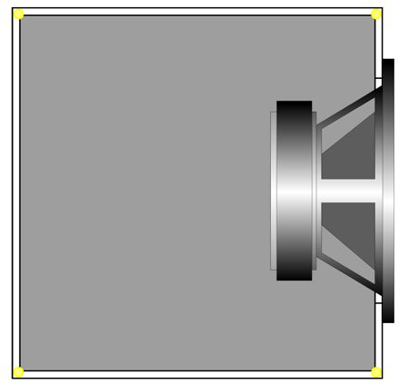
Subwoofers, because of the huge low-frequency wavelengths, are indifferent to the box shape in terms of frequency response ; the biggest subwoofer enclose is still tiny compare to a 20Hz wavelength. But in terms of enclosure rigidity, the cube and the rectangular box are not so hot. Why not? The side panels flex, breathing in and out with the low frequency reproduction. Much like the physics example of how no rope can be pulled taut enough to avoid some sag in the middle due to gravity, no amount of internal bracing can completely prevent a large flat panel from flexing. Now, let's compare the flexing we get from a cylinder with a subwoofer mounted at each flat end. The round side wall intrinsically opposes expanding and contracting, as it lacks the square panels soft center, as all of the cylinder's length must expand and contract equally; in other words, the whole of the cylinder's length is equally stiff. Back in the 1990s in California, a passing fad was to sue the construction companies that built condos for not incorporating sufficient acoustical isolation between units. My first thought was that they had not stuffed the walls with enough fiberglass batting. But the more I thought about it, I realized that this insulation would only limit high frequency transmission, not mid and bass frequencies. I did what I always did: I traveled to the closest university and searched the engineering stacks for books on acoustical isolation in home construction. Dang, the topic was far more complex than I had imagined possible. In short, true, perfect acoustical isolation is as rare as true, perfect sound reproduction—and for many of the same reasons, such as cost and complexity and imperfect materials. For example, if diamonds were as common as aluminum is, then all our woofers, midranges, and tweeters would be made of solid diamond. (I once spoke to a constructor who had worked on a high-end recording studio. He told me that the walls separating the rooms were three feet thick and filled with sand. In addition, they used lead covered sheet-rock panels that are used in X-ray rooms and dentist offices to create a Faraday shielded room.) While reading the literature on acoustical isolation, I saw tables that rated the transparency of various building materials at low frequencies. Surprisingly, the universal speaker cabinet material, MDF (Medium Density Fiberboard i.e. press-board), was next to useless when it came to soundproofing low frequencies. But it wasn't alone, as concrete and sheet-rock were also surprisingly porous. Remember, that at very low frequencies we are not seeking to absorb the sound, but rather to contain the air pressure. It's better to think of tanks of compressed gas rather than foam acoustic panels. Brittle is better than soft. I once built two subwoofer cabinets and lined five of the internal walls with thick felt and then glass window panes and then felt again, with no other acoustic filling material. Because I had two cabinets, I applied this treatment to only one at first so I could hold a shootout. The felt-glass-felt cabinet displayed vastly tighter, more articulate bass. The only downside to the felt-glass-felt was the increased cost, labor, and weight. Ideally, the subwoofer cabinet would be like a large thermos bottle, with one enclosure within another, a vacuum separating both. The great thing about a vacuum is that an 1/8th of inch gap would equal a an 8 inch gap.
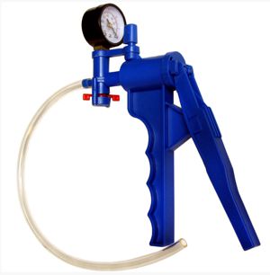
In each of the eight internal corners, we would glue a round plastic pellet to keep the internal enclosure from shifting; I would use the eight of those yellow plastic BBs sold for air-gun use. Think about it: those eight corners would move the least, as they would constitute the stiffest sections of the two cubes. Imagine tuning up your subs with a vacuum pump once a month. Much like those turkeys with doneness pop-up indicator, each subwoofer cabinet could hold a pop-up loss of vacuum plunger.
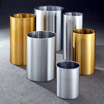
Well, I have seen some lovely brushed aluminum pipes in the form of waste-paper cans in ritzy offices.
Since I am a born hacker, when I spotted these metal cylinders, I wondered what other use they could be put to, such as speaker enclosures. I know what you are thinking: sure the rigid metal in a round shape will prevent bass flexing, but the cylinder is a horrifically bad shape for a bass enclosure, as it acoustically resembles an organ pipe. True enough, as the parallel sides are a big problem in terms of standing waves —but I have a workaround. Let's first look at the speaker drivers themselves, starting with the tweeters. Yes, two tweeters per enclosure.
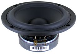
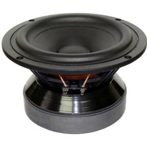
Back in post 451, I detailed the theory behind this arrangement. In short, they provide 360 degree radiation in the horizontal plane. If we place then atop a woofer that fire downward into the speaker enclosure, we get an approximation to an omnidirectional speaker. The woofer should offer an unobstructed opening at its back, such as the SB Acoustics SB17NRX2C35-8.
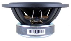
This 6" woofer holds a paper cone and a rubber surround and presents an Fs of 35Hz. Another possible choice is the Tang Band W6-1721.
Note the excellent flaring on the magnet assembly. In addition, Seas makes several woofers with cast frames that offer little obstruction of the back wave.
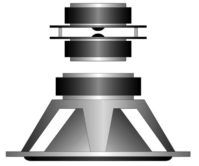
So far, so good. Next we place the drivers in a truncated metal cone, which in turn fits inside a straight metal pipe.
The woofer no longer fires into an organ pipe, as the walls are not parallel, neither on the way down or on the way up and out. This is a transmission-line enclosure. Missing from my drawing is the sound-absorbing material, poly-fill or wool. At the bottom of the enclosure we find a cone that directs the sound around the bend. (We could and should add a complementary corner bevel to reflect the sound up the outer pipe. How do we fabricate the truncated inner cone? My guess is that a metal fabrication firm would take a roll of sheet metal and cut and weld it with one long seam. Possibly, a straight pipe could be expanded at one end and along its length it would receive less and less expanding to the other end, much as wedding rings are expanded . Since we wouldn't see the inner pipe, it need not be attractive. Thus, a straight pipe could receive several long triangular cuts at one end and the remaining segments of the pipe could be pressed together and welded. By the way, my drawing is not to scale. Remember, that with circles to double the area we need only increase the diameter by the square-root of two, i.e. 1.414. Thus, the bottom diameter of the truncated cone in the center should be 1/1.414 as wide as the outer pipe. For example, if the outer pipe diameter is 14.14 inches, the bottom diameter of the truncated cone should be 10 inches. It's top diameter could be 13 inches. I should mention that one great feature of the transmission-line speaker enclosure is that due to its open end doesn't build up the pressure that a sealed enclosure does. In other words, the cylindrical enclosure might only prove slightly better than the old-fashion square box. Thus, we could replace all the pipes and metal with wood. The internal structure would be a truncated pyramid.
Four internal metal braces (one in each corner and covered in thick felt) would hold the top panel in place. The large outer wood panels could receive bracing wood strips. At the very bottom-center, we would place a wood pyramid to reflect the downward waves.
Hybrid Cascodes
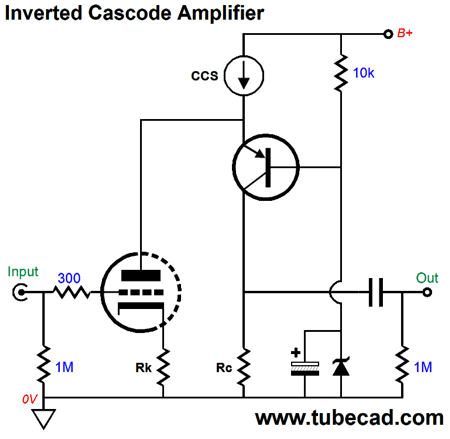
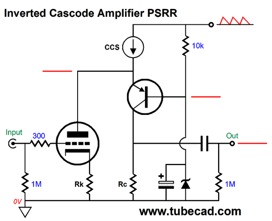
The PNP transistor relays to its collector resistor all the variations in anti-phase current flow that the triode creates in response to the input signal at its grid. If the triode conducts less current, the transistor must conduct more; if the triode draws more, the transistor less. Since the PNP transistor's collector resistor is in the same current path as the transistor, its voltage drop will vary with the transistor's current variation. In short, the cascode arrangement preserves the triode's transconductance.
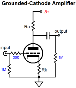
In contrast, in the grounded-cathode amplifier, the triode's plate resistor robs the triode of some of its transconductance. In addition, an unbypassed cathode resistor steals transconductance. Both resistors, however, work to linearize the triode, as both develop degenerative negative feedback. The triode in a cascode topology isn't so lucky, as the bottom triode sees no degenerative feedback at its plate and its cathode resistor is usually shunted by a bypass capacitor, for the goal is usually higher gain. In a grounded-cathode amplifier configuration, the gain can never exceed the triode's amplification factor (mu). In a cascode configuration, however, this limit is removed, as the resulting gain roughly equals the triode's transconductance against the load resistance. In other words, the higher the load resistance, the higher the gain. The inverted cascode is a special case, as the constant-current source makes the power-supply noise invisible to the triode's plate and the transistor's emitter. And all that is needed to shield the transistor's base from the ripple is a large-valued shunting capacitor to ground.
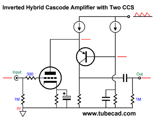
The PNP transistor is effectively a voltage regulator of sorts, which delivers a clean DC voltage at the triode's plate. In fact, we can double up on the constant-current sources, using the second fixed current flow to establish a fixed voltage drop across a resistor to ground, rather than the relatively noisy zener. A capacitor undergoing charging by a constant-current source will ramp up linearly, so the triode can experience a slow ramp up of the B+ voltage. The slighter the current flow and the larger the capacitor value, the slower the ramp up of voltage. Note that the left constant-current source only needs about 10V to operate within. The result is that we can get away with a far lower B+ voltage than is typically used.
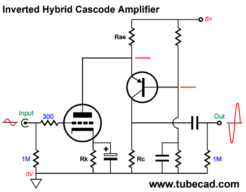
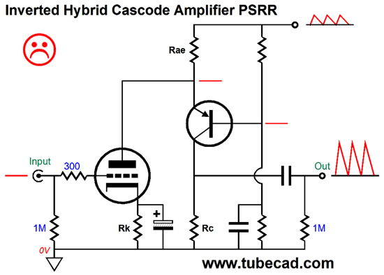
Okay, what if we forgo the use of the constant-current source at the triode's plate? What if we replace that constant-current source with a resistor? One immediate result is that we must increase the B+ voltage. For example, where we could have got away with a relatively low 120Vdc in the previous examples, we must now use something closer to 150Vdc.
The second result is that we lose the shielding of power-supply noise that the constant-current source provided.
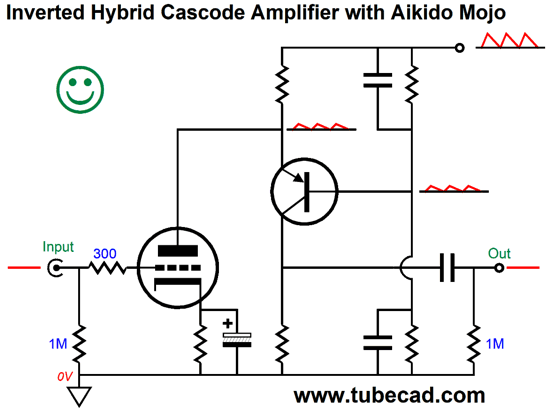
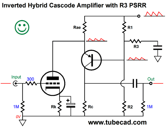
But there is a clever workaround. If we feed the PNP transistor's base an optimal portion of the power-supply noise, then we can achieve a current tie, wherein the triode's rp varying current flow in response to the ripple at its plate is matched by the variations in current flow through the the collector resistor, which results in the collector resistor remaining unperturbed in spite of the B+ voltage noise. This ideal standoff interrelation or balance or equality makes for a simple equation: Ratio/rp = (1 -Ratio)/Rae Where ratio is the amount of power-supply noise and 1 equals the total amount of power-supply noise and rp is the triode's plate resistance, with the assumption that the triode's cathode resistor is bypassed (or that fixed bias is used). Well, after we solve for Ratio, we get this formula: Ratio = 1/(Rae/rp + 1) Instantly, we see that if the triode's plate resistance (rp) equals resistor Rae's value, the ratio would be 0.5, or 50%. In this case, the PNP transistor's base must see half of the power-supply noise riding atop the B+ voltage. How do we achieve this situation? Easy. We bypass the two-resistor voltage divider resistors each with the same valued capacitor, say 10µF.
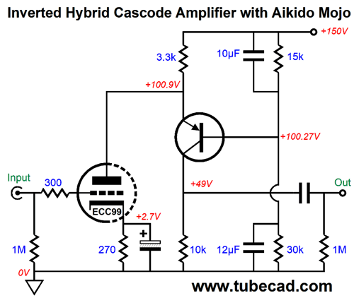
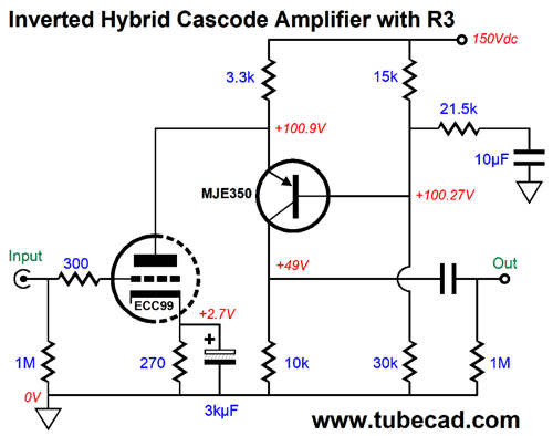
But how are those two resistor values calculated? Their values depend on the B+ voltage, the desired idle current for the triode and for the collector resistor. Remember that the current flow through resistor Rae sets current flow for the entire circuit. For example, if Rae's value is 2k and it sees a 30V voltage drop, the resulting total current flow will be 15mA. How we split up this current between the triode and the collector resistor is up to us. We could give the triode 10mA and the collector resistor would get the remaining 5mA or the triode could get 12mA and the resistor 3mA. Remember that the larger the collector resistor's value, the more gain we realize, but the higher the output impedance will be. (One workaround is to add a cathode follower to the output.) Here is a design example that has received the full treatment, using a single ECC99 triode and two capacitors.
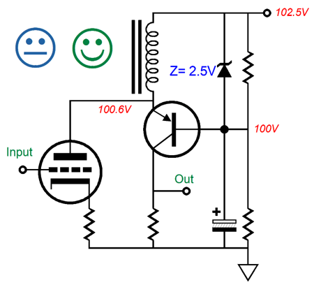
The 10µF and 12µF capacitors define a two-capacitor AC voltage divider, with a 45.45% ratio of the power-supply noise at their output to the transistor's base. Thus, resistor Rae sees 54.54% of the power-supply noise and the triode's rp sees 45.45% of the power-supply noise. In SPICE simulations, the gain came in at 80 and the THD at 1Vpk at 1kHz was 0.1%; in addition, the PSRR was truly fine. In this design example, both the triode's plate resistance and Rae's resistance see the different amounts of power-supply noise and the 10k collector resistor remains shielded from the power-supply noise. What happens if we remove the bottom capacitor that shunts resistor R2? All the power-supply noise would be delivered to the triode's plate, but none of the noise would appear across resistor Rae, so resistor Rae and the PNP transistor would resemble a constant-current source. But as the power-supply noise would induce a varying current flow through the triode, due to its plate resistance, that varying current flow would simply become signal current for the collector resistor and the power-supply noise would become amplified at the output by the ratio between the collector resistor's value over the triode's rp. In this example, 10k/2k, or 5. What if we leave the bottom capacitor in place and remove the capacitor that shunts resistor R1? Now, the triode sees none of the power-supply noise, but resistor Rae does see 100% of it, resulting in the same gain of 5 and five times more power-supply noise will appear at the output than at the B+ voltage. Note that if we get the math wrong, we don't just get some higher portion of the existing power-supply noise, but actual amplification of the noise. In other words, the use of the constant-current source in place of resistor Rae is a good idea. In addition, we face the problem of limited capacitor values and poor capacitance tolerances. (Historically, getting 20% tolerances on capacitor was difficult. Today, with precise film thickness and consistent chemical compositions and highly accurate winding machines with exact tensioning, making 5% tolerance capacitors is a breeze. But since the public is used to 20% tolerances, sly capacitor makers can make 8.5µF capacitors and mark them as being 20% and 10µF, saving themselves 15% in the cost of materials. With electrolytic capacitors, the opposite is often true, as most will actually measure a higher capacitance than the marked value, something like a baker's dozen.) The workaround is not to rely on capacitor values, but on 1% resistors instead.
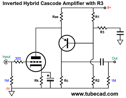
In this circuit, the capacitor's value is no longer critical, as the capacitor merely serves as an AC shunt to ground. Resistor R3 is, in AC terms, in parallel with resistor R2, which then creates two-resistor voltage divider with R1. Two-resistor voltage dividers are among the simplest circuits possible, yet they confuse many. The math is simple enough: Ratio = R2/(R1 + R2) If the two resistor are equal in value, the result is 0.5 or 50%. If R1 is 18k and R2 is 2k, the result is 0.1 or 10%. Okay, simple indeed, but what if we do not know the value of R2? R2 = RatioR1/(1 - Ratio) With the three resistors making up a two-resistor voltage divider, we must find the effective value of R2, which equals the actual value of R2 in parallel with R3. R2' = R2R3/(R2 + R3) We solve for R3 and get: R3 = R2R2'/(Rs - R2') Here is a design example based on the ECC99 triode and one capacitor and three resistors.
The same 45.45% of the power-supply noise appears at the transistor's base.
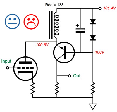
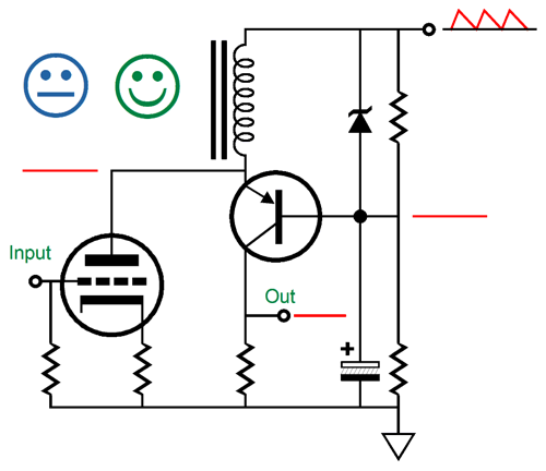
Another possible replacement of the constant-current source is the inductor, but not the SPICE inductor which is an idealized part that presents zero DC resistance and no shunting capacitance, only pure inductance. Real inductors are made from wire and offer a DCR due to the wire's resistance. We could use this resistance to set the idle current flow through the PNP transistor, as the CDR would act like a risistor.
Here the inductor's DC resistance is used as resistor. The two forward biased diodes create voltage reference. The unhappy face is there due to the triode seeing all the power-supply noise.
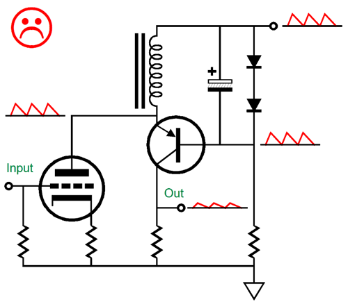
A better place for the shunting capacitor is from ground to the transistor's base.
Now, the triode is shielded from the power-supply noise. The zener is there only as a safety devise to protect the transistor at turn-on, before the shunting capacitor has charged up fully and at turn-off, when the B+ voltage falls to zero, but the electrolytic capacitor is still charged up fully.
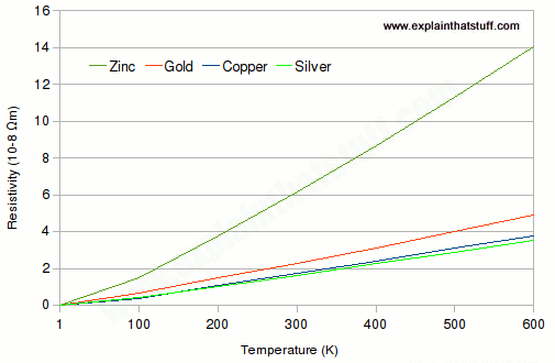
Why does the uncommitted face remain? In general, inductive components and high-voltage combine to create headaches, as the inductor strives to maintain a constant-current flow and varies the voltage drop across its leads to achieve it. In addition, most stuff exhibits a non-constant resistance, as resistance usually varies with temperature. Think about it: resistors are amazing. Unlike a length of copper or silver or gold wire, the resistor's resistance remains fixed in spite of large temperatures variations.
Graph from explainthatstuff.com (Resistors can suffer from voltage-induced non-linearity. This explains why I often show many resistors in series rather than a single resistor in my high-voltage designs, such as electrostatic headphone amplifiers.) Well, the inductor's wire is just copper wire and its resistance is related to the wire's temperature.
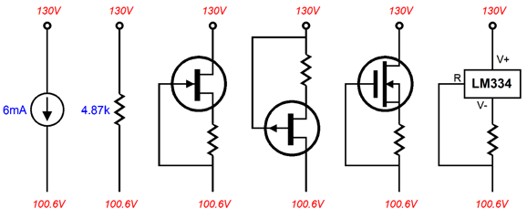
High-Voltage Constant-Current sources Ideally, we would like only two leads on our constant-current source.
Usually, we must use three connections with our constant-current source designs.
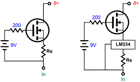
In all three designs shown above, PNP transistors are used, although we could use a P-channel MOSFET in the design at the right. One problem with MOSFETs, however, is their higher capacitance. One problem PNP transistors is their relatively low emitter-to-collector voltage, usually no more than 400Vdc. NPN transistors allow for much higher breakdown voltages, such as the MJW18020G, which is a 250W, 30A, 1kV NPN transistor in the TO-247 package. Another NPN transistor is the HD1750FX made by STMicroelectronics and is rated for 800V and comes in the isolated TO-220 package and cost half as much as the MJW18020G. In comparison, N-channel MOSFETs offer far greater breakdown and far lower prices. For example, the FQU2N100TU made by ON Semiconductor / Fairchild cost about one dollar and offers a 1kV voltage rating. It is only rated for 2.5W and comes in a through-hole TO-251-3 package. I know I complained about the MOSFET's high capacitance, but this MOSFET presents a relatively low 400pF of input capacitance. We could make a high-voltage constant-current source with an N-channel MOSFET and a 9V battery.
The MOSFET's gate does not draw any current, so the shelf-life of the battery equals its use-life in this application. The circuit with the ML334 offers far greater current regulation. Of course, we do the same with a triode.
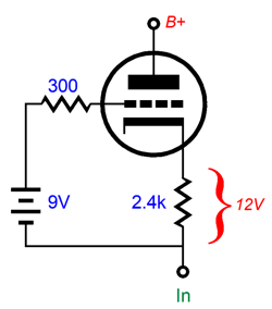
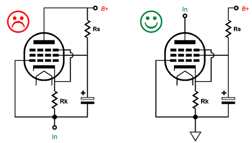
The triode is assumed to be a 6DJ8 type and effectively the 2.4k cathode resistor gets magnified by the triode to equal (mu + 1)Rk + rp, or 84k, worth of resistance. This may not seem to be all that high for an approximation to infinity impedance, but consider that 5mA against 84k equals a voltage drop of 420V. Yet the 6DJ8-based constant-current source can work within a 100V differential. If we replace the cathode resistor with an LM334 constant-current source, then we could use a 3V lithium battery in place of the 9V battery. Surely, some of you are wondering why the triode, being a depletion-mode device that can conduct current with a negative grid voltage, would need a battery. If the triode is a low-mu type and the cathode-to-plate voltage is high enough, then no battery is needed. In contrast, a medium-mu triode and or a low voltage drop requires the additional voltage headroom provided by the battery. For example, a 12AX7, with a cathode-to-plate voltage differential of only 100V and drawing 1mA, will only develop about 0.6V voltage differential between its grid and cathode, not enough to operate an LM334 constant-current source. This same triode with a 3V battery, however, will see a 3.6V differential, easily enough for the solid-state constant-current source. By the way, the shelf-life of a 3V lithium CR2032 coin battery is ten years. (Considering the average age of the average audiophile falls between 50 years to 70 years, you wouldn't have to change all that many batteries in your remaining years ;) In addition, some of you might query the use of the triode, when the pentode offers far greater plate resistance and, thus, more closely approximates a constant-current source all on its own. This is true enough, when the pentode's plate is the constant-current source's output terminal, not its cathode. Why the difference? The screen resistor (Rs) that terminates into the B+ voltage will effectively be in parallel with the pentode, greatly lowering its impedance at its cathode.
In the version on the right, the screen resistor is entirely independent of the plate. Okay, let's move on to solid-state constant-current sources that hold an OpAmp.
This design uses a PNP transistor and an OpAmp and zener diode as a voltage reference. The 300 and 2.7k resistors define a two-resistor voltage divider that reduces the zener's 30V break voltage to a 3V reference voltage for the OpAmp. The only problem with this circuit is that transistor's base draw current, so the current flowing through its collector does not equal the flow through the emitter.
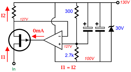
In contrast, a FET's gate does not draw current, so we get a more precise current flow. The new problem is that they do not make high-voltage FETs. The workaround is to cascode the FET with a MOSFET.
In this setup, we could get away with a 30V FET. If you are wondering how the zener and OpAmp get their voltage, here is one possible answer. (The 100V RC filtered voltage is there to attach tot eh PNP transistor in the hybrid inverted cascode circuit.)
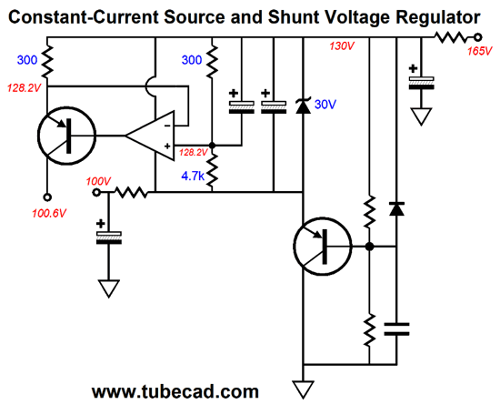
Okay, did your brain just shut off? It looks far worse than it is, however. Let's start with just a simple shunt voltage regulator that uses a PNP transistor.
The zener establishes a fixed 10V refence voltage. The two resistor feeding the transistor base its voltage are feedback resistors that set the output voltage. If we had used an NPN transistor instead and inverted most of the circuit, however, the circuit would seem far simpler.
Resistor R and R2 set the fixed output voltage. If the output voltage climbs too high, the NPN transistor's base will see a portion of that climb and increase its current conduction until the base voltage is brought in line with the fixed zener voltage. In this example, the zener only performs as a voltage reference, nothing more. In the PNP version, I exploited the zener voltage to power the OpAmp. Okay, let's return to a variation on the PNP version.
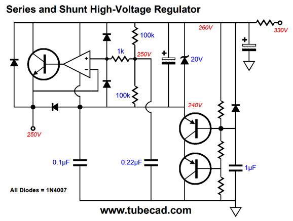
This time I did away with the resistor R2 and used a string of zeners instead. This shunt regulator cannot be used to power OpAmps. (The 3V zener is there to protect eh PNP transistor, as it limits the maximum base-to-emitter voltage.) The following is a high-voltage regulator that I build for a tube-based phono stage almost 40 years ago. At the time, nesting a low-voltage pass transistor in a high-voltage regulator was all the rage.
The OpAmp works under a 20V voltage differential and the NPN transistor never sees more that 20.7 volts from emitter to collector. In fact, if the current flow into the NPN transistor's emitter is trivial, you can eliminate the NPN transistor; I built several versions that used the LM310, which was a unity-gain, non-inverting amplifier made by National Semiconductor. I used the two PNP transistors in cascode for two reasons: at the time high-voltage PNP transistors were not made and I wanted to limit the heat dissipated by each transistor, as they get far hotter in a shunt regulator than in a series regulator. (A shunt regulator can be likened to a class-A output stage; in contrast, a series regulator is closer to a class-AB OPS.)
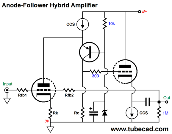
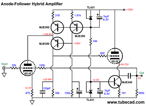
Anode Follower Amplifier Based Inverting Cascode
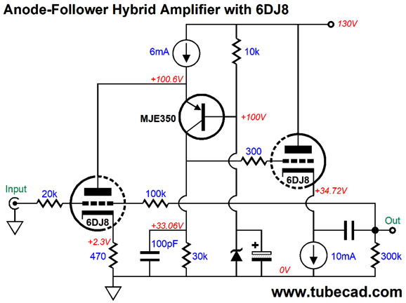
Two constant-current sources are used and the zener establishes the fixed voltage for the PNP transistor's base. Resistors Rfb1 and Rfb2 set the gain by the following formula: Gain = Rfb2/Rfb1 Now, let's look at an actual design example that uses a 6DJ8.
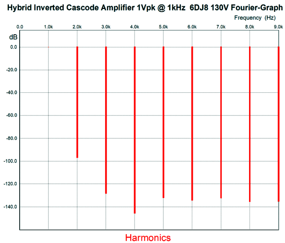
Note the relatively low B+ voltage of only 130Vdc. The 6mA constant-current source's current get divided between the input triode and the 30k collector resistor, with a little less of 5mA going to the triode a little more than 1mA going to the load resistor. The feedback resistors imply a gain of 5, but SPICE simulation revealed a gain of of 4.45 and a PSRR of -29dB. Here is the Fourier graph from SPICE simulation.
The THD is crazy low, as in approaching 0.001%. Okay, since it's easy enough to use constant-current sources in SPICE, how would real constant-current sources be implemented and built?
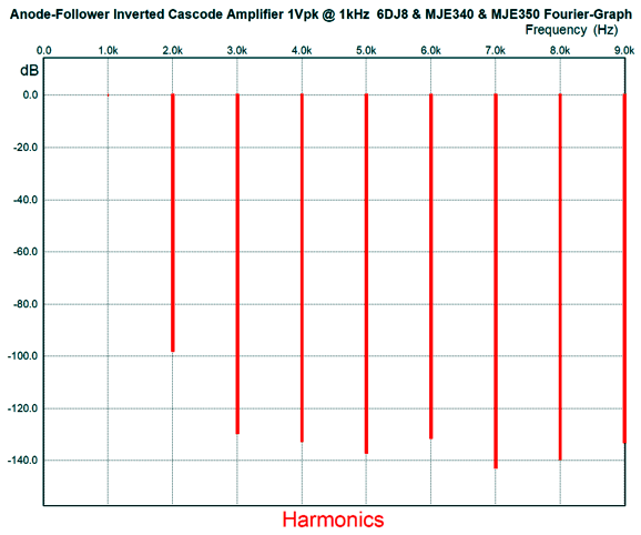
That is how I would do it. Here is the Fourier graph.
Once again, great performance, although not as fine as the version that uses SPICE's ideal constant-current sources, but darn close.
Music Recommendation: Female Singers
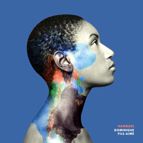
Thanks Larry. Wonderfully recorded and delightful to hear, this is a must listen to album. Fortunately, it is available at Tidal in MQA format. I have only two complaints: the album is only 25 minutes long and I don't know in which genre it fits best. Neo jazz, perhaps, or neo R&B or neo soul? Her voice is the star of every song, with spare instrumental backup. And what a lovely and emotionally compelling voice she has. Tidal offers her third album, Stay Tuned, as well, but not her first album, Sleepy.
Start with Blameless. My own album recommendation is Areni Agbabian's new album on the ECM label, Bloom, which took me by surprise. It, too, like Blameless, eludes easy classification. It might be neo-classical or alternative folk or world jazz. Although Agbabian was born in California, she has not lost connection with her Armenian roots. Classically trained, she can sing anything, from opera to folk music, but her singing is not sterile, quite the contrary. Give the album a listen and you will find her songs continually present in your mind; in other words, haunting. But then I would like her singing, as she reminds me of Susanne Abbuehl, whom I glowingly recommended back in post 424. In short, this is my favorite album of this year so far. Do not just listen to the first track and assume you know what the rest of the album is all about, as you will be wrong.
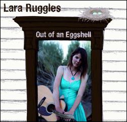
In general, if it's on the ECM label, it's worth hearing. The production values are exemplary. (Have you noticed how ECM has become an audiophile grade label recently?) My second recommendation came to my attention when I bought my Sony Walkman NW-A45 Hi-Res 16GB PAD, which came preloaded with some high-res music files. One of which was a song, Snowflake, by Lara Ruggles, a Boulder Colorado favorite it seems. I was so impressed with her singing that I hunted Tidal for more and I found her album, Cynics & Saints.
Although the production values are not as good as those for the Dominique Fils-Aimé Nameless or the Bloom album—but then few albums are—this album is worth hearing, as Ruggles has a lovely and engaging voice. (At times her voice reminds me of the 1960's singer Melanie, which is a good thing.) She sings in a folk, country, pop style and in spite of her album's title, she sounds young and perky and upbeat. My wish is that she gets discovered by a big label and her next album receives the royal treatment, as I definitely believe she could deliver an amazing album.
Tidal does not offer her other two albums, All the Christmas I Need and Out of an Eggshell, both of which I intend to buy as downloads.
//JRB
User Guides for GlassWare Software Since I am still getting e-mail asking how to buy these GlassWare software programs:
For those of you who still have old computers running Windows XP (32-bit) or any other Windows 32-bit OS, I have setup the download availability of my old old standards: Tube CAD, SE Amp CAD, and Audio Gadgets. The downloads are at the GlassWare-Yahoo store and the price is only $9.95 for each program. http://glass-ware.stores.yahoo.net/adsoffromgla.html So many have asked that I had to do it. WARNING: THESE THREE PROGRAMS WILL NOT RUN UNDER VISTA 64-Bit or WINDOWS 7 & 8 or any other 64-bit OS. One day, I do plan on remaking all of these programs into 64-bit versions, but it will be a huge ordeal, as programming requires vast chunks of noise-free time, something very rare with children running about. Ideally, I would love to come out with versions that run on iPads and Android-OS tablets.
|
Special Thanks to the Special 82
I am truly stunned and appreciative of their support. In addition I want to thank
All of your support makes a big difference. I would love to arrive at the point where creating my posts was my top priority of the day, not something that I have to steal time from other obligations to do. The more support I get, the higher up these posts move up in deserving attention. Only those who have produced a technical white paper or written an article on electronics know just how much time and effort is required to produce one of my posts, as novel circuits must be created, SPICE simulations must be run, schematics must be drawn, and thousands of words must be written. If you have been reading my posts, you know that my lifetime goal is reaching post 1,000. I have 535 more to go. My second goal is to gather 1,000 patrons. I have 918 patrons to go.
The Tube CAD Journal's first companion program, TCJ Filter Design lets you design a filter or crossover (passive, OpAmp or tube) without having to check out thick textbooks from the library and without having to breakout the scientific calculator. This program's goal is to provide a quick and easy display not only of the frequency response, but also of the resistor and capacitor values for a passive and active filters and crossovers. TCJ Filter Design is easy to use, but not lightweight, holding over 60 different filter topologies and up to four filter alignments: While the program's main concern is active filters, solid-state and tube, it also does passive filters. In fact, it can be used to calculate passive crossovers for use with speakers by entering 8 ohms as the terminating resistance. Click on the image below to see the full screen capture.
Tube crossovers are a major part of this program; both buffered and un-buffered tube based filters along with mono-polar and bipolar power supply topologies are covered. Available on a CD-ROM and a downloadable version (4 Megabytes). |
||


| www.tubecad.com Copyright © 1999-2019 GlassWare All Rights Reserved |