| John Broskie's Guide to Tube Circuit Analysis & Design |
21 December 2018 Post 450
PCB Update See post 335 for details on who the lovely lass is in the photo shown above.
Mixed-Bias Fixed bias places a negative voltage on the tube's grid; cathode bias, a cathode resistor or zener or constant-current source between ground and the tube's cathode. Each reduces the tube's current conduction.
The greater the negative grid voltage, the lower the current flow. The higher in value the cathode resistor is, the lower the current flow. Both make the grid lower in voltage relative to the cathode.
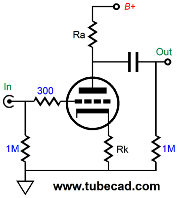
Here is an interesting question: How big in value does a cathode resistor have to be to completely cut off all current flow through the tube? 10k? 100k? 1M? 10M? Well, that was a trick question. In order for the cathode resistor to develop any voltage drop it must see some current flow. In other words, other than infinite resistance, i.e. an open circuit, no cathode resistor value can be high enough to cease all conduction from the tube. Okay, let's say that you want to use a larger valued cathode resistor, but do not want to incur the reduction in idle current that the larger value would prompt. The workaround is to use cathode two resistors in series.
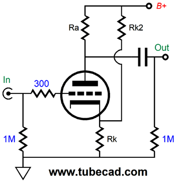
Only the voltage drop across the top cathode resistor, Rk1, is used to set the idle current. In theory, the second cathode resistor, Rk2, might be larger in value than the plate resistor, but it is the top cathode resistor that controls the cathode-to-grid voltage and, thus, the triode's current conduction. The price we must pay, other than increased complexity, is the addition of the input coupling capacitor and the 1M grid resistor. Why would one want a larger-valued cathode resistor? Less gain. Since an unbypassed cathode resistor allows for degenerative negative feedback at the cathode, it reduces the potential gain from the grounded-cathode amplifier.
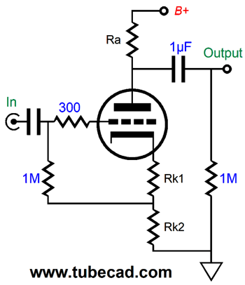
In contrast, we might want to use a lower-valued cathode resistor without having to pay with increased idle current. Once again, we can use two cathode resistors, but only bypass one of them, as shown above.
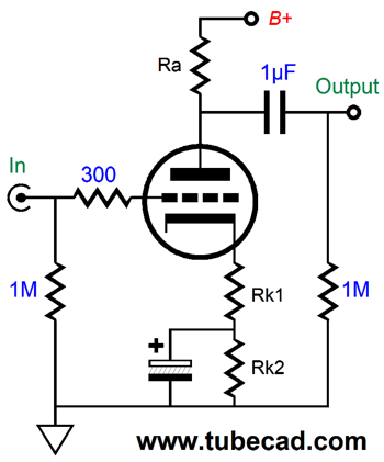
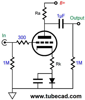
Of course, we could replace the bottom cathode resistor with a zener or an IC voltage reference or a rectifier diode. (And if the cathode voltage is substantial enough, we could use a constant-current source in place of the bottom cathode resistor.) What if you hate bypass capacitors? One workaround is to add a second cathode resistor that is effectively in parallel with the first cathode resistor.
Note how the cathode will experience a higher voltage as a result, as the current flowwing through the triode and the second cathode resistor meet in the cathode that runs into ground, which will make its grid effectively more negative relative to the cathode, which in turn will reduce the idle current flow through the triode. Also note that the second cathode resistor, RK2, terminates into the B+ voltage, not ground. As you might expect, this added resistor will quite large in value. Nonetheless, it is effectively in parallel with the primary cathode resistor, so the parallel resistance must be lower than either resistor's value. Another workaround is to use a constant-current source in place of the second cathode resistor.
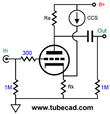
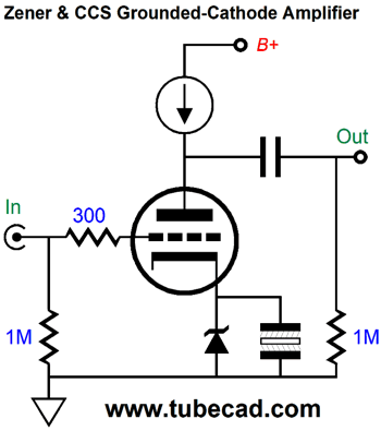
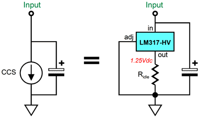
Now, the cathode resistor's resistance remains unaltered. In addition, the constant-current source shields the cathode from the power-supply noise. This is certainly a big feature. We do, however lose an advantage that the second cathode resistor offered; namely, the ability to scale with vary B+ voltages drifts due to wall-socket voltage fluctuations, as the constant-current source presents a fixed current flow, whereas the second cathode resistor's current flow depends on the voltage drop across its leads. Before leaving the topic of constant-current sources, we can obviously use a constant-current source in place of a cathode resistor, but it must be bypassed. (I have gotten more than one email from a reader who didn't use a bypass capacitor across the CCS and wondered why no signal emerged from the output.) We can, however, replace the plate resistor with a constant-current source and use either a cathode resistor or zener to set the cathode voltage.
The odd looking capacitor symbol is for a non-polarized electrolytic capacitor. Before leaving the topic of auto-bias, let's look at related circuit.
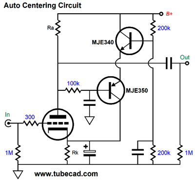
Often we desire to split the B+ voltage at the grounded-cathode amplifier's output. One way to ensure is to use the circuit shown above. The two transistors are configured in a bastode arrangement; they define a differential amplifier. If the plate voltage is greater than half the B+ voltage, the bastode stage decreases its current conduction, which in turn lowers the cathode voltage, effectively making the grid more positive relative to the cathode, prompting an increase in current flow through the tube, which will force the plate voltage down. One feature is that this circuit will auto-scale, as the B+ voltage varies, due to wall-voltage variations. Another auto-biasing technique is the following.
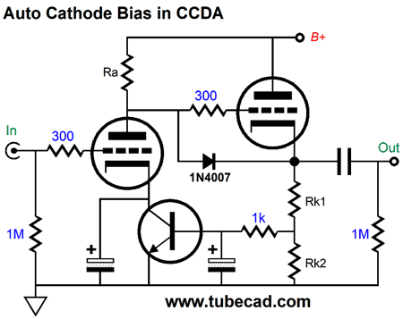
In place of a cathode resistor we see an NPN transistor, whose base monitors the current flow through the cathode-follower's bottom cathode resistor. This technique works best with low-mu tube and high B+ voltages, as the transistor needs to see at least 1 volt of emitter-to-collector voltage. For example, a 12AX7 is a poor choice, but a 6H30 or ECC99 works well. Okay, now that we have all the basics behind us, we now arrive at the mixed-bias technique, wherein we use both grid bias and cathode bias to set the idle current.
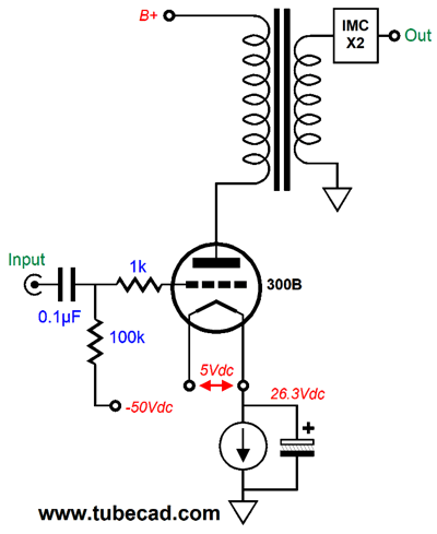
Why bother? At the very least the cathode resistor will allow us to measure the voltage drop across it, which will reveal the current flowing through the tube. This is an important feature in a single-ended amplifier, as there is no plate resistor that could serve the same function. In a line-stage amplifier (or driver stage in a power amplifier), we might want to purposely use a smaller valued unbypassed cathode resistor, so that we might hit some target gain or output impedance. By using both a negative grid bias voltage and a cathode resistor we sidestep the need to use either a diode or zener or a second cathode resistor and the needed bypass capacitor. In a power amplifier that holds low-mu tubes, such as 2A3, 6AS7, 300B tubes, in the output stage, mixed bias works well, as we are able to preserve more of the vital B+ voltage. In other words, we waste less voltage across the cathode resistor. Moreover, we can use a voltage limited constant-current source, because of the lower cathode voltage.
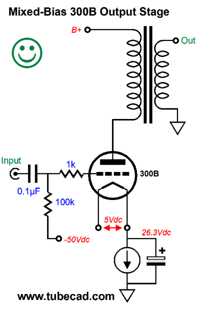
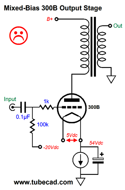
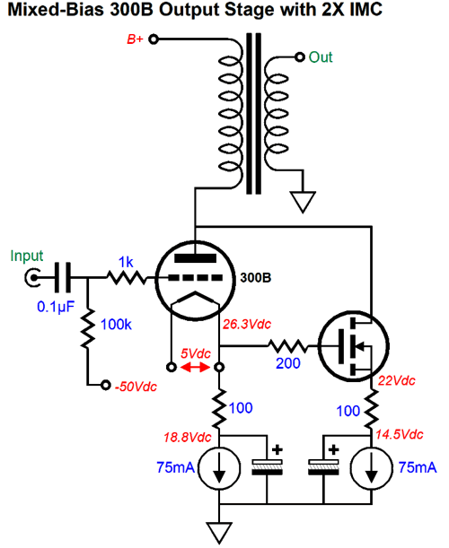
In the above schematic, we see a 300B output tube being auto-biased by the solid-state constant-current source. With only 26V dropped across the constant-current source, we might be able to get away with using a plain LM317, as its voltage limit is 37V. I would, however, opt for the LM317-HV, which is good up to 57V. In fact, I would place a 50V zener across to be safe.
Even with the 57V limit, I would target some much lower cathode voltage.
Obviously, 54V is far too close to the 57V limit. In addition, if the idle current is set to 100mA, then the 54 volts will produce 5.4W of heat. And we do not want to go to the other extreme.
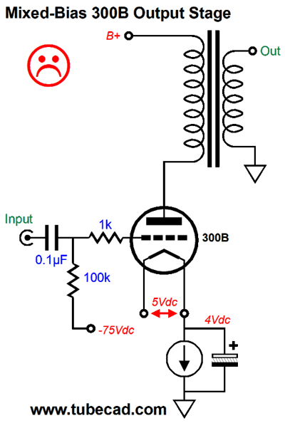
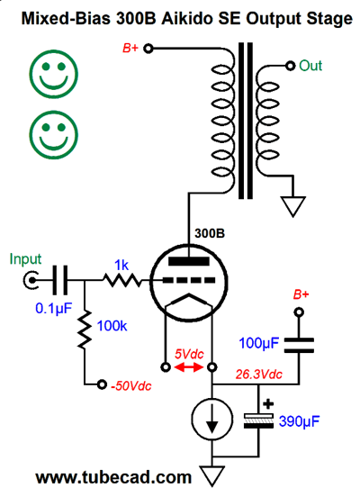
The LM317-HV is not an LDO (low-drop-out) type and 4V is probably touching the lowest useable voltage drop. In other words, 26V was a good middle voltage to aim for. By the way, we can easily upgrade this single-ended output stage by adding one capacitor.
The 100µF capacitor will inject just enough power-supply ripple into the cathode to produce a power-supply-noise null on secondary. This is the Aikido single-ended output stage, which vastly improves the singal-to-noise ratio (i.e. PSRR). See post number 308 for more details.
Creating a Negative Bias Voltage
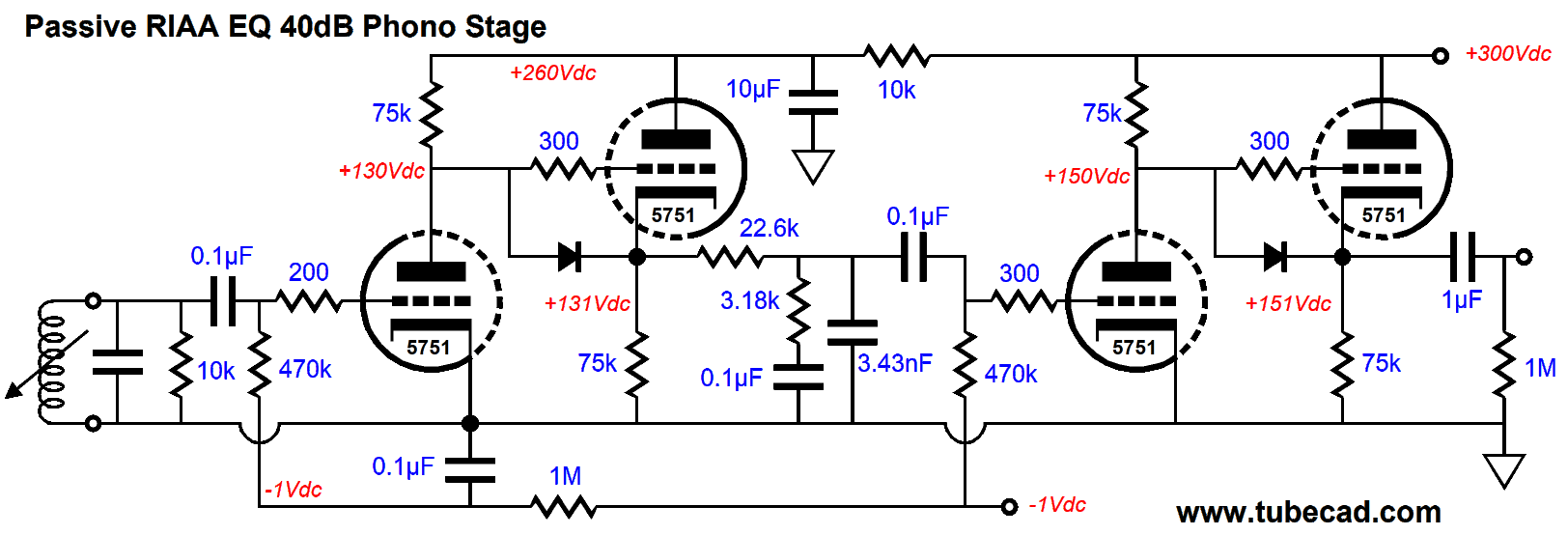
The above circuit will work great with a small signal amplifier, but not with a power amplifier. But before moving on to that workaround, let's look a phono stage I built back in about 1990, which used this very power supply.
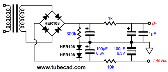
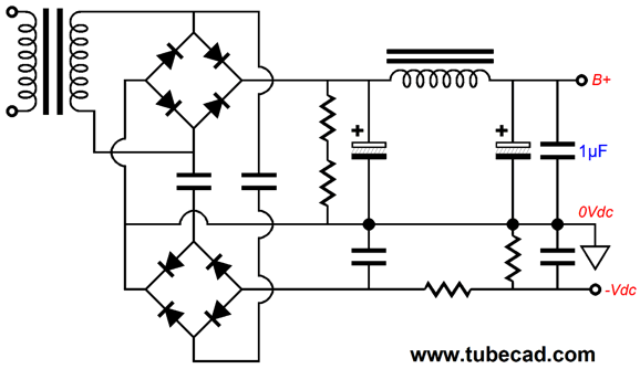
My friend, Tim Eding, had sourced a bunch of low-microphonics 5751 tubes that held an internal tensioning clip that held the mica wafers from rattling, so I had to find a use for them. (Before anyone asks how did it sound, let me say that it sounded great but exhibited too much gain, so I altered the circuit to use two 12AY7/6072 tubes instead.) I wanted to avoid cathode resistors and bypass capacitors, which is way I used negative grid-bias. (I had—on my own—sourced non-inductive 75k wirewound resistors that looked just like bulk-foil types, coming in little square plastic cases.) Note that the phono cartridge sees a 10k load resistance, but a 470k grid resistor is used. With this arrangement, the cartridge could see 100 ohms and the input triode would still see its -1V bias voltage. Also note how the all-important first stage gets an RC filter for its -1Vdc bias voltage. How did I get -1V from -1.46V? Easy. I used a two-resistor voltage divider and bypass capacitor. Okay, now let's us move on to a suitable power supply for a power amplifier. If the power transformer does not hold a center-tap, the following circuit will work.
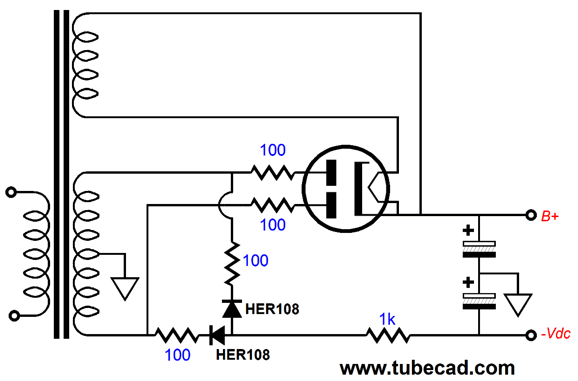
Note that film capacitors are used exclusively on the negative power-supply rail; in addition, they can cheap but high-voltage mylar types. The negative power-supply rail voltage will the negative (the inversion) of the B+ voltage, so high-voltage rectifiers are needed; I like the HER108, which is a 1kV rectifier. If the power transformer does hold a center-tap, the following circuit allows us to create a negative bias voltage.
I left out the post filtering of both the B+ and bias voltages. One danger is that the solid-state rectifiers might see excessive voltage. Remember, in the full-wave center-tap rectifier circuit, the rectifiers must be able to withstand at least twice the raw B+ voltage. For example, a power transformer with a 800Vac CT secondary will not work, as the 1kV rectifiers will see over 1,000Vpk, for 800Vac against 1.414 equals 1,130V. The raw B+ voltage will be half that voltage. I would even be nervous with 1.2kV HEXFred soft-recovery rectifiers.
Single-Ended OPS and IMC
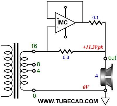
In the circuit above, we see mixed bias and an IMC being used on a single-ended 300B power amplifier's output. In the example below, the impedance ratio is 4:1, so the 4-ohm speaker appears as 16-ohm load to the amplifier.
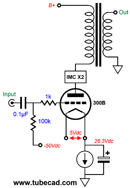
Well, I was wondering if the IMC could not be placed on the primary side of the output transformer, instead of the secondary side.
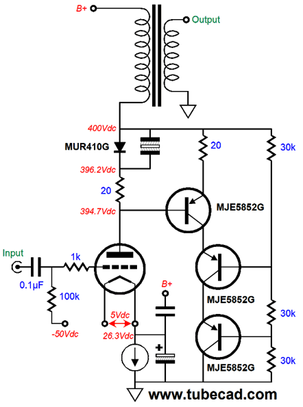
Once again, we would get twice the power output, with not only half the output tubes, but we also could still use all the secondary output taps. In other words, we could use 4-ohm or 8-ohm or 16-ohm speakers without having to fiddle with the IMC. My first thought was to use many PNP transistors in series.
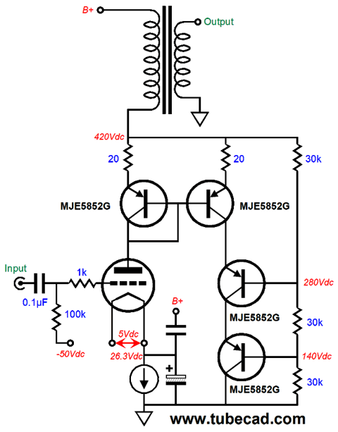
The MJE5852G is a 400V PNP transistor. Three in series would equal 1200 volts. Is this enough? With a B+ voltage of 400V, you would think so, but inductive loads have a way of taking out solid-state devices. Fortunately, compared to the price of a 300B, the transistors are dirt cheap and would, ideally, out last you. If you look at the circuit above, you will notice that the IMC is basically a current mirror, which means we can set up the following.
I ran many SPICE simulations on the above circuit and I was not as pleased as I had hoped I would be. I then tried using two 300B with the same plate load. Pretty much the same results. Apparently, I had gotten too used to super-triode output stages, wherein the triode runs under constant-current, which provokes far less distortion. A current-mirror simply mirrors the current flow. In other words, the circuit did work. While were are at it, let's look an IMC in disguise.
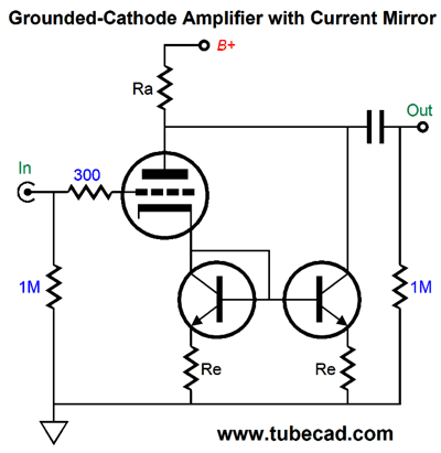
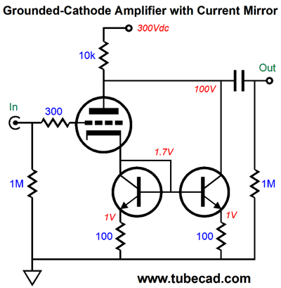
As far as the triode is considered, the plate-load resistor, Ra, appears to be twice as big in value. Here is the same circuit with fleshed out values.
The entire circuit draws 20mA and the 10k plate resistor will dissipates 4W of heat; the triode draws 10mA and dissipates 1W of heat. By the way, the triode effectively sees a cathode resistor value of just 100-ohms. Now, why not apply the same technique to a single-ended power amplifier?
They make high-voltage MOSFETs, as in 4500V, such as the IXTF02N450, but they are not cheap nor that high in wattage or transconductance. On the other hand, a 125W, 2kV MOSFET, the IXYS IXTH1N200P3, can be had for a little over $8 each. I would use at least two 1.2kV MOSFETs in series, as it would at least halve their dissipation and provide greater over-voltage protection.
Okay, why would we bother with this circuit? The answer is simple: 300B tubes are not cheap, particularly NOS types. In addition, we could up the IMC ratio, so that one 300B would be effectively equal to three or four 300Bs. All the flavor of a 300B with four times the power and one fourth the cost. If the 300B idled at 75mA and the IMC's MOSFET string idled at 225mA, bringing the total up to 300mA, and if the load impedance were 800 ohms, the potential power output would be 36W, I² x Rload/2 = Power. The B+ voltage would have to be high enough to sustain 240V of peak voltage swings; in other words a bit over 400Vdc.
Music Recommendation: Susie Arioli's Christmas Dreaming She is never or sloppy or sentimental, nor does she needlessly belt out or strut; instead, she is always measured and confident. In other words, she sings tastefully, with an obvious joy. Her style of singing is definitely in the jazz tradition, which works well with the Christmas songs she selected. Jordan Officer accompanies her on the guitar and his playing is spot on, like her singing his playing is supremely accomplished, but never flashy. Tidal offer this album, and the following two albums from my list of favorites.
//JRB
User Guides for GlassWare Software Since I am still getting e-mail asking how to buy these GlassWare software programs:
For those of you who still have old computers running Windows XP (32-bit) or any other Windows 32-bit OS, I have setup the download availability of my old old standards: Tube CAD, SE Amp CAD, and Audio Gadgets. The downloads are at the GlassWare-Yahoo store and the price is only $9.95 for each program. http://glass-ware.stores.yahoo.net/adsoffromgla.html So many have asked that I had to do it. WARNING: THESE THREE PROGRAMS WILL NOT RUN UNDER VISTA 64-Bit or WINDOWS 7 & 8 or any other 64-bit OS. One day, I do plan on remaking all of these programs into 64-bit versions, but it will be a huge ordeal, as programming requires vast chunks of noise-free time, something very rare with children running about. Ideally, I would love to come out with versions that run on iPads and Android-OS tablets.
|
Special Thanks to the Special 73!
I am truly stunned and appreciative of their support. In addition I want to thank
All of your support makes a big difference. I would love to arrive at the point where creating my posts was my top priority of the day, not something that I have to steal time from other obligations to do. The more support I get, the higher up these posts move up in deserving attention. Only those who have produced a technical white paper or written an article on electronics know just how much time and effort is required to produce one of my posts, as novel circuits must be created, SPICE simulations must be run, schematics must be drawn, and thousands of words must be written. If you have been reading my posts, you know that my lifetime goal is reaching post 1,000. I have 550 more to go. My second goal is to gather 1,000 patrons. I have 927 patrons to go.
The Tube CAD Journal's first companion program, TCJ Filter Design lets you design a filter or crossover (passive, OpAmp or tube) without having to check out thick textbooks from the library and without having to breakout the scientific calculator. This program's goal is to provide a quick and easy display not only of the frequency response, but also of the resistor and capacitor values for a passive and active filters and crossovers. TCJ Filter Design is easy to use, but not lightweight, holding over 60 different filter topologies and up to four filter alignments: While the program's main concern is active filters, solid-state and tube, it also does passive filters. In fact, it can be used to calculate passive crossovers for use with speakers by entering 8 ohms as the terminating resistance. Click on the image below to see the full screen capture.
Tube crossovers are a major part of this program; both buffered and un-buffered tube based filters along with mono-polar and bipolar power supply topologies are covered. Available on a CD-ROM and a downloadable version (4 Megabytes). |
||


| www.tubecad.com Copyright © 1999-2018 GlassWare All Rights Reserved |