| John Broskie's Guide to Tube Circuit Analysis & Design |
09 September 2018 Post 438
More Kick-Butt Design Considerations
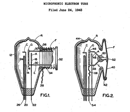
The last essential attribute, that it must handle well, seems the most certain. But many other cars handle well, such as an Army Jeep; in fact, most modern cars handle extremely well, as the art of suspension design drifted away from being an art to become the science of suspension design. (Indeed, take just about any modern car, say a Honda Civic, and transport to fifty years ago and that sensible sedan would certainly be deemed a sports car, supremely so.) The great insight was to realize that a car's suspension was analogous to an electrical resonate circuit comprising resistors, capacitors, and inductors. In other words, you can model your car's suspension in SPICE. Amazingly enough, the topic of suspension brings us back to tube-audio design. Vacuum tubes are delicate mechanical structures encased in glass. And, as a result, are subject to vibrations and they behave like small microphones. In fact, this failing was turned into a feature in the invention of a purposely microphonic triode, whose grid attached to the glass envelope, so the external vibrations could more readily be relayed to the grid and amplified. (US 2,389,935A)
As early as 1926, patents were being issued for anti-microphonic inventions, which usually made use of lead and rubber covers. One patent I remember seeing described a floating assembly to house a triode, wherein the center of gravity was purposely located at the grid position, so that the grid was positioned for the smallest movements. In addition, many patents up until the late 1960s dealt with improving the vacuum tube's internal structure to make the tube less microphonic. Since we have no access to a tube's insides, we must work with its environment. Tubes are mechanically excited by two sources: the sound in the air and the shaking of the chassis that holds the tubes. In an airtight enclosure, as in completely sealed, the tubes would "hear" much less external sound. Wouldn't the tubes get too hot? Maybe, but a lot depends on how many tubes and other heat dissipating devices are enclosed and the size of the enclosure. Remember this, tubes have been used in environments that solid-state devices dare not go, such as near oil-rig drill-bits grinding deep into the ground. In addition, even in an airtight enclosure convection ensures air circulation, as the hot air surrounding the tubes floats up and around the chassis, cooling along its path back to the bottom of the tubes. A much greater concern, in terms of excessive heat, are the resistors. A resistor's power rating is found by suspending it in the air by two test leads. An increasing voltage is applied until the resistor burns out. If this same test is performed with the resistor resting on a table, much less voltage will be needed. Worse still, would be to place the resistor next to other hot resistor resting on the same table (or PCB). The best workaround is to replace RC resistors with inductors, which should only drop a volt or two at most, as they offer a DC resistance far lower than a 10k power resistor.
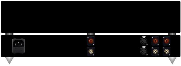
(Long ago, a friend of mine kept having the same problem with his tube phono stage: the plate resistors would burn out. I replaced them with higher wattage resistors and they, too, burned out. This made no sense, as the enclosure held a perforated bottom and top and the resistor dissipation was below the wattage rating. I brought my voltmeter to his house, as I had a hunch that his wall voltage must be running hot. When I saw his system, I realized that I need not measure the wall voltage. I saw the preamp wrapped in a wool blanket. Why? He had found that the blanket greatly reduced tube microphonics. No blanket, no burned-out resistors.) Now, a phono stage based on 12AT7 and 12AX7 and 12AU7 tubes does not dissipate all that much heat, as neither the plate current nor heater current is large. On the other hand, tubes like the 6H30, 5687, and ECC99 in a buffed line-stage amplifier will dissipate much more heat, due to their more robust heaters if nothing else, and should be avoided if possible. In addition, we should locate the power supply in a separate enclosure. Moreover, the sealed enclosure should stand on tall feet to ensure adequate airflow around it. A subtle touch would be to use nylon PCB standoffs and rubber O-rings on both sides of the PCB and nylon screws through the PCB—all of which would soften the vibrations entering the PCB. The enclosure's interior could be lined with the sound-damping material that high-end car-audio installations use, which is a thick metal foil with gooey adhesive bottom. Another possibility would be to use the lead sheeting for sealing off chimneys on rooftops; it, too, comes with an adhesive bottom side. The sealed enclosure should then rest on vibration-quelling feet. Would all this be enough? No. We face a problem few ever mention: the curse of stout interconnects. Thick and massive, some high-end audio interconnects could be used to tow cars. Attach several of these metal snakes to your phono stage or line-stage amplifier and the fancy feet will do little, as the vibrations will pour into the chassis through the rigid interconnects. Is the answer to use only interconnects that are as pliable as cooked spaghetti? No. The massive, stiff cables are so for a reason. But what we can do is to make a separate enclosure to couple to these interconnects. Imagine a line-stage amplifier that held two enclosures, with one sitting atop the other. The top sealed enclosure would hold the line-stage amplifier PCB and tubes, while the bottom enclosure would hold the power supply and all the input and output RCA jacks.
The top sealed enclosure rests on soft plastic shock-mounts that are hollow, so soft wires can be passed from each enclosure to the other. These wire would carry the heater and B+ voltage to the top enclosure along with the input signal. The stepped attenuator would feed line-stage amplifier its signal and the amplifier's output signal would travel down into the bottom enclosure and exit the RCA jacks at its back.
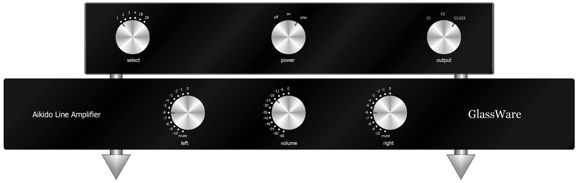
(The assumption behind the above image is that an input transformer would be used in each channel.) Note how the selector switch and power-supply switch are located on the bottom enclosure, along with the power receptacle. The stiff power cord itself can be a conduit to vibration. Spiked feet will firmly hold the bottom enclosure to its resting surface. Of course, we could reverse the assemblies, so the sealed enclosure hangs below the power-supply enclosure. Metal pipes could pass through the hollow shock mounts to fix the power supply enclosure and allow the sealed enclosure below to be suspended. Is this arrangement preferable? I believe it might for two reasons. Placing the power supply enclosure on top allows its heat generation to rise up, without encountering the sealed enclosure. And resting a mass atop a spring always proves more wobbly than suspending the mass from a spring. On the other hand, running wires through threaded pipes is a hassle (and might prove hazardous). In addition, the glue that binds the shock-mount material to the sealed enclosure will have to fight gravity in this arrangement. Moreover, replacing the tubes would prove to be much more of a chore in this setup. In contrast, with the sealed enclosure on top, we could simply remove a top plate to gain access to the tubes.
I am convinced that far too little experimentation takes place in audio. For example, what if it turns out that much of the tube's highly-valued richness is lost in the sealed, vibration-free enclosure? I would bet otherwise, but experimentation would provide the answer. What would such an experiment look like? We could build two identical line-stage amplifiers, with the same sealed and floating top enclosure and power-supply-filled enclosure below. Then we would remove the top plate on one line-stage amplifier and place wood wedges in between its two enclosures, so the shock-mounting was undone. Assemble a group of listeners and and double blind test the sound coming from both setups. Three possible results could obtain: it makes no difference, the non-microphonic setup sounds better, or it sounds worse.
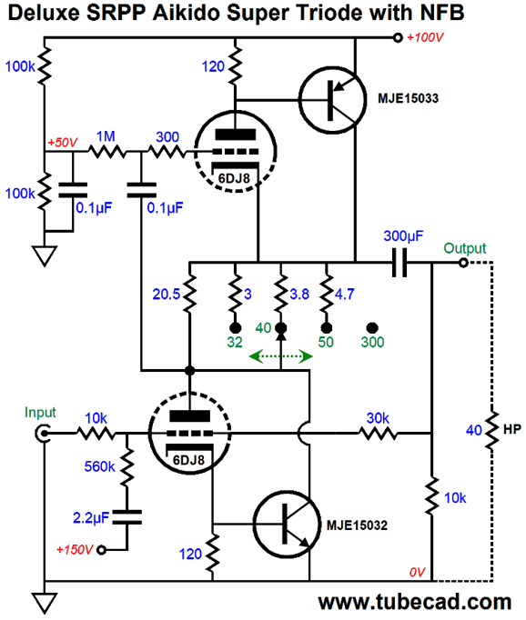
Super-Triode SRPP
After some simulations in SPICE, I saw that the 6DJ8 was a better choice. After fiddling with part values, this was the result.
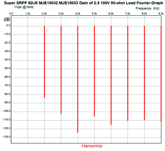
Note the low B+ voltage and single cathode resistor on the bottom triode. The 10k and 30k negative feedback resistors set a gain of 2.5 (+8dB) with a 32-ohm load. I assumed that some solid-state signal source, such as an MP3 player, would drive this headphone amplifier, so its 10k input impedance is not that big of a deal (or rather small of load). In fact, my own experience has been that such signal source benefit greatly from being unloaded, as 10k is 312 times higher in impedance than 32 ohms and the solid-state output stage need only swing 0.1mA to swing 1Vpk. In other words, the signal source's output stage is much more likely to remain within its class-A window of operation. In SPICE simulations, this circuit worked quite well. Here is the SPICE-generated Fourier graph for 1Vpk at 1kHz into 50 ohms.
If we translated the above graph into THD, we would get about 0.01%, which is dang low. One key point to remember is that the SRPP is restricted to strict class-A, push-pull operation; if the bottom triode cuts off altogether, the top triode loses its overlord and input signal source. This circuit idles at about 150mA, so the strict peak potential output current swing is 300mA, which equals 1.44W into 32 ohms. Considering that 100mW is viewed as being powerful by most headphones, the 300mA limit should not prove to be a problem with most headphones. Speaking of headphones, I would certainly think about adding a rotary switch, so that this super SRPP headphone amplifier could be optimized to drive various impedances. The way this would work is we use an Rak resistor value for optimal push-pull operation with the highest headphone impedance, say 300 ohms. In this example, that value was 20.5 ohms. Then we place another resistor in parallel with the 20.5 ohm resistor to bring the value down for the lower headphone impedance.
The PSRR, unlike most SRPP circuits, is exemplary, due to the inclusion of the 560k Aikido resistor to the B+ voltage through the 2.2µF capacitor. The transistors will dissipate 7.5W each, so 2.6°C/W heatsinks will be needed. The heatsink will get hot, but not skin-burning hot. The math is simple. Multiply the transistor dissipation by the heatsink's thermal resistance and you get the heatsink's rise in temperature in Celsius. In this example, we get 19.5°C. This must be added to the ambient temperature to end up with its final temperature, which is usually assumed to be 25°C, but might actually be closer to 35°C, inside a small enclosure filled with tubes and a power supply. Although this design might make some green blacklist, as it would idle at 30W, I would love to hear it. In fact, with an output transformer, we could drive some small loudspeakers, as we might get up to 4W of output. So little time, so many potential projects.
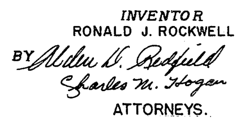
Inventor Ronald J. Rockwell
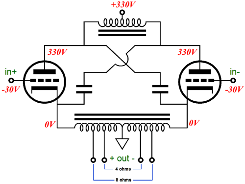
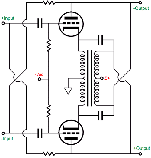
The design shown above, from post 317, shows a center-tapped choke and center-tapped autoformer and two large capacitors that take the place of two floating power supplies. Well, back in 1949, Ronald J. Rockwell applied for a patent for this design: US Patent 2,648,727.
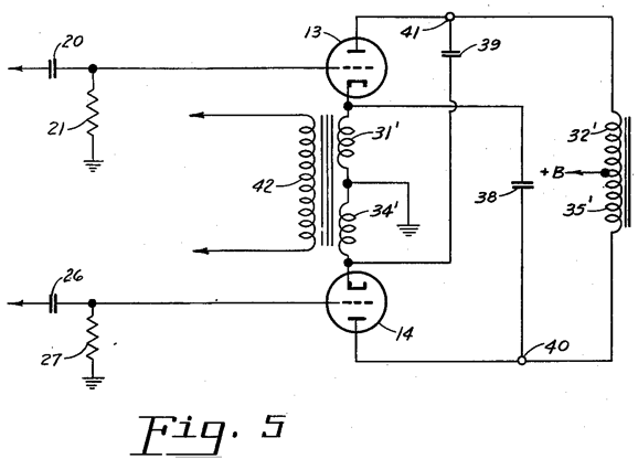
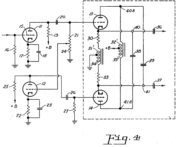
The assumption behind his above patent drawing is that the output transformer's primary would present enough DCR to cathode bias the output tubes. The circlotron output stage offers a gain equal to twice that of a comparable cathode follower, which is always less than unity, so some value close to 2 is the result. In other words, this variation on the circlotron will require big input signal voltage swings. Here is how Mr. Rockwell planned on proving them.
This time two center-tapped chokes are used in the second stage, along with the two large-valued capacitors. In other words, this driver stage is also a circlotron design. The input stage provides gain and phase splitting of the unbalanced input signal. Mr. Rockwell also showed how a 1:1 audio transformer could be used in place of two center-tapped chokes.
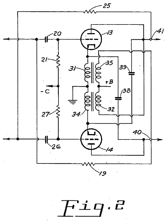
Like most patent schematics, it looks more complicated than it is. I will redraw it.
Maybe a little better, but this topology is hard to see at once. Note that the two large-valued capacitors cross-couple output triode cathodes and plates. They act as floating power supplies, in terms of AC signals. The two resistors attaching to the the two plate look as if they are there to provide some positive feedback to the driver stage. (If I were willing to wade through the patent mumbo jumbo, I would know for certain.) I found three audio-related patents by Mr. Rockwell, the other two being US 2,763,732 (1953) and US 3,324,407. This last patent holds the following schematic.
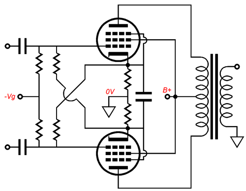
No circlotron action going on here. Instead, we see the garter-belt biasing technique. I have redrawn the biasing portion of the schematic.
Notice how both cathode and fixed bias are used and how the two cathode cross-couple to the other pentode's grids. Also note how a single capacitor bridges both cathodes. If you look back to the original schematic, you will see two negative-feedback loops in play and what looks like the possible introduction of some Aikido mojo through resistors, 57 and 60 and capacitors 56 and 59.
Music Recommendation: Joep Beving
Tidal only offer the two albums shown above. (Well, as far as I can tell this is so. With Tidal, one can never be too sure.) The missing album is Conatus.
//JRB
User Guides for GlassWare Software Since I am still getting e-mail asking how to buy these GlassWare software programs:
For those of you who still have old computers running Windows XP (32-bit) or any other Windows 32-bit OS, I have setup the download availability of my old old standards: Tube CAD, SE Amp CAD, and Audio Gadgets. The downloads are at the GlassWare-Yahoo store and the price is only $9.95 for each program. http://glass-ware.stores.yahoo.net/adsoffromgla.html So many have asked that I had to do it. WARNING: THESE THREE PROGRAMS WILL NOT RUN UNDER VISTA 64-Bit or WINDOWS 7 & 8 or any other 64-bit OS. One day, I do plan on remaking all of these programs into 64-bit versions, but it will be a huge ordeal, as programming requires vast chunks of noise-free time, something very rare with children running about. Ideally, I would love to come out with versions that run on iPads and Android-OS tablets.
//JRB |
Special Thanks to the Special 67!
I am truly stunned and appreciative of their support. In addition I want to thank
All of your support makes a big difference. I would love to arrive at the point where creating my posts was my top priority of the day, not something that I have to steal time from other obligations to do. The more support I get, the higher up these posts move up in deserving attention. Only those who have produced a technical white paper or written an article on electronics know just how much time and effort is required to produce one of my posts, as novel circuits must be created, SPICE simulations must be run, schematics must be drawn, and thousands of words must be written. If you have been reading my posts, you know that my lifetime goal is reaching post 1,000. I have 568 more to go. My second goal is to gather 1,000 patrons. I have 934 patrons to go. Help me get there.
The Tube CAD Journal's first companion program, TCJ Filter Design lets you design a filter or crossover (passive, OpAmp or tube) without having to check out thick textbooks from the library and without having to breakout the scientific calculator. This program's goal is to provide a quick and easy display not only of the frequency response, but also of the resistor and capacitor values for a passive and active filters and crossovers. TCJ Filter Design is easy to use, but not lightweight, holding over 60 different filter topologies and up to four filter alignments: While the program's main concern is active filters, solid-state and tube, it also does passive filters. In fact, it can be used to calculate passive crossovers for use with speakers by entering 8 ohms as the terminating resistance. Click on the image below to see the full screen capture.
Tube crossovers are a major part of this program; both buffered and un-buffered tube based filters along with mono-polar and bipolar power supply topologies are covered. Available on a CD-ROM and a downloadable version (4 Megabytes). |
||


| www.tubecad.com Copyright © 1999-2018 GlassWare All Rights Reserved |