| John Broskie's Guide to Tube Circuit Analysis & Design |
23 July 2018 Post 432 I am back and I have been this last week. I would like to say that I am rested and ready to go, but that would be a lie. When a undertaker goes on vacation, those who died in his absence, were buried in his absence. When the baker goes on vacation, he is not required to bake the bread he failed to bake while gone. With the self-employed, on the other hand, all the work you didn't do is still there waiting for your return. Thus, I have been playing catch-up all this week. So much so that I haven't even had a chance to give the new Aikido octal All-in-One some further listening, let alone finish writing a user guide for it. This doesn't mean that I didn't have a good time, far from it. But at all times, the specter of work not done loomed about me. I did, however, manage to come up with a clever sentence, even if I was the only who thought so. I said it next to the swimming pool in response to my relatives asking where my teenage son was. "Transfixed remain the eyes that gaze upon pixels." To utter such a sentence spontaneously, without benevolence aforethought, but in remembrance of Shakespeare's line from his play King Henry IV, "Uneasy lies the head that wears a crown,” is enough to make me happy for days.
Simple Designs
In the example of my "naked" single-ended amplifier, however, I had simply passed on to the line-stage amplifier the chore of deliver sufficient output voltage swing to drive the naked amplifier to full output, as it required tens of volts, not one volt. And in the example of the phono preamp, the missing signal gain the single triode cannot provide is delivered by the two signal transformers. In other words, super simple often requires shifting cost or complexity elsewhere, much like the driver of an electric car who naively believes that his driving creates no pollution, while he ignores the pollution created by power station that charged his car's batteries, which becomes magnified when all the losses entailed in the power transmission and all the inefficiencies in charging his car's batteries are taken into account. (If a battery gets hot during charging, and batteries do get plenty hot, then power is being wasted.) Buddhist monks in Thailand do not shop for or cook their meals; instead, empty bowl in hand, they beg each morning and are fed by others, others who do shop and cook food.
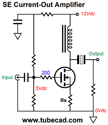
In contrast, a single-MOSFET or single-transistor power amplifier can be imagined. The following design is a current-output design uses a single active device.
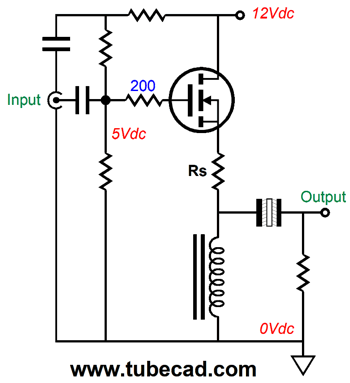
The inductor takes the pace of an elaborate constant-current source and allows us to use half the B+ voltage we would have to use in the constant-current source version. If we want voltage-output, not current-output, then we must rearrange the topology, creating a source follower power buffer.
Much like my "naked" efforts, this power buffer will require a hot input signal, which will once again pass on needed functionality to the line-stage amplifier. In contrast, a single-triode line-stage amplifier seems certainly possible; and, indeed, it is.
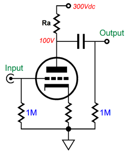
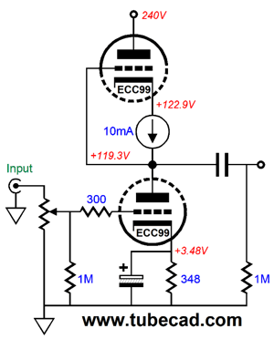
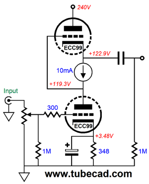
The grounded-cathode amplifier shown above required only one coupling capacitor and four resistors and volume potentiometer. Possibly this is all that you need in your system. But this simple line-stage amplifier assumes that a low output impedance is not require and that the power supply will be noise-free. Making a noise-free high-voltage power supply is easy but expensive, if you go the big choke route; and complex and relatively cheap, if you go the regulator route. On the other hand, if we replace the grounded-cathode amplifier's plate resistor with an inductor or constant-current source, we can both run a lower B+ voltage and worry less about power-supply noise. On the other hand, we can place a low-voltage constant-current source in between a triode's cathode and its grid, as shown below.
The B+ voltage is still a high 240V, but the PSRR is amazingly good. The constant-current source could a simple LM334. This leaves the potential problem of a high output impedance. Bypassing the cathode resistor will bring the output impedance down to the triode's plate resistance. What if this is not enough? We could rearrange the circuit shown above into a mu follower, which would dramatically lower the output impedance, but at the cost of much worse PSRR.
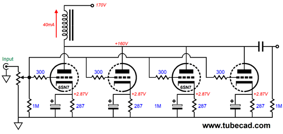
We could use more triodes in parallel, which would certainly run counter to a one-triode or one tube rule, but would still conform to the same simple grounded-cathode amplifier scheme, albeit with several triodes in parallel. Imagine four 6SN7 triodes in parallel, which would entail two 6SN7 tubes per channel. The result with bypassed cathode resistors would be an effective plate resistance of about 2k, not the 8k that one 6SN7 presents. The inductor loading both shields the plates from noise and allows us to get away with a low 170V B+ voltage.
I used to be known for having a lead foot when it came to idle current. Where a friend would run his 6SN7 with 2mA of idle current, I would run 10mA. Why? The higher current flow lifted the 6SN7 out of the sloppy bottom of its plate curves. For example, at a plate voltage of 160V, the 10mA of idle current produces about twice the transconductance and half the plate resistance that the same 6SN7 deliver at 2mA of current flow. In other words, the higher idle current gives us effectively a twice as good triode, but at the cost of a shorter life span. Moreover, I believe high current delivery is far more important than low output impedance in a line amplifier, as few power amplifiers present an input impedance below 20k, but long lengths of high-end interconnect can present a heavy capacitance. In order to charge and discharge capacitance at a fast rate requires current, as slew-rate times capacitance equals current: I = Slewrate x C If we solve for slewrate, we get Slewrate = I/C Slew rate can also be found from this formula: Slewrate = 2piFVpk / 1,000,000 where pi equals 3.14159 and F equals the highest frequency you wish to reproduce and Vpk is the highest peak voltage swing. By placing four triodes in parallel we lowered the output impedance and increased the idle current to a healthy 40mA, which can certainly burn through a lot of capacitance, furthering high-frequency response. But at the same, we have increased the input capacitance by fourfold, which can limit the high-frequency bandwidth. Do not forget about the dreaded Miller-effect capacitance, where the static grid-to-plate capacitance become magnified by the triode's gain at its plate. A single 6SN7 triode's grid-to-plate capacitance is close to 4pF, so we get 16pF for four in parallel and with a gain of 9, we end up with 160pF of input capacitance. Is that a problem? It is if you use a 100k volume potentiometer, as it maximum output output impedance is at -6dB of attenuation, where it equals 25k, which will produce a -3dB high-frequency cutoff frequency of 40kHz. Wait a minute, John, I do not own a pet bat and my dog doesn't share my musical tastes, besides CDs stop at 22kHz, so who cares? Understand that the droop gets a good head-start below 40kHz. For example, at 20kHz, the response will be down close to -1dB. Now let say that your tube-based power amplifier only goes out to 40kHz as well; this cascade of low-pass filters means a droop of almost -2dB at 20kHz. And most tweeters are already a few dB down at 20kHz, so we can expect a sagging high-frequency extension. In other words, it's safer to have a bit wider bandwidth. Fortunately, there is a workaround; In fact, a subtle workaround.
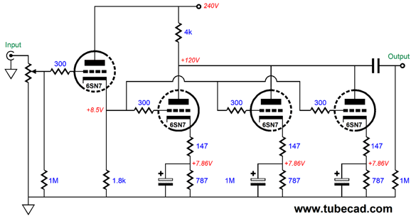
In the schematic shown above, the input cathode follower shields the volume potentiometer from the three triodes high input capacitance. This arrangement is somewhat similar to a cathode-coupled amplifier. Moreover, the cathode follower leaks some B+ voltage power-supply noise into its cathode output, so the three triodes in parallel see that small sampling of power-supply noise and amplify it—and invert it—at their combined plates. I said it was subtle, so bear with me. If we choose the right un-bypassed cathode resistor value, we end up creating a stellar PSRR figure, as the inverted and amplified power-supply noise nulls the actual power-supply noise. In other words:
Where do you buy a power 4k resistor? You don't; instead, you place three 12k or four 16k resistors in parallel If two 6SN7 tubes per channel is too much, just leave one out and use two triodes per channel, with a 12k plate resistor.
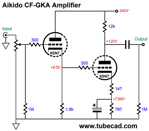
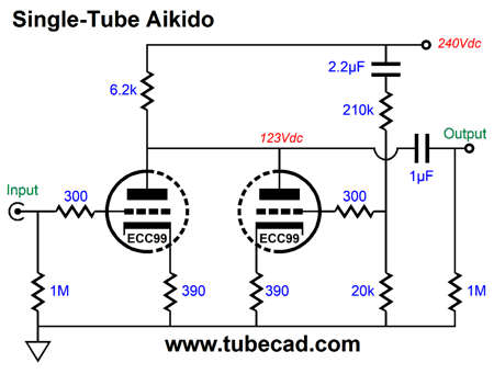
Or we could get extra fancy and give the cathode follower and grounded-cathode amplifiers a constant-current source load, but I would certainly try this simple version first. Another simple line-stage amplifier that partook of Aikido mojo could be made from just two triodes, i.e. one dual-triode tube per channel.
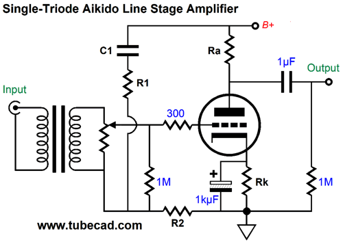
The triode on the left sees the input signal at its grid and does all the signal amplification. The triode on the right enhances the PSRR, as its grid sees a portion of the power-supply noise and amplifies and inverts it at its plate. Once again, we get huge improvement in PSRR. If we bypass the cathode resistors, we will have to find a new values for the two-resistor voltage divider. Okay, how about just one triode and Aikido mojo, is that possible? It is, but it will require an input isolation transformer. The trick is to couple the transformer's secondary to a two-resistor voltage divider, so that an optimal amount of power-supply noise can be superimposed onto the triode's input signal, which will lead to the noise's null at the output, even when the volume potentiometer is fully off.
Since we are using a bypass capacitor on the cathode resistor, we can eliminate the capacitor at the two-resistor voltage divider (R1 & R2).
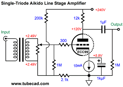
Note that the cathode resistor has been replaced by the constant-current source; of course, we could just use a 590-ohm resistor in place of the constant-current source. Also note the DC offset present at the triode's grid. Further note that the signal transformer's secondary does not see any DC current flow. I have shown this technique before in phono preamps and in Chromecast-Audio applications, where a tube circuit follows the puck.
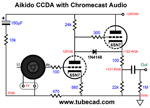
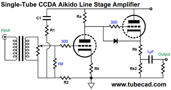
Thus, a slightly better, but still plenty simple, circuit would be to use a constant-current-draw amplifier (CCDA) stage, as it unloads the power supply (in AC terms, not DC terms) and it offers a low output impedance.
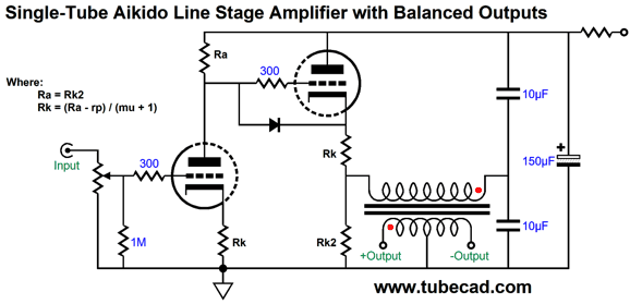
Note that the input signal transformer allows either unbalanced (RCA jack) or balanced (XLR jack) input signal. In addition, it keeps the signal source's output truly separate, as the primaries only attach to ground in the signal source, not at the stereo line-stage amplifier input. in other words, the input transformer is a wonderful way to sidestep ground-loops or other hum headaches. What if we want the option of balanced outputs? No problem, just add an output transformer, which can also hold a 1:1 winding ratio.
Note how the Aikido mojo obtains at the output transformer, not at the input transformer. The two 10µF power-supply capacitors define a two-capacitor voltage divider, so 50% of the power-supply noise will appear at the connection between capacitors. The same 50% of the power-supply noise will appear at the cathode follower's output, if we are careful about part selection values. Since the same amount of power-supply noise appears at the output transformer's primary, none of the noise appears across the secondary, as the transformer is an intrinsically differential device that can only pass AC difference and ignores common-mode signal.
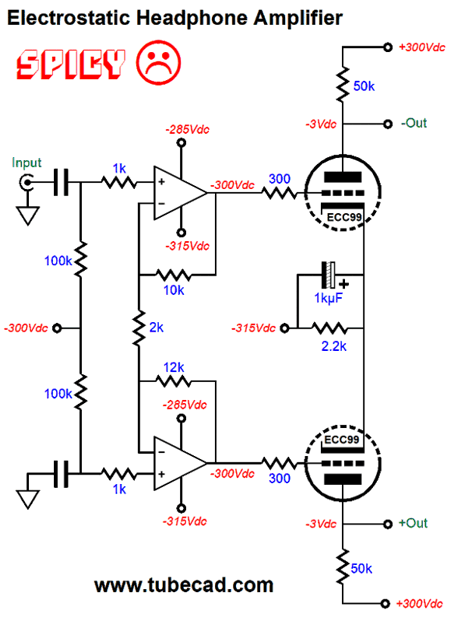
Hybrid Electrostatic Headphone Amplifier
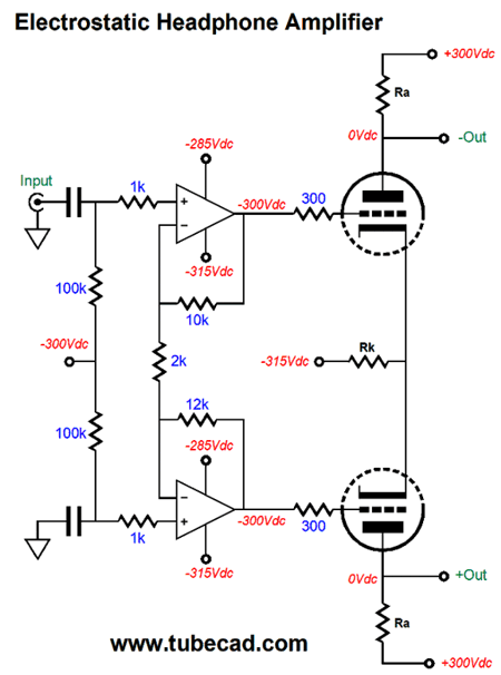
What you see above is the basic idea without the modification. The top OpAmp sees the input signal and the bottom OpAmp sees the ground. This arrangement is important, but could easily be hidden in SPICE simulations. In SPICE, the power supplies (the voltage sources) are perfect, just the opposite of reality. Real power supplies are not a noise-free AC equivalent of ground; instead, they present output resistance and inductance and ripple. One thing we can safely assume is that a B+ voltage of 300Vdc is likely to hold three times as much ripple as a 100V power supply. If ripple is 1% of the power supply voltage, then a 300V power supply will present 3V of ripple. In other words, we must take the potential problem of ripple in our design.
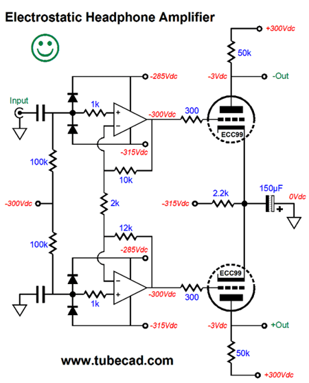
The unhappy face is due to the shared cathode resistor being bypassed by a large-valued capacitor, which will couple all the negative power-supply rail ripple to the two cathodes, which in turn will treat the ripple as a signal to be amplified. If we leave the bypass capacitor out of the circuit, we still get amplified ripple, just a less of it. Since the electrostatic headphone is itself an intrinsically differential device, does the amplified ripple matter? It can. Here is how: the ECC99 will amplify 1Vpk of ripple by roughly its mu, as the plate load resistor is so much larger than its own plate resistance, so 22Vpk will appear at the plates, which will rob potential useful output voltage swing, as the amplifier will clip 11V sooner than it would other wise; In addition, the ripple can intermodulate with the actual music signal, needlessly increase the THD. The easiest workaround is to bypass the shared cathode resistor in the following way.
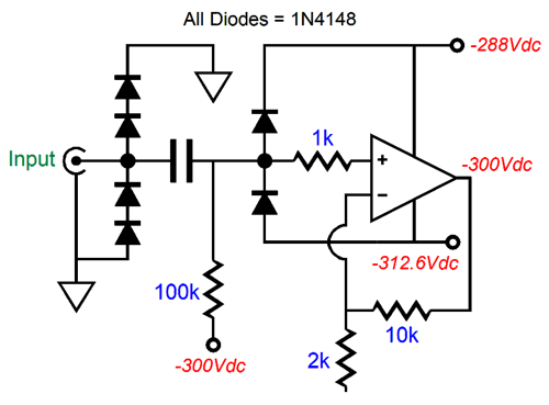
Now, the coupled cathodes are locked in AC terms to the ground. In SPICE simulation with a 150µF capacitor, 60mVpk appears at the plate, 10mV resulting from the negative power-supply rail and 50mV from the positive power-supply rail. And the 10mV must be divided by 22 to find the amount of ripple present at the coupled cathodes. Yes, I did sneak in some extra, but essential parts: the four diodes. The two OpAmps sit at -300V, but their inputs are capacitor coupled to ground potential, i.e. 0V. These coupling capacitors must charge up to 300V, which will take some time, during which the OpAmps can be damaged. But wit the diodes in place, the maximum, input voltage the OpAmps can see is +/-15V,relative to their power-supply rail voltages. In fact, we could add some more protection diodes at the input.
Now, both the signal source and the OpAmps are protected at turn on while the input coupling capacitor charges up to 300V. Another workaround would be to forgo the bypass capacitor altogether and replace the 2.2k shared cathode resistor with a 12mA constant-current source. The only thing that I do not like about this workaround is that if the wall voltage varies, the constant-current source will not auto-correct to put the two plates at ground potential, whereas the cathode resistor,bypassed or not, would do so. Another workaround would be to cross-couple the OpAmp outputs.
The odd looking capacitor symbol is for an non-polarized electrolytic capacitor. These capacitor cross-couple the OpAmp outputs so both the triode's grid and cathode are driven, resulting in twice the gain from the triode. In addition, the capacitors shield the cathodes from the negative power-supply rail ripple. Moreover, as we retained the cathode resistors, the outputs that connects to the stators will still tend to center near ground potential, even if the wall voltage varies. If this is not deemed a worth feature, we can think about the following version, which uses PNP transistors to drive the cathodes, unloading the OpAmps.
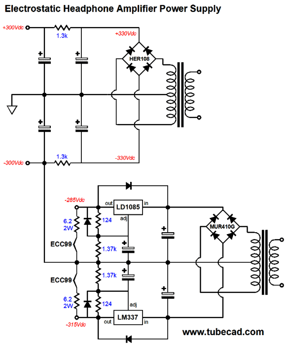
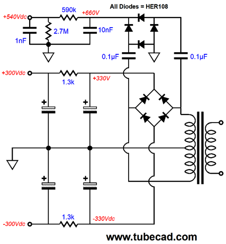
Note the addition of internal coupling capacitors and grid resistors. In addition, note the two 10k resistors that attach to the cathodes and terminate into the -288Vdc rail voltage. Why are they there? At startup, when the tubes are cold and not conducting, these resistors will complete a current path for the PNP transistors. While we are at it, note the effectively +12V and -12.6V power-supply rail voltages for the OpAmps. Due to the cross-coupling from the OpAmps outputs, the OpAmps do not need to swing as much voltage to establish full output from the triodes, so we do not need +/-15V. But why -12.6V rather than -12V? That was the voltage that in SPICE simulation yielded the centering of the triode plate voltages near ground potential. I show this circuit just to show what is possible, but I would build the version with the cross-coupled non-polarized capacitors instead. In fact, if enough readers were to twist my arm, I might make a PCB for that version. No matter which variation we choose, we will need a power supply for this electrostatic headphone amplifier. The following power supply uses two power transformers, a 480Vct and a 28Vct type.
Note how the two low-voltage regulators and their power supply piggyback on the bipolar high-voltage power supply. Also note how the heaters for both channels find their power source here. The 6.2-ohm power resistors drop the 15V down to 12.6V. The two 1.3k power resistor are part of the RC filtering. What about the electrostatic headphone's bias voltage? If electret headphones are used, you won't one. Adding the bias voltage is no big deal, however, as the schematic below shows. Missing from the schematic is the 20M resistors that attach to the diaphragm.
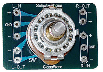
Actually, now that I look at the heater portion of the complete schematic, I could easily be convinced to have both heater elements powered by the positive regulator. Why? Such a move would greatly unload the negative regulator and most OpAmps have a much poorer PSRR figure from their negative power-supply pin than from their positive power-supply pin. Speaking of OpAmps, which would I use in this circuit? I would certainly try the OPA2107, but other dual OpAmps are worth trying. One item that I would deem essential is one of my GlassWare Select-Phase switches.
Located at ES amplifier outputs, this stereo switch would not only let us choose the phase, but park the output at ground at turn-off. Then, when we turn on the amplifier, the ECC99 tubes see 300V less voltage on their plates.
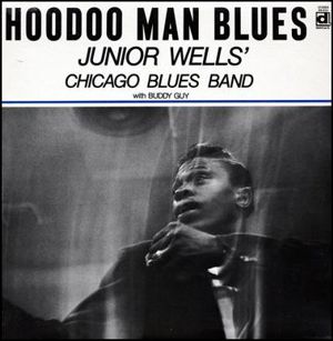
Music Recommendation: Junior Wells and Buddy Guy
The whole album is worth listening to over and over, but my favorite track was "In the Wee Wee Hours." Fortunately, Tidal does offer this album, but not under either Junior Wells or under Buddy Guy, strangely, insanely enough. You can find it, however, by searching for the title, Hoodoo Man Blues. I began this music recommendation practice by extolling the sound and artistry of Buddy Guy's album, Blues Singer, back in post number 203.
Tidal does offer this album and twenty others by Buddy Guy. Tidal recently added his 2018 album, The Blues Is Alive And Well, where he is joined by James Bay, Jeff Beck, Mick Jagger, and Keith Richards. (When I lived in San Francisco almost forty years ago, I would often frequent the blues joints in North Beach district. One night I arrived at my favorite club and the owner told me that I should have been there two nights before, as Mick and gang had arrived to listen to performances.)
I highly recommend it. I can only pray that I have half his mojo when I am 81. While you are at Tidal, be sure to give his album, Sweat Tea, a listen.
//JRB
User Guides for GlassWare Software Since I am still getting e-mail asking how to buy these GlassWare software programs:
For those of you who still have old computers running Windows XP (32-bit) or any other Windows 32-bit OS, I have setup the download availability of my old old standards: Tube CAD, SE Amp CAD, and Audio Gadgets. The downloads are at the GlassWare-Yahoo store and the price is only $9.95 for each program. http://glass-ware.stores.yahoo.net/adsoffromgla.html So many have asked that I had to do it. WARNING: THESE THREE PROGRAMS WILL NOT RUN UNDER VISTA 64-Bit or WINDOWS 7 & 8 or any other 64-bit OS. One day, I do plan on remaking all of these programs into 64-bit versions, but it will be a huge ordeal, as programming requires vast chunks of noise-free time, something very rare with children running about. Ideally, I would love to come out with versions that run on iPads and Android-OS tablets.
//JRB |
Special Thanks to the Special 66!
I am truly stunned and appreciative of their support. In addition I want to thank
All of your support makes a big difference. I would love to arrive at the point where creating my posts was my top priority of the day, not something that I have to steal time from other obligations to do. The more support I get, the higher up these posts move up in deserving attention. Only those who have produced a technical white paper or written an article on electronics know just how much time and effort is required to produce one of my posts, as novel circuits must be created, SPICE simulations must be run, schematics must be drawn, and thousands of words must be written. If you have been reading my posts, you know that my lifetime goal is reaching post 1,000. I have 568 more to go. My second goal is to gather 1,000 patrons. I have 934 patrons to go. Help me get there.
The Tube CAD Journal's first companion program, TCJ Filter Design lets you design a filter or crossover (passive, OpAmp or tube) without having to check out thick textbooks from the library and without having to breakout the scientific calculator. This program's goal is to provide a quick and easy display not only of the frequency response, but also of the resistor and capacitor values for a passive and active filters and crossovers. TCJ Filter Design is easy to use, but not lightweight, holding over 60 different filter topologies and up to four filter alignments: While the program's main concern is active filters, solid-state and tube, it also does passive filters. In fact, it can be used to calculate passive crossovers for use with speakers by entering 8 ohms as the terminating resistance. Click on the image below to see the full screen capture.
Tube crossovers are a major part of this program; both buffered and un-buffered tube based filters along with mono-polar and bipolar power supply topologies are covered. Available on a CD-ROM and a downloadable version (4 Megabytes). |
||


| www.tubecad.com Copyright © 1999-2018 GlassWare All Rights Reserved |