| John Broskie's Guide to Tube Circuit Analysis & Design |
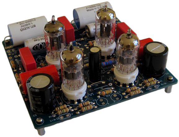
11 March 2018 Post 415 New Aikido Stereo Noval PCB
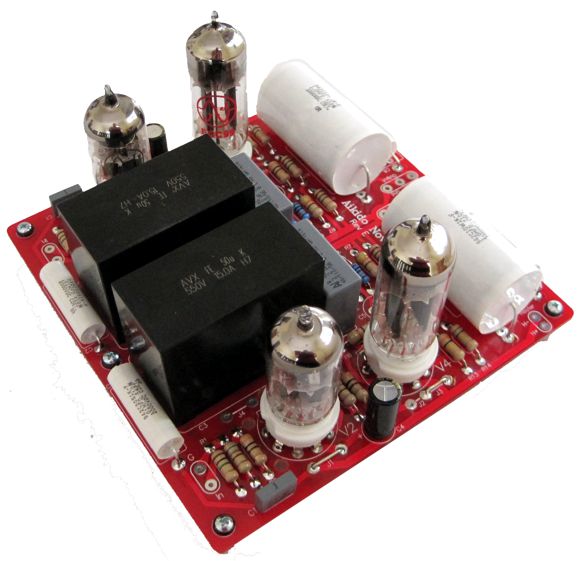
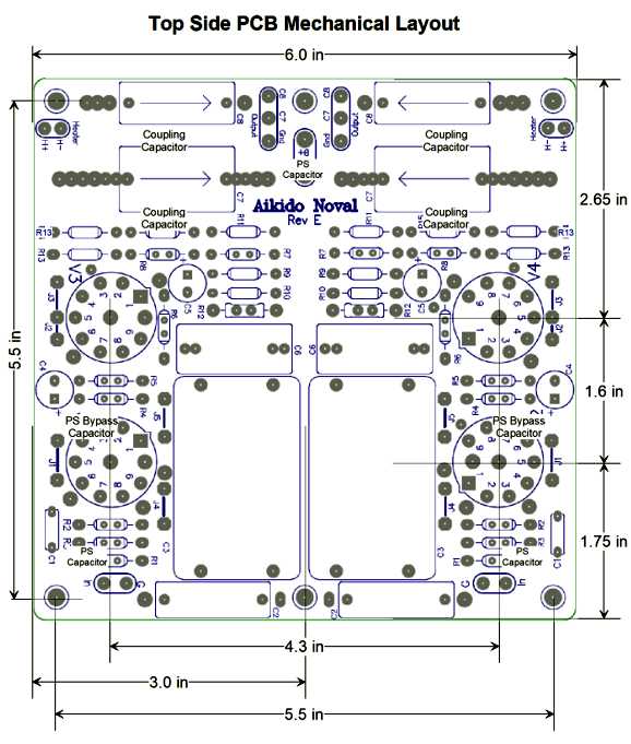
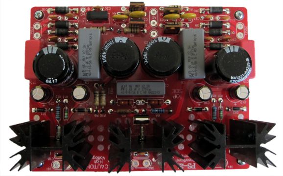
Aikido Noval Rev. E
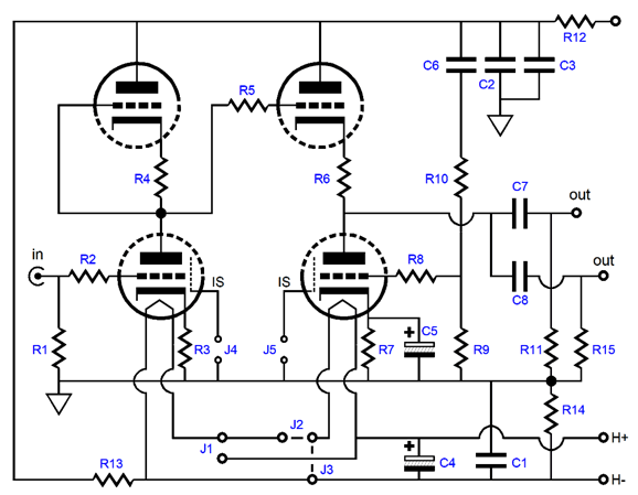
The two big black boxes each hold 50µF of polypropylene capacitor that is rated for up to 550V and 15A; each capacitor has for PCB-mount leads on its bottom. Obviously, they were not created with audio in mind, but some industrial application. But then precious few electronic devices were designed with audio in mind. "Audio must live on the crumbs that fall off the technology table." is how I put it back in 2001. Here is the schematic of one of the two Aikido line-stage amplifiers on the PCB.
Other than the shared B+ and ground connections, the two channels are independant from each other, which was the aim of this new revision. For over 20 years, I have been told by those whose ears I trust that giving each channel its own in dependant heater power supply improves the stereo imaging. How could that prove true? My guess is that the heater-to-cathode capacitance allows unwanted bleed-through of audio signals between channels. In a simple grounded-cathode amplifier, with a bypassed cathode resistor, this could hardly be that big a problem. But in a topology where the cathode moves about, such as the cathode-coupled amplifier and the Aikido gain stage, I can see how this unwanted and hidden coupling capacitor between the two channels could cause bleed-through. Note how the each channels' two heater elements can be placed in either series or in parallel with each other. Also note how the heater power supply is DC referenced to some voltage in between the B+ voltage 0V, due to the two-resistor voltage divider made up of R13 & R14. Well, I have finally built up a PCB and tested it, after some false starts due to my having made some wiring mistakes in spite of my measuring twice and soldering once. So, how does it sound to me. First off, I am the last person to ask, as I am the one person most invested in there being a sonic difference. Here I will quote myself quoting someone else:
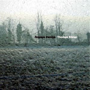
Second, the new revision of the stereo Aikido noval PCB hold two big differences, so whatever sonic differences are heard could be the result of just one change or two changes or due to some interaction between the two changes. Muddy waters, indeed. Nonetheless, here is what I heard, after my best effort to compare apples to apples by using the exact same resistor type and values, coupling capacitors, and tubes in the old PCB and in the new (in other words, I pulled the tubes out of the old Aikido PCB and I plugged them into the new one before listening), better imaging and more defined bass. My temptation was to use only high-res audio from Tidal's MQA library, but then I changed my mind. Although almost half of what I listen to these days is high-res, 99.5% of the music I love most is in the 16-bit, 44.1kHz lossless digital format. Interestingly enough, the CD-grade music sounded much more high-res through the new revised Aikido, as it took on more of that relaxed, effortless quality and small details seemed to be in sharper focus. I might have been deluding myself, but I thought the imagining improved more than a little. By the way, the whole point to expending any effort on audio systems is that you can nudge yourself into better liking music that you don't quite like right now. I believe that his helps explain why most audiophiles enjoy such an eclectic array of musical genres. Am I right? Think about it; how many normal people do you know who can only abide a slender slice of some genre, such as just 1980s soft rock or just bluegrass or just whatever is currently being played on the radio. In contrast, ask an audiophile if he or she would like to hear a great CD of Moroccan music that you just picked up, and my hunch is that, nine times out of ten, he or she will say yes. Well, I found myself thinking, as I played track after track, I really have to listen to the entire album again. Not a radical or transformation of my previous inclinations, but a enough of a nudge to make me dispel whatever prejudice I had held and give the music a more extended and fairer listen. For me, no other aspect of our hobby, such as snob appeal and status seeking, is as compelling. After about half an hour of listening, however, I began to worry that the bass was a tad shy. I then played some bass-monster recordings, such as the album, Novaya Zemlya, by Thomas Köner. No Worries.
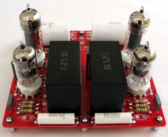
This interesting amassment, collection, conglomeration of sounds, not actual music, will test your subwoofers. (If you subscribe to Tidal, please do give it a listen, as it is a truly impressive and enjoyable listen.) Well, the bass was there, but due to it sounding tighter and more defined, it only seemed to sound leaner. Here is one of my signature crazy analogies: two men that weigh the same might appear to the eye not to weigh the same, if one is lucky enough to be endowed with a ripped, lean muscular body, while other is unlucky enough to be saddled with a soft, round, chubby body. In spite of what the weight scales tells us, the fat guy will look heavier, in spite of everyone knowing that muscle is denser and weighs more than fat. I experienced a similar false sensation long ago, when I first demagnetized my phono cartridge. All the damn highs were gone! Or were they? I wondered after about ten painful minutes filled with remorse at my folly. As I carefully listened, however, I realized that all the highs were there, but the high-frequencies grunge and shrillness was not. I had mistaken bad highs with more highs. I remember a stereo salesman telling me that customers, who are in a two-speaker shootout, always choose the speaker with the most cutting, strident highs and the speaker sporting the most neutral and natural highs always losing. So, which change gets the credit for the tighter bass? I would bet on the electrolytic-free power supply, although I have certainly heard a similar result when going from AC to regulated DC on the heater elements. So why would I bet on the film power-supply capacitor? I heard a truly similar change after I replaced a 47µF electrolytic power-supply capacitor in a friends phono stage with a 40µF polypropylene capacitor that was almost the size of a beer can, due to its high-voltage rating, 1kV. The new Rev. E PCB is the same size as the older Aikido stereo noval PCBs, but the tubes are located farther apart.
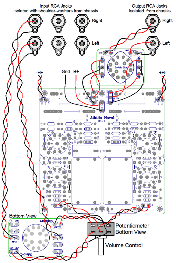
The actual wiring layout is simple enough.
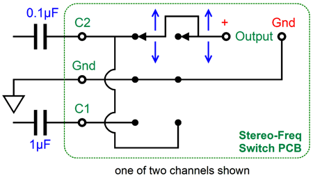
Where so many go wrong is by adding more ground wires than are needed. Unlike wearing a belt and suspenders, adding more ground wire makes things less secure, not more. For example, in the above layout each input RCA jack is entirely impendent from the other, as no common ground-bus wire connects them altogether; the same holds true for the two output RCA jacks; and the two grounding lugs on the volume control are NOT tied together. The switch at the output is a new item I just made: the Stereo-Freq switch. It differs from the Select-C switch in that it offers three positions: coupling capacitor 2, mute, and coupling capacitor 1 and 2 in parallel.
The idea behind the Select-C switch was that you could choose between two different types of coupling capacitor (or place both in parallel). The idea behind the Stereo-Freq switch is that you can choose between two low-frequency cutoff frequencies, say 10Hz and 100Hz or mute the signal. Why would anyone want to do this? Late-night or early-morning listening. Deep bass travels easily through your house or apartment. By selecting the higher low-frequency cutoff, we can listen without bothering others. Another possible use is to limit the lows to 60Hz, so a delicate dipole or mini-monitor speaker is not overdriven, but still have the option of going low with more robust speakers.
But the real reason I made this new switch was that I needed a rumble filter with LP playback, as some LPs are horrifically warped. With subwoofers, the unwanted low-frequency content was just wasting power and risking possible damage to the speakers. With the Stereo-Freq switch, I can limit the low-end extension when I play a warped record, but listen to fullrange with flat LPs. I am using 0.01µF and 1µF coupling capacitors on my phono stage.
As you can see from the above schematic, when we select C1, the larger-valued coupling capacitor, we also get C2, the smaller capacitor, in parallel with C1. In the middle position, we get mute. Returning to the new Aikido stereo PCB, the price we must pay for sporting two heater power supplies, other than having to provide two regulated heater power supplies, is that we become more limited in possible tube selection. For example, we could use a 6CG7 as the input tube and a 6DJ8 or 6H30 as the output tube, but then we must use a 6.3Vdc heater power supply, as we cannot place the two heaters in series, due to each tube type drawing a different amount of current. On the other hand, we can use two identical 6.3V tubes, say two 6CG7 or two 6DJ8 or two 6AQ8 tubes and place the heaters in series and use a 12.6Vdc heater power supply. In my test build, I used a 12AU7 as the input tube and an ECC99 as the output tube, a fine-sounding combination by the way, with a regulated 12Vdc heater power supply per channel.
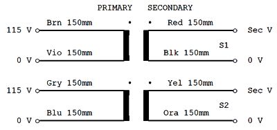
The power supply I used was, of course, my new PS-21, which I created with this application in mind and which offers a regulated B+ voltage two independent heater regulated power supplies. In my sonic shootout, the old stereo noval PCB was attached to a PS-1. Powering the two heater regulators was easy enough, as the toroid power transformer I used held two identical 12Vac secondaries.
The Aikido noval stereo boards and part kits and Stereo-Freq switch are available now at the GlassWare/yahoo store. If you have been tempted to try an Aikido preamp (i.e. line-stage amplifier) out, this is the one to try.
Why Tubes? Almost all musicians who use electric instruments already know all about the sonic glory of tubes. Those musicians who don't plug their instruments into anything other than your ears and soul, usually don't know anything about tubes. In a fine restaurant in Palo Alto, California, I once overheard a group of concert musicians from a local symphony tease one of their fellow musicians for being not only being an audiophile, but a tube-loving audiophile. "Tell them how much you speakers cost," he was urged to reveal and his evening went steadily downhill from that second on, as his fellow musicians laughed at his expensive folly. This happened so long ago that the most expensive power cord you could buy still cost less than $100. In fact, if I remember correctly, his system only neared $20,000, which today would hardly prove enough to buy a decent pair of loudspeaker cables. Did I boldly reenact the American composer, Charles Ives, when he told a group of hissers at a concert of modern music to "Stand up and take your dissonance like a man," by pointing my angry finger at them and telling them to "Stand up and take his high-end audio like a man?" No. Why not? I was on a date and I didn't want her to know that I was devoting anything less than 100% of my attention to her. So, he was on his own. In fact, he dug himself a deeper hole by arguing that his $$$ stereo system should be tax deductible, as he needed its higher resolution to allow him to hear the violin fingering techniques used, so it was really a business expense, not a luxury purchase. Peals of laughter. He was doomed. No doubt each of you can tell a similar story or two. No doubt you know that bewildered look of incomprehension that meets your recounting your interest in tube audio, the sort look you yourself would wear if someone told you that they collected bellybutton fluff as a hobby. I have read about audio's missing generation, which is made up of those who came of audio age during the almost two decades of MP3 dominance, and who have had no experience of high-quality sound, and who are not likely to ever become audiophiles later in life. Maybe. But perhaps not, as most teenage boys seem to hunger for better, more expensive headphones. And when I show them my stereo system, theirs zero in on the turntable. A year ago, I was shocked to see LPs being sold in Barnes and Noble bookstores. Last month, I was flabbergasted to see 180-gram LPs being sold in Walmart. Walmart, for God's sake, Walmart. There is hope. Like the poor and the rich, tubes will always be with us. Even if solid-state catches up and finally surpasses the vacuum tube, tubes will still be valued, as by their warm glow and by their temporal redolence of a happier past, they sidestep the modern existential quagmire. And if you can forgive excessive outpourings of synesthesia, Tubes incandense like Victory.
Copies and Reproductions and Retro-New In contrast, a museum in Philadelphia might commission the making of a replica of his desk, which would not only consist of materials available in Ben's time, but fabricated using the tools of his time. If the museum were a tad less fussy, they might order just a reproduction, which would consist entirely of old-time materials, but made using whatever tools are presently available. True, these are subtle distinctions, but all important differences for those in the know. (If you know anyone with a restored NOS American muscle car filled with same-era American-made replacement parts as opposed to a restored old car filled with new parts from China, then you have a good idea how fanatical some enthusiasts can be.) Because vacuum tubes, capacitors, resistors, and transformers were all available in the 1950s, we can not only build circuits from the 1950s, but we can design circuits that could have been built in the 1950s. For example, the Aikido could have easily been built in 1950, if we had a time machine to send back the schematic. If I had but a fraction of Bill Gates* money, I would throw here in the United States the equivalent of the European Triode Festival (ETF), a Retro Audio Festival (RAF), where big cash prizes would be awarded for winning home-made retro audio gear, preamps, power amplifiers, and other tube-based audio equipment. The rule would be simple enough: anything goes as long as it could have been made in 1960. By the way, this is not as limiting as you might imagine, as 1% metal-film resistors and Teflon capacitors were available back then—at great cost it is true, but available nonetheless. Although the parts might wear a long white beard, the topology could be newborn. This would lend an interesting time-machine and what-if quality to the contest. Of course, you could do the exact opposite: hold a contest where only old-time schematics were allowed, but all the parts, including the vacuum tubes, would be of modern fabrication. By the way, here is a story that I do not believe that I have mention before—nor does Google, as my search returned no links. About 25 years ago, a sweet old-timer, Roy, who I liked so much that I called him "Dad" and he called me "Son," told me that he had a bunch of tubes that I might interested in. He was right, as a few gems hid in moldy boxes, although most of the tubes were obviously intended for radio use, not audio. I asked how he came by this NOS treasure and he told me the amazing story. A neighbor of his was remodeling his garage and pulled away the half-century-old wood paneling, revealing a store of electron parts hidden in between the 2 by 4 studs. During the 1960s, a young radio enthusiast had either joined the Army or was drafted and he hid his stash of goodies. He died in Vietnam; his parents moved; and the electronics parts remained hidden for decades. When found, the parts were given to Roy, as he was widely known as a devoted ham-radio operator. So far, not a bad story. What makes it vastly more interesting, however, is that hidden along with the parts was a notebook, a spiral-bound notebook filled if hand-drawn schematics. I never saw the notebook, as it was in the possession of a Stanford University electrical engineering professor. The young soldier had been a genius, as his notebook held schematics of circuits that were only invented years after his death. Had he lived, he might have become the equivalent of the radio-version of Bob Pease.
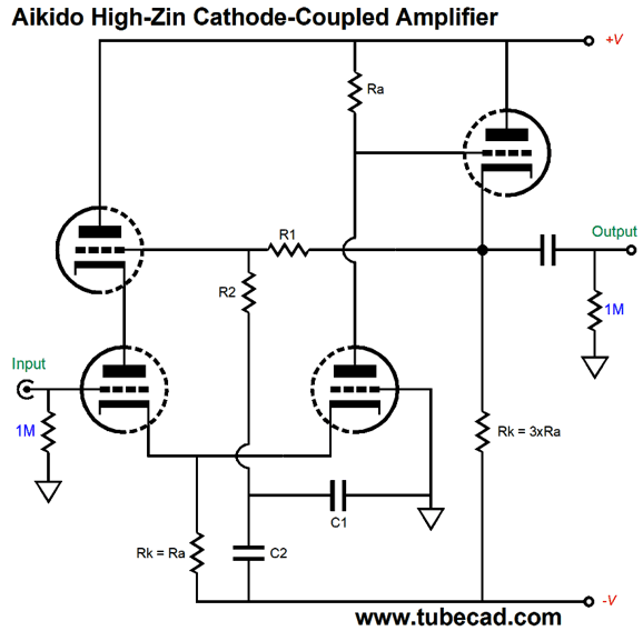
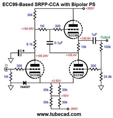
Old-School Cathode-Coupled Amplifiers Sticking to the no-later-than-1960 rule mentioned above, we cannot make use of IC constant-current sources or high-voltage MOSFETs. But the amazing thing is, when it comes to tubes, that we can achieve so much with so little. For example, the Aikido high-input-impedance cathode-coupled amplifier offers fantastic performance, but requires few parts.
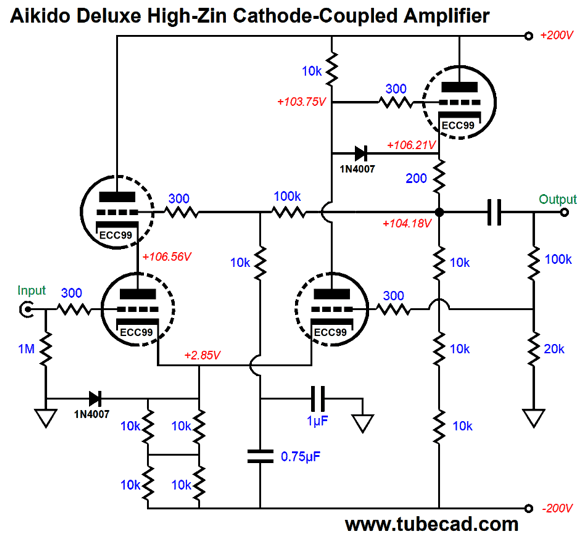
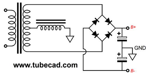
This circuit could have been built in 1960, as all the parts were readily available back then. A high-voltage, bipolar power supply and two dual triode tubes are required—along with a few resistors and capacitors. Not much at all really. What is essential, however, is that the part values be carefully chosen. Resistors R1 & R2 define a two-resistor voltage divider that ensure that the input triode's grid-to-plate capacitance is neutralized. Capacitors C1 & C2 must be selected to inject just enough power-supply noise from the B- power-supply rail to force a power-supply noise null at the output. Let's flesh out the design based on the ECC99 tube. (In 1960, they would have used a 5687.)
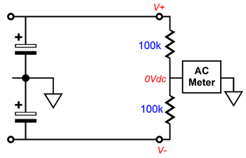
Due to the ECC99 triode's low plate resistance, 2300 ohms, and its high transconductance, we can run relatively low bipolar power supply rail voltages; in this example, just +/-200Vdc. The long-tail shared cathode resistor is made up of four 10k resistors in series-parallel, resulting in a combined resistance of 10k, but at four times the wattage of one 10k resistor. With 200V across a 10k resistance, we will see a heat dissipation of 200²/10k or 4W, which means that 2W or 3W 10k resistors should be used. The cathode follower uses three 10k cathode resistors in series to spread the 3W of heat across the three resistors; in addition, the three resistor in series help prevent voltage-induced distortion, which some resistors are prone to. The 100k and 10k voltage divider resistors ensure that the input triode's plate will move up and down in voltage by the same amount that its grid does. The 1µF and 0.75µF capacitors leak enough of the negative power-supply rail noise to create a power-supply noise null at the output. The 100k and 20k resistors form a negative feedback loop that sets the cathode-coupled amplifier's gain to 4 or +12dB. The two 1N4007 diodes are simply protection devices that prevent excessive positive grid voltage relative to the cathode from developing at start-up, with the cathodes are cold and not yet conducting. The assumption behind this design is that both of the bipolar-power-supply rails exhibit the same amount of ripple, ripple that is equal in magnitude but out of phase between rails. Why wouldn't this always obtain? Well, the two rails might not be equally burdened, as the positive rail might also power a phono preamp. Another possibility is that the power supply reservoir capacitors are not matched in value. Most high-voltage electrolytic capacitors are marked 20%, although some spot measuring finds vastly tighter tolerances than 20%. The last possibility is that the power transformer's secondary is mis-tapped, so center tap does not fall at exactly 50% of the winding. The quick test for a mis-tapped secondary is the measurement of the ripple frequency, which should be twice the wall voltage frequency, so 120Hz in the USA and 100Hz in Europe. The other test would be to simply measure the AC voltage at each end of the secondary relative to the center tap or we could place a two-resistor voltage divider between rails and measure the AC signal present at the junction relative to ground; ideally, no AC signal should be present.
Two workarounds are possible: add a series resistor to the stronger half of the secondary; or, place either a resistor, say 100 ohms, or an inductor in series with the center-tap and the power supply ground. The inductor is the better choice. In fact, I know a few solder-slingers who always place an inductor in series with the power transformer primary, which both lowers the B+ voltage and softens the ripple shape, smoothing away the jagged edges.
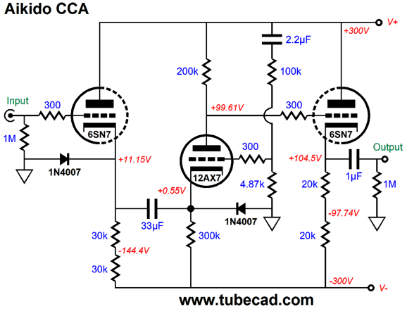
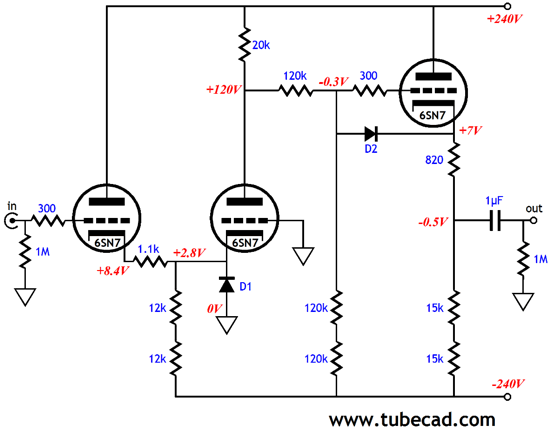
Let's move on to another retro-new circuit. The following design also uses a bipolar power supply and common, old-school parts.
The nested 12AX7 triode provides all the signal gain, while the two 6SN7 triodes buffer. Note how the problem of dissimilar cathode-to-grid voltages is overcome by the 33µF capacitor. This capacitor connects the two cathodes in AC terms, but lets each triode find its own DC cathode operating point. The 12AX7's grid receives a portion of the B+ voltage ripple through the 100k and 4.87k voltage divider resistors. The rightmost 6SN7 triode functions as a straightforward cathode follower. If we look at this circuit a little more carefully, we realize that the 2.2µF capacitor really isn't needed.
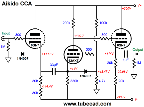
Note how the 300k cathode resistor was replaced by a 330k resistor and how the 12AX7 cathode now sits at a higher DC voltage than the input 6SN7 triode's cathode. On both of these circuits, the 1N4007 diodes are just protection devices that are not forward biased during normal operation. If we are willing to use some modern solid-state devices. We can forgo the need for a bipolar power supply.
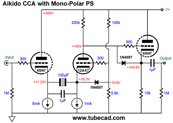
Note the 100µF non-polar electrolytic capacitor in place of the 33µ film or PIO internal coupling capacitor. This replacement capacitor gets a 1µF bypass capacitor. Only two protection diodes are needed, although a good case could be made for using just one, the one that protects the cathode follower's triode. The 12AX7 provides a lot of gain, which may or may not be needed. If the 12AX7 was replaced by a 6J5 (a tube that holds a single 6SN7 triode), then the gain would fall dramatically, but the center triode's idle current would dramatically increase, say to 5mA.
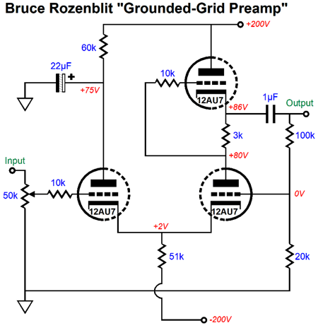
Cascoded and SRPP Cathode-Coupled Amplifiers
The plate resistor has been replaced by an active load made up of another 12AU7 triode and its cathode resistor. The resulting impedance of the active load is equal to rp + (mu +1)rk; with the 12AU7 and the 3k cathode (Rak) resistor we something close to 60k. Note the light current flow through the 12AU7 triodes, just 2mA. Because the output is taken at the top 12AU7's cathode and not below its cathode resistor, this SRPP stage can perform some push-pull current swings. In other words, with the right load impedance, we might get up to twice the idle current into an external load. So what would be the optimal load impedance for Bruce's circuit? The formula for the optimal Rak resistor value is: Rak = (rp + 2Rload) / (mu - 1) If we solve for Rload, we get Rload = [(mu - 1)Rak - rp]/2 This puts us at about 20k. I, on the other hand, given three 12AU7 triodes per channel, would prefer my CCA design from post 245 and post 302, as this design an Aikido mojo power-supply noise null and a far lower output impedance and it places all the cathodes near ground potential
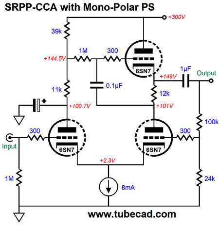
But if I had to stick to the SRPP theme, I would try the following design, which uses a much larger Rak resistor.
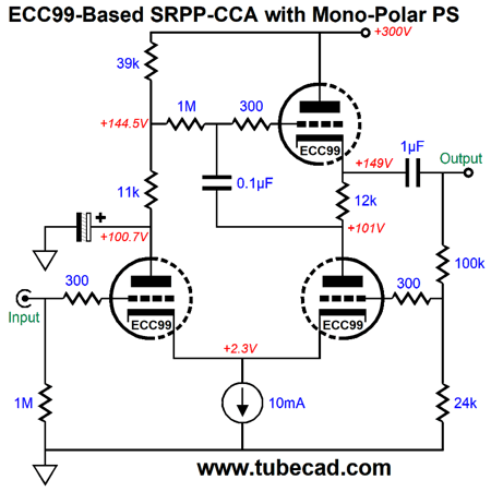
Note that no negative power-supply rail was used, although the solid-state constant-current source could be replaced with a long-tail shared cathode resistor and a connection to a negative power-supply rail. If a lower-rp/higher-transconductance triode were used, say a 6DJ8, 6H30, 12BH7, 5687, or ECC99, then we could get away with a lower B+ voltage, say only +200Vdc. Keeping the same 300V B+ voltage, the following design based on the ECC99 would make a fine line-stage amplifier.
I find the 5mA per leg idle current a tad wimpy, but if we tried doubling the constant-current source's idle current to a robust 20mA, we would see the common cathodes drop too low in voltage to get away with not using a negative power-supply rail. Remember the tied cathodes will follow the input triode's grid, so if -1Vpk enters the grid, the cathodes should drop down in voltage by-1Vpk as well, which could voltage starve the solid-state constant-current source. Of course, as little a -5Vdc from a negative power-supply rail would prove plenty for the constant-current source. If a -300Vdc negative power-supply rail were used with big long-tail shared cathode resistor, then a safety diode must be used.
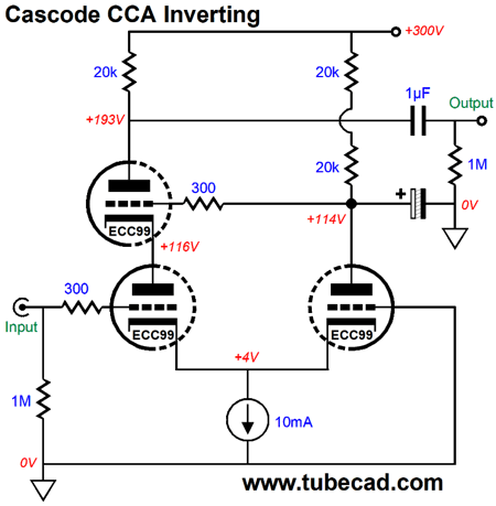
Without the safety diode, at start-up, the bottom two triodes would see -300Vdc on their cathodes and 0Vdc on their grids. Not good. The four 30k cathode resistors present a combined resistance of 30k and each resistor will dissipate 0.75W. (I would actually use six 20k in a series parallel arrangement.) Adding a cascode to the cathode-coupled amplifier gives us two possible configurations: we could cascode the left input triode or the right cathode-coupled amplifier triode. If we cascode the input triode, the output will be out of phase and the right triode's grid cannot be used a negative feedback port, without adding an additional inverting stage after the cathode-coupled amplifier.
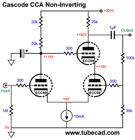
In either configuration, the Miller-effect capacitance is sidestepped. My policy is to never throw away any topology, as you never know when it might be the long-sought solution to some major problem. Nonetheless, I know that most would be more interested in the following variation.
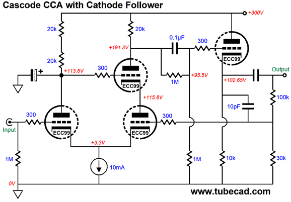
No phase inversion at the output and wide bandwidth and high gain obtain. The 100k and 30k voltage divider resistors form the negative feedback loop and set the gain to 4 or +12dB. The open loop gain in SPICE simulation was 48 (+33.6dB), so the amount of negative feedback is equal to 33.6dB -12dB (or 21.6dB). With the feedback loop closed, the output impedance is a little over 1200 ohms. The distortion was so low that I won't bother showing the Fourier graph, as I am sure that reality will disappoint in comparison to the graph, yet prove extremely fine. There is much promise here. If we are willing to add an additional triode, we can add a cathode follower output stage, which will dramatically reduce the output impedance.
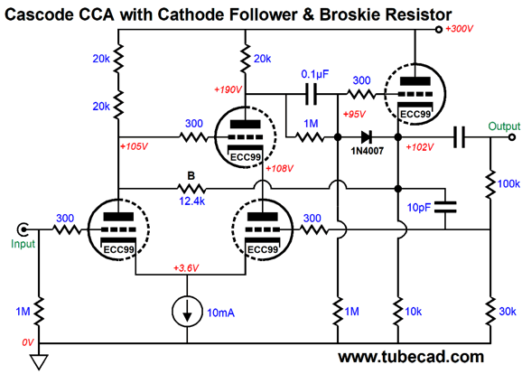
The cathode follower ECC99 triode idles at a hot 10mA, which can easily burn through long high-capacitance interconnects. The cathode follower is half DC and half AC coupled to the cascoded cathode-coupled amplifier, as the 0.1µF internal coupling capacitor is shunted by a 1M resistor. In other words, 50% of the DC passes, while 100% of the AC gets through (well, at least in the audio band of frequencies). Why use this setup? I wanted to give the cathode follower more cathode-to-plate voltage and I wanted to keep its cathode closer to ground potential, so that all four triodes could share the same 12Vdc heater power supply that is referenced to +75Vdc. The lone 1N4007 diode protects the cathode follower triode at start-up. The 10pF capacitor effectively shunts the 100k negative feedback resistor, which prevents high-frequency instability. The unmarked electrolytic capacitor could be any value between 20µF to 100µF. Although a large film capacitor could be used instead, I would rather use my signature cathode-coupled amplifier resistor that bridges the input triode's plate to the cathode follower's output.
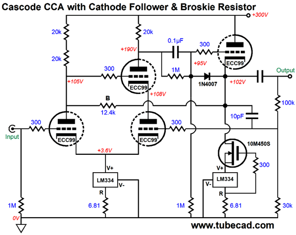
This resistor (B), which we can call the Broskie resistor as I cannot think of any descriptive name for it, is selected to allow the cathode follower to tug the input triode's plate the same amount and the same phase as the input triode's grid gets moved by the input signal, which neutralizes the input triode's grid-to-plate capacitance. By using this resistor, which only sees a few volts of potential difference across its leads, we both lower the input impedance and eliminate the need for the big shunt capacitor. Reader and patron, Krzysztof, asked if replacing the 10k cathode resistor would not improve the performance. It would. Here is how I would try to do it.
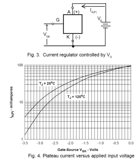
The 10M45S wants to see about +3V of cathode voltage relative to its gate.
This 3-volt voltage window is easily enough to make the LM334 happy.
Hybrid Cathode-Coupled Amplifiers
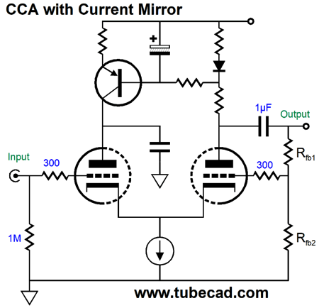
Note that the negative feedback loop sets the gain in this circuit, which can never exceed the triode's amplification factor (mu). Since a cathode-coupled amplifier deconstructs into a buffer driving a grounded-grid amplifier's cathode, we can use a solid-state buffer to do the driving or a combination of vacuum-state and solid-state devices.
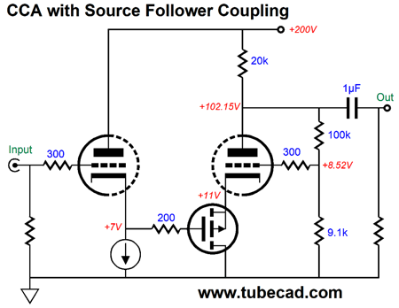
The input cathode follower drives the source follower which in turn drives the grounded-grid amplifier's cathode. Note the voltage drops and note how the negative feedback loop attaches on the hot-side of the coupling capacitor. Why? We need both AC and DC feedback to force output where we want it. So far, one constant-current source is used. We could replace the plate resistor with a constant-current source; although the gain would rise, the PSRR would slightly worsen. There is no paradox here, as the input triode's plate sees 100% of the B+ voltage ripple, which will be relayed through to the output. The workaround is the following design.
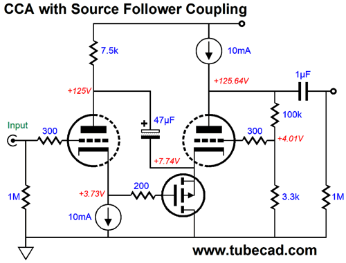
The 7.5k plate resistor and the 47 µF capacitor form an RC filter that shields the input triode's plate from the power-supply noise. The P-channel MOSFET's source can easily push the 47µF capacitor up and down. The result is a neutralization of the input triode's grid-to-plate capacitance and a vast improvement in PSRR, which is helped by the second constant-current source that loads the output triode. Well, couldn't we make things even better by replacing the 7.5k plate resistor with a constant-current source? No. Why not? In general, you never want to place two constant-current sources in series. On the other hand, if replaced the plate resistor with a compliant-constant-current source, all would be well.
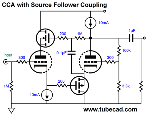
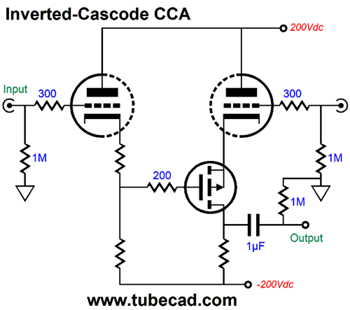
Be warned, I have yet to model this circuit in SPICE, so there might be some hidden wrinkles. We have already covered some cascoded cathode-coupled amplifiers, but by going hybrid, we have more possibilities open to us. The following is one such example.
This is an inverted cascode that uses a high-voltage bipolar power supply. Since almost all of the output triode's transconductance is preserved, we can expect high gain. With some tweaking, we can even get a fine PSRR. (Start by making the drain resistor's value equal to the triode's rp.) This circuit actually falls out of the cathode-coupled amplifier grouping, as it accepts a balanced input signal, making it more of a differential amplifier. In addition, the output is inverted in phase relative to the left triode. Okay, are we finally done with the cathode-coupled amplifier? For now, definitely. I could actually squeeze another post on this topic, but I lack the will. Moreover, I want to move on to other topics. But you can bet that this will not be my last post on the cathode-coupled amplifier.
//JRB
*Bill Gates So, what should he do with his billions and his generally poor reputation (Steve Jobs' reputation only grows)? As Nietzsche so wisely pointed out,
The world needs justifying, particularly America, as so much of America is plain, butt-faced ugly, completely devoid of aesthetic sensibility. At times I even wish that the Spaniards and Napoleon had each kept their one third of America to themselves, as at least that way 66% of cities would be far more attractive. In other words, Bill, spend your remaining time and money on making either a few huge, beautiful things, such as the Eiffel Tower or the Sydney opera house; or make many small beautiful things like hundreds of public rose gardens or small computer-technology museums throughout America. Oh, John. How insensitive! Remember in the Bible when the woman is rebuked for applying an expensive ointment to Jesus, oil which could have been sold and the proceeds given to the poor, and Christ said, :... Leave her alone. She has done a beautiful thing..." Well, he was dang right; period.
User Guides for GlassWare Software Since I am still getting e-mail asking how to buy these GlassWare software programs:
For those of you who still have old computers running Windows XP (32-bit) or any other Windows 32-bit OS, I have setup the download availability of my old old standards: Tube CAD, SE Amp CAD, and Audio Gadgets. The downloads are at the GlassWare-Yahoo store and the price is only $9.95 for each program. http://glass-ware.stores.yahoo.net/adsoffromgla.html So many have asked that I had to do it. WARNING: THESE THREE PROGRAMS WILL NOT RUN UNDER VISTA 64-Bit or WINDOWS 7 & 8 or any other 64-bit OS. One day, I do plan on remaking all of these programs into 64-bit versions, but it will be a huge ordeal, as programming requires vast chunks of noise-free time, something very rare with children running about. Ideally, I would love to come out with versions that run on iPads and Android-OS tablets.
//JRB |
John Says Thanks the Special 70 Only those who have produced a technical white paper or written an article on electronics know just how much time and effort is required to produce one of my posts, as novel circuits must be created, SPICE simulations must be run, schematics must be drawn, and thousands of words must be written.
If you have been reading my posts, you know that my lifetime goal is reaching post number one thousand. I have 585 more to go. My second goal is to gather 1,000 patrons. I have 930 patrons to go.
And
High-quality, double-sided, extra thick, 2-oz traces, plated-through holes, dual sets of resistor pads and pads for two coupling capacitors. Stereo and mono, octal and 9-pin printed circuit boards available.
Designed by John Broskie & Made in USA Aikido PCBs for as little as $24 http://glass-ware.stores.yahoo.net/
The Tube CAD Journal's first companion program, TCJ Filter Design lets you design a filter or crossover (passive, OpAmp or tube) without having to check out thick textbooks from the library and without having to breakout the scientific calculator. This program's goal is to provide a quick and easy display not only of the frequency response, but also of the resistor and capacitor values for a passive and active filters and crossovers. TCJ Filter Design is easy to use, but not lightweight, holding over 60 different filter topologies and up to four filter alignments: While the program's main concern is active filters, solid-state and tube, it also does passive filters. In fact, it can be used to calculate passive crossovers for use with speakers by entering 8 ohms as the terminating resistance. Click on the image below to see the full screen capture.
Tube crossovers are a major part of this program; both buffered and un-buffered tube based filters along with mono-polar and bipolar power supply topologies are covered. Available on a CD-ROM and a downloadable version (4 Megabytes). |
||


| www.tubecad.com Copyright © 1999-2018 GlassWare All Rights Reserved |