| John Broskie's Guide to Tube Circuit Analysis & Design |
25 January 2018 Post 410
We continue with single-ended amplifier designs. True, they are super simple, but they are also less forgiving. I have heard musicians say that learning to play the bass is easy, but playing it well takes supreme talent. (I have heard this notion applied to the saxophone as well.)
Class-A2 and Single-Ended "He was still running his Linn turntable, but with the new Schroeder tonearm and the Soundsmith Zephyr cartridge, with a VAC preamp …" A more complex example, but still filled with mirth-making potential, might be amplifier classes of operation, which are a ridiculous mess, only made messier by glossy ads in audio magazines. Class-A by itself is one huge box of tangled junk parts, further jumbled by the makers of high-end class-A amplifiers, amplifiers that supposedly exceed the theoretical maximum efficiency 50% for any class-A amplifier. (I get email that asks, "What do mean by saying that you can't get 60W of class-A power from a pair of KT88s" Company Z does it all the time.") As I understand it, many believe that any power amplifier that uses cathode bias is, by that fact, running in class-A. Alas, it ain 't so. At the RMAF, I asked the maker of a single-ended amplifier that held one 25W output tube how could the single tube possibly be delivering 25W of output, as that would imply at the very least 50W of dissipation from the output tube, with a more realistic implication of 100W of dissipation? His answer was that the tube was good for more than 25W, besides he was running class-A2.
If Samuel Johnson were alive today, he would no doubt say that class-A2 is the last refuge of a scoundrel. Why? A class-A2 amplifier requires extra effort, not less. Here is an analogy: your friend tells you that he plans to walk to a faraway city for lunch. You point out that the city is 60 miles away, so he might be able to eat dinner there the next day, but never lunch today. He laughs at your foolish comment and informs you that he plans on running the last 20 miles. How could you have forgotten that running requires far less effort than walking, with an all-out 100-meter dash being easiest of all? I went on to ask if he used a cathode follower to drive the output tube's grid. He didn't, he just used a coupling capacitor. A scoundrel, indeed. Class-A2 means that we purposely allow the output tube to enter positive-grid bias, so that the usually super-high impedance grid becomes a low-impedance load as the grid begins to conduct current; when the grid goes positive relative to the cathode, the grid becomes a forward biased diode with the cathode. If we don't prepare for the abrupt decrease in grid resistance, class-A2 goes wrong, with the coupling capacitor charging up excessively, making the output tube see too negative a bias voltage. In contrast, a cathode follower driving the grid positive can suck up the sudden increase current flow.
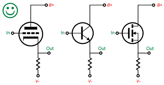
In short, class-A2, like running a 100-meter dash, is not easy. It requires great care and thought. And class-A2 certainly does not exceed the theoretical maximum efficiency 50% for any class-A amplifier. If you plan on building a class-A2 amplifier, then also plan on using either a cathode follower or source follower or emitter follower to drive the grid positively. Why? Once the grid begins to suck up current from the cathode, it must go somewhere that ultimately terminates in the B+ voltage: alas, a 0.1µF coupling capacitor does not count; nor, do all possible followers.
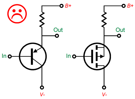
These three followers are all acceptable. In contrast, the following two followers are unacceptable, if the load resistor value is too high in value.
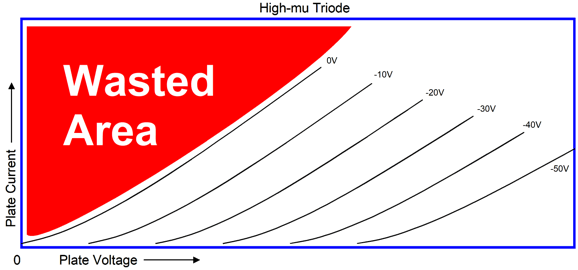
With too high a load resistor value, the PNP transistor and the P-channel MOSFET can lose control of the grid, as they can turn-off altogether, if the grid draws too much current. When does class-A2 make sense in a single-ended amplifier? The higher the output triode's amplification factor (mu), the more sense it makes; conversely, the lower the mu, the less sense it makes.
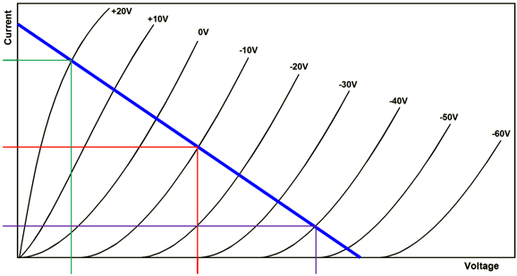
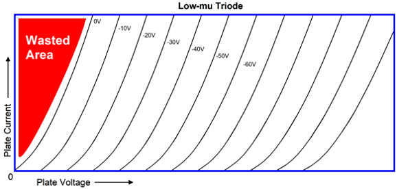
The high-mu triode wastes much of the B+ voltage due to its high plate resistance. Class-A2 operation allows us to reclaim much of the portion to the left of the 0V grid line; which if nothing else, allows us to run a lower B+ voltage. In contrast, the low-mu, low-rp triode does not offer much area to the left of its 0V grid line.
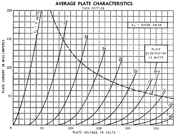
So, why doesn't everyone use low-mu triodes? In general they do. The 2A3, 300B, and 845 all exhibit a low mu. The downside to a low mu is that much bigger input signal is needed to achieve full output.
A good example is the 6AS7 (6080) triode with its mu of 2, which requires truly huge grid-voltage swings to dance, as its plate curves shown above illustrate.
Where does a pentode fit in this situation? Mostly, it doesn't. The pentode sort of combines positive-grid current with negative-grid voltage, as its grid-1 is limited to negative voltages, but is grid-2 is always positively biased and always conducts current. As they saw it 100 years ago: the best of both worlds. Well, why isn't the pentode the best? Yes, we gained much in terms of efficiency, but we paid by giving up a low plate resistance, which gives the pentode its high plate resistance.
For a good detailing of class-A2 operation, check out post 364 and post 365, where you find designs like the one above. In addition, post 364 happens to be one of my favorites. (When I first posted this schematic, two readers wrote to me: they hadn't seen the 215V cathode voltage, only the 10V filament voltage. )
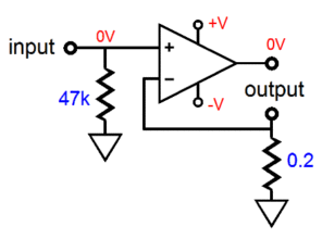
Current-Output Single-Ended Amplifier Now, 2-ohms is staggeringly high, as is the 4 ohms presented by some single-ended tube amplifiers, when compared to solid-state designs, but it is trivially diminutive when compared to infinite ohms, which a true current-output amplifier would present as its output impedance. So, with some seeming paradox, we need to use negative feedback to achieve a truly high output impedance from a triode-based current-output amplifier to overcome the triode's relatively low plate resistance.
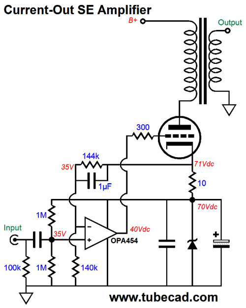
The above design is a hybrid effort. The high-voltage OpAmp drives and auto-biases the output tube. The OpAmp strives to see its input signal superimposed across the 10-ohm cathode resistor. Assuming that 1Vpk should bring the amplifier to full output, then the 10-ohm cathode resistor imposes a voltage-to-current ratio of 100mA/1V. The 144k and 140k resistors in the two-resistor voltage divider establish an idle current of 100mA, as the 1V across 10-ohms equals 100mA. (If you are wondering where to by a 144k resistor, you can place three 432k resistors in parallel.) The 1µF feedback capacitor couples 100% of the audio AC signal across the 10-ohm cathode resistor to the OpAmp's inverting input. As far as the high-voltage OpAmp is concerned, it is functioning as a unity-gain buffer, working into a 10-ohm load impedance. Since the triode supplies all the current flowing through the 10-ohm resistor, all the current variation through the resistor will also flow through the output transformer's primary. The output tube's plate resistance approaches infinity, due to the high negative feedback supplied by the OpAmp. The high plate output impedance delivers us a bonus in the form of a stellar PSRR, as the power-supply noise cannot alter the output tube's current flow, so this noise becomes invisible to the output transformer and loudspeaker. Note that the OpAmp's output centers at 40V, not 35V. Why? Triodes are easier to turn on than to turn off, so we need to be able to swing more negatively than positively. (If I had a few more cups of coffee in me, I could probably figure out how to move the cathode resistor below the zener diode. View this idea as an extra-credit homework assignment.) By the way, Linear Technology, now owned by Analog Devices, makes an interesting high-voltage OpAmp, the LTC6090, that can withstand a power supply voltage differential of 140V; for example,+70Vdc and -70Vdc power-supply rails or 0Vdc and +140Vdc. That is a lot of voltage. Indeed, it opens up many new possible hybrid OTL designs.
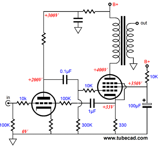
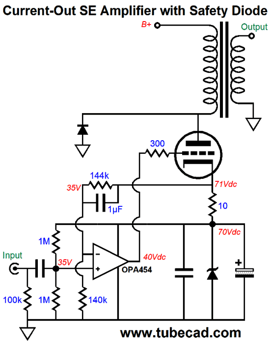
I have shown many, dang many possible current-output, pure-tube efforts in previous posts, such as the one above from post 216. Both the pure-tube and hybrid designs share a feature: the output transformer. Think about this: what is the worst thing that can happen to your voltage-output power amplifier? Answer, a dead short of the outputs. What is the worst thing that can happen to a current-output amplifier? Answer: an open circuit, say you trip on the speaker cable and it falls off the back of your loudspeaker. With the output transformer in place, this becomes less of a concern, as the amplifier will strive to swing current into the open circuit, but the output transformer's primary will offer at least its DCR. Worst-case, the output tube might see some arcing, due to huge plate voltage swings, but these could be lessened by adding a zener clamp to limit the potential plate voltage swing. (A 1N4006 rectifier bridging plate to ground might prove adequate, as it's 800V break-down voltage would limit the plate voltage swings to +800Vpk to 1Vpk, assuming a B+ voltage of 400V; with a B+ voltage of 500V, I would try a 1N4007.)
Under normal operation, the diode isn't there, as it isn't forward biased. But if the plate voltage swings below -0.7V or swings above the diode's breakdown voltage, the diode conducts.
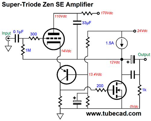
Super-Triode Zen SE Amplifier
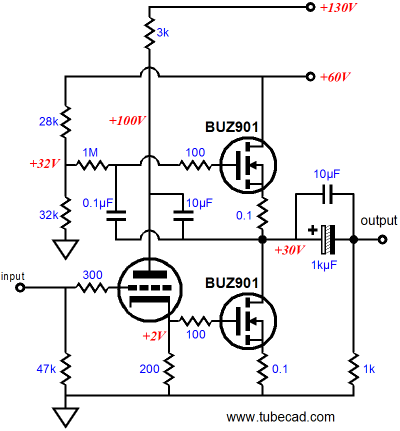
With the monopolar 24V power supply, we can expect an output power of about 6W into 8-ohm loads. The novel feature here is that the triode auto-centers the output stage to 12V. If the voltage goes above 12Vdc, the triode increases its conduction and the MOSFET does as well, as it would see its gate voltage go up, which would then pull the voltage down to 12V. If the voltage drops below 12Vdc, the triode will conduct less current, which will decrease the voltage drop across the collector resistor, which will prompt a lower current draw from the N-channel MOSFET, which in turn will allow the constant-current source to pull the voltage up to 12Vdc. This design is similar to the circuit shown in post 178, as shown below.
Both designs are Super-Triode efforts. The older design used the triode to set the bottom MOSFET's idle current, but did not center the output stage, as it came already auto-centered. The newer design is far more realistic, as its 24V power-supply rail voltage will generate 36W of heat at idle, which is plenty hot. This type of class-A amplifier is only 16%, not 25% let alone 50%, efficient. The new design also assumes that the far easier to find and far cheaper IRFP250 power MOSFETs will be used, rather than the more expensive and rare lateral types.
//JRB
User Guides for GlassWare Software Since I am still getting e-mail asking how to buy these GlassWare software programs:
For those of you who still have old computers running Windows XP (32-bit) or any other Windows 32-bit OS, I have setup the download availability of my old old standards: Tube CAD, SE Amp CAD, and Audio Gadgets. The downloads are at the GlassWare-Yahoo store and the price is only $9.95 for each program. http://glass-ware.stores.yahoo.net/adsoffromgla.html So many have asked that I had to do it. WARNING: THESE THREE PROGRAMS WILL NOT RUN UNDER VISTA 64-Bit or WINDOWS 7 & 8 or any other 64-bit OS. One day, I do plan on remaking all of these programs into 64-bit versions, but it will be a huge ordeal, as programming requires vast chunks of noise-free time, something very rare with children running about. Ideally, I would love to come out with versions that run on iPads and Android-OS tablets.
//JRB |
Special Thanks to the Special 61 Only those who have produced a technical white paper or written an article on electronics know just how much time and effort is required to produce one of my posts, as novel circuits must be created, SPICE simulations must be run, schematics must be drawn, and thousands of words must be written.
If you have been reading my posts, you know that my lifetime goal is reaching post number one thousand. I have 590 more to go. My second goal is to gather 1,000 patrons. I have 939 patrons to go.
And
High-quality, double-sided, extra thick, 2-oz traces, plated-through holes, dual sets of resistor pads and pads for two coupling capacitors. Stereo and mono, octal and 9-pin printed circuit boards available.
Designed by John Broskie & Made in USA Aikido PCBs for as little as $24 http://glass-ware.stores.yahoo.net/
The Tube CAD Journal's first companion program, TCJ Filter Design lets you design a filter or crossover (passive, OpAmp or tube) without having to check out thick textbooks from the library and without having to breakout the scientific calculator. This program's goal is to provide a quick and easy display not only of the frequency response, but also of the resistor and capacitor values for a passive and active filters and crossovers. TCJ Filter Design is easy to use, but not lightweight, holding over 60 different filter topologies and up to four filter alignments: While the program's main concern is active filters, solid-state and tube, it also does passive filters. In fact, it can be used to calculate passive crossovers for use with speakers by entering 8 ohms as the terminating resistance. Click on the image below to see the full screen capture.
Tube crossovers are a major part of this program; both buffered and un-buffered tube based filters along with mono-polar and bipolar power supply topologies are covered. Available on a CD-ROM and a downloadable version (4 Megabytes). |
||


| www.tubecad.com Copyright © 1999-2018 GlassWare All Rights Reserved |