| John Broskie's Guide to Tube Circuit Analysis & Design |
|
05 October 2017 Post 398
Soon: the RMAF
At 321 words, I am not sure that is the longest sentence I have posted here, but it is surely a contender. I believe that is on the basis of sentences like this one that I often get asked why I don't write for Stereophile or Absolute Sound. The answer is probably that sentence—and the fear of losing advertisers. No doubt a good editor would red-pencil it down to
Much punchier and readers hate semicolons.
Special Thanks to the Special 53 (I lost one since last time)
If you have never produced a technical white paper or written an article on electronics, you probably cannot imagine how much time and effort is required to produce one of my posts. Trust me, it's plenty. My lifetime goal is reaching post number one thousand. I have 602 more to go. I should easily be able to hit post 400 this year. Four hundred posts! The mind boggles. How many total words will that be from over nearly two decades? How many schematics drawn? How many graphs shown? I do not want to know. My second goal is to gather 1,000 patrons. I have 947 patrons to go. If you enjoyed reading this post from me for the last 18 years, then you might consider becoming one of my patrons at Patreon.com. It would make a big difference to me. Thanks.
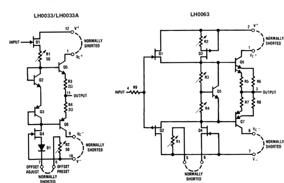
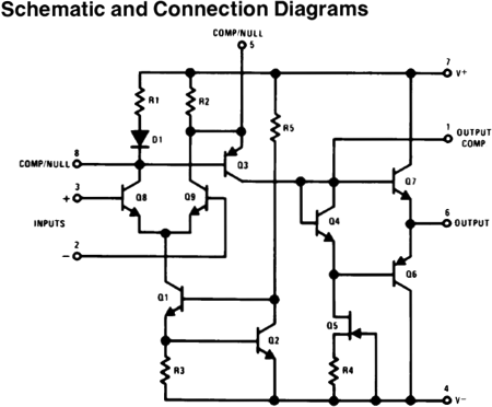
Designing with FETs When I was a young man, I was dazzled by the thick section of a National Semiconductor Linear Databook that was devoted to FET circuits. Then when they released their LH0033 and LH0063 unity-gain buffers that used FET input stages, I was amazed by the performance they achieved.
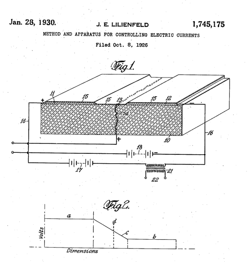
Look at the LH0063's schematic and explain why FETs Q3 and Q4 are there. My guess is that they allowed DC offset trimming through pins 5 and 6. Do I think that FETs sound tube like? My answer depends on the type of tube you have in mind. For example, I don't think that FETs sound that much like triodes, but I do think that they do sound like quiet pentodes. In addition, both the FET and pentode were invented in the same year, 1926. WTF! 1926? Yes, 1926. Julius E. Lilienfeld filed a patent in that year for the FET, titled, "Method and Apparatus for Controlling Electric Currents."
I love history in general, but I particularly love "What If" history, historical analysis that asks what if. What if Christ had died of old age rather than on the cross? Pontius Pilate could have decided differently. What if Hernán Cortés had lost his first battle in the Americas? Has any general ever been more lucky than he? Speaking of the Americas, what if the Chinese had discovered it first? What if Winston Churchill had died in 1931, when he was hit by a car in New York City? Sprechen Sie deutsch? If he had died then and if you live in Europe, you probably would—and possibly, eventually, we all would. I bet you are guessing that I am about to mention what if solid-state development had taken off in 1926? What if Steve Jobs had still owned an iPod, but he had it as child and it was made by Western Electric? No, you guessed wrong. I am about to mention ancient Rome. About four hundred years after Christ, De rebus bellicis ("On the Things of Wars") was anonymously written. It put forth the radical suggestion that the Roman army should become mechanized. It was ignored; it was viewed as a silly idea, as why should anyone create machines when he has slaves? Paul Johnson in his book, Enemies of Society, argues that what killed Rome wasn't Christianity, decadence, tyranny, but slavery; Rome choked on slavery just as slavery had choked off the middle class, and with them, the politic and economic freedoms that a strong middle class had required and created; an empire filled with plundered loot and slaves doesn't need a middle class.
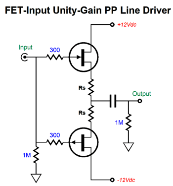
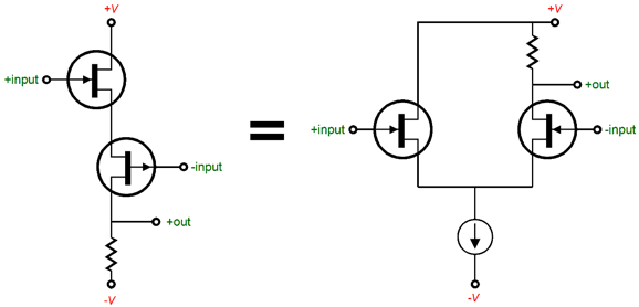
What if Rome had gone for a mechanized army and technological way of life? Perhaps, the Northern Barbarians would have faced bullets, not swords. And would we not have experienced a sixteen-hundred-year technological jump, so that J. S. Bach would have thought an iPod an interesting antique, but not something a serious music lover would own? Returning to FETs and FET-based circuits, although high-voltage FETs have been made, some with 300V breakdown voltages (I own fifteen 2N6449 300V N-channel FETs), most available FETs are low-voltage devices, sadly. Nonetheless, we can marry them to vacuum tubes and retain the benefits of both. FETs are, in general, much quieter than triodes. I remember the first time I build a circuit using the famous Toshiba FETs. I was sure that I hadn't attached my scope probe, as I saw a flat trace, not the outline of the Swiss Alps traces that I was used to seeing when working with tube circuits. And tubes, in spite of their glass envelopes, are amazingly sturdy in the face of high voltages. I own an HP voltage regulator that uses tube pass devices and I am too embarrassed to admit how many times that I have shorted its output—and the dang thing just keep on going. Solid-state gear is simply not as forgiving. Of course, if you don't have to deal with high voltages, then the FET's low-voltage operation becomes a feature, not a liability. One nice feature the FET offers over the transistor is that source biasing allows us to create circuits such as the following.
Two FETs, six resistors, one coupling capacitor—that is all that is needed to make push-pull, unity-gain buffer. Doing the same with transistors would require many more parts. Replacing the top N-channel FET with a triode would not increase the part count.
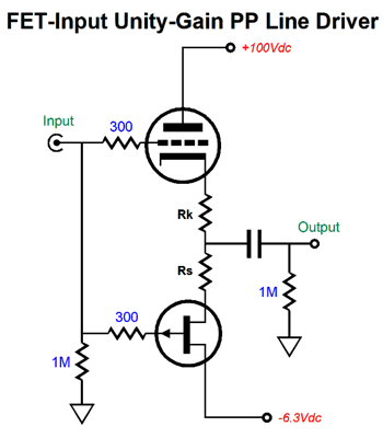
The negative power-supply rail could be used to power the triode's heater. If more current is needed, we could place-several P-channel FETs in parallel, each getting its own source resistor, while the solo triode would get a single cathode resistor. Of course, getting just the right resistor values might prove difficult or result in too large of values; for example, for an idle current of 10mA, the triode might require a 10V cathode voltage, while the FET might require -1V source voltage, making a voltage span of 13V. A total of 1300 ohms of resistance is not not to find, but it mean a higher output impedance than we might desire. The workaround is to let the cathode drive the FET's gate in the somersault topology.
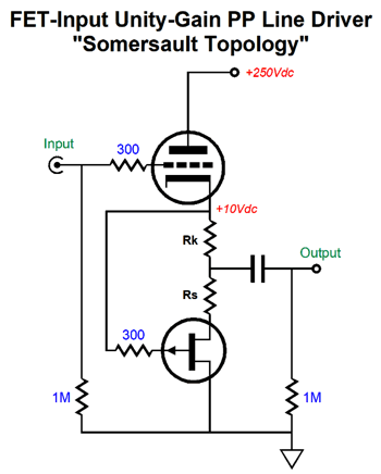
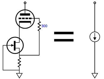
Note that we lost the negative power-supply rail, which is a plus. Moreover, we can use much smaller valued bias resistors. Ideally, we want to achieve balanced push-pull operation between the triode and the FET, so mismatched bias resistors are likely, say 24 and 75 ohm resistors. (Effectively, the FET and the two resistors define a constant-current source, the combined 99-ohms of resistance allowing the FET to idle at 10mA.) How do we find the right balance between resistor values? The quick and dirty way is to do so mathematically by looking up the transconductance values for the triode and FET, and then portion out the values to establish equality. The problem, or rather the dirty part, here is that data-sheet transconductance values tend to be wildly optimistic and may not apply at the desired plate voltage or idle current. In SPICE simulations, we place current meters in series with the FET's drain and the triode's plate, and then view the anti-phase current swings. In reality, we can use a distortion analyzer or FFT to evaluate the balance, as the prominent distortion harmonic will be the second; and the lower the second harmonic, the better the balance. Because this configuration results in a class-A, push-pull operation, we can expect to get up to twice the idle current as the peak current swing into the external load impedance. Amazing, what we can do with so few parts. In fact, a single FET and one resistor makes a constant-current source. Indeed, we could even lose the source resistor. Making a high-voltage constant-current source, however, would require cascoding the FET with either a high-voltage MOSFET or transistor or tube.
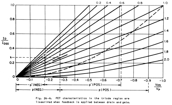
A triode's plate impedance is equal to its plate resistance (rp) added to (mu + 1)Rk. Since the FET presents a near infinite drain impedance, the triode's plate impedance will get even closer to infinity. Or does it? FETs have a "triode region" of operation, wherein they exhibit drain resistance, much as a triode exhibits plate resistance. The following graph shows a P-channel FET's triode region.
I have often wondered how a FET that was designed to offer a fat, wide triode region of operation would perform in audio circuits. Would it be like a small, solid-state version of the triode. We did once have such a beast in the gridistor, which was FET that was physically made as analogy of a triode, as the gate was made of an array of evenly spaced round rods, which resulted in triode-like drain curves. Unfortunately this device was developed when the world thought the pentode a marvelous advance over the triode, so the gridister was deemed a step backwards, not forwards.
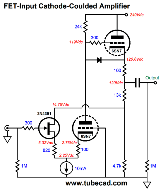
FET Cathode-Coupled Amplifier
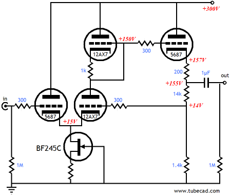
We sneakily steal some of the voltage from the cathode follower. The result is that 5mA flows from the FET and 3mA flows from the 4.7k resistor. This amplifier stage delivers low distortion and a low output impedance, but it does not deliver a stellar PSRR figure, as it achieves only -4.6dB of PSSR. I cannot let this stand, so I applied some Aikido mojo and the PSRR now approaches -60dB.
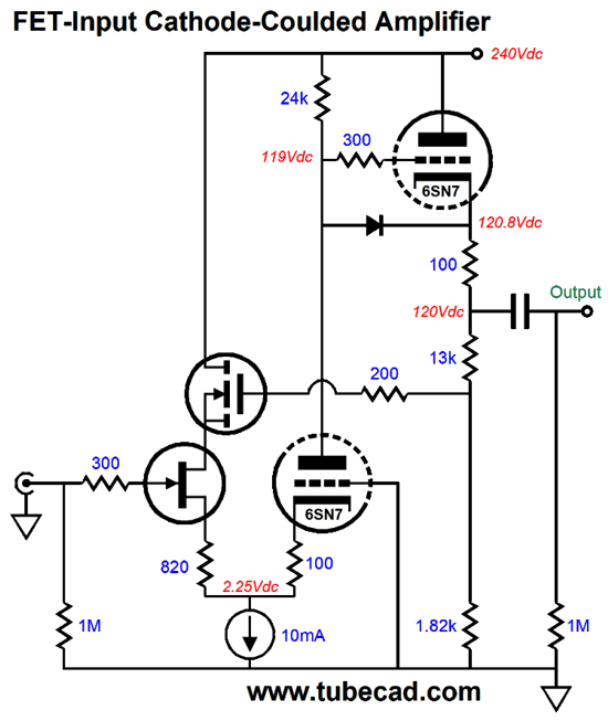
An alternative workaround would have been to place a high-voltage MOSFET or another triode in series with the FET's drain.
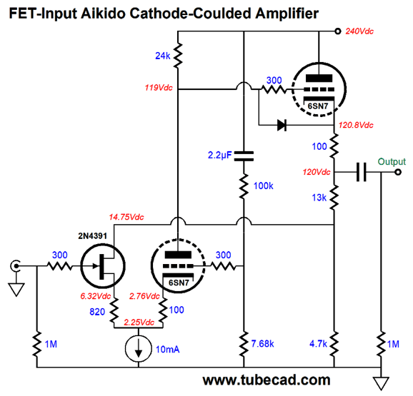
In both cases, the FET's drain sees a portion of the output signal, which is in phase with the input signal. Thus, if we fiddle with the part values, we can end up with same signal at the FET's drain as there is at its gate, which will result in even lower input capacitance. What happens at startup, when the triodes are cold and not conducting current? Nothing much. The diode becomes forward biased and conducts, so the FET still sees some drain voltage.
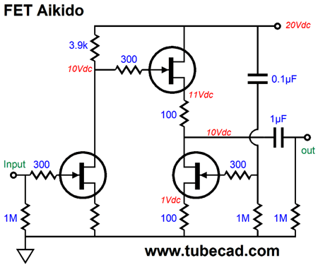
FET Aikido
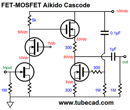
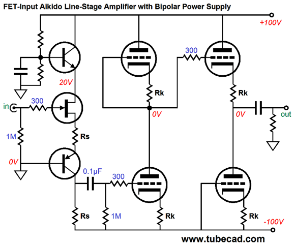
If more gain is needed, we need only bypass the input stage's source resistor with a large-valued capacitor, while the rest of the circuit remains unaltered. By the way, we could use all P-channel FETs and a negative power-supply rail. Why? Think about it: we could then DC couple a triode's grid to the FET Aikido stage. If bigger output voltage swings are needed, we can use a blend of FET and MOSFETs.
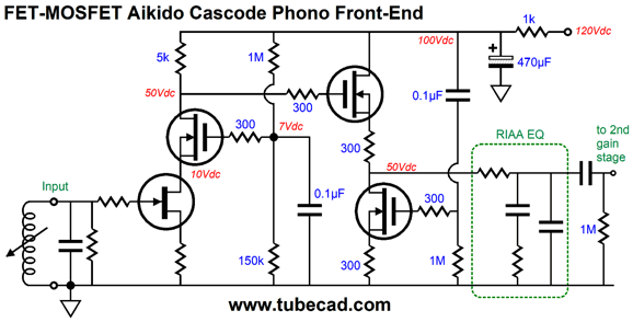
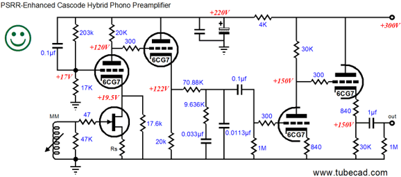
This is a real cascode circuit that uses depletion-mode MOSFETs rather than the typical enhancement-mode MOSFETs. One example is the IXCY 10M45S, which is sold as a variable constant-current source. With a 300-ohm source resistor, the 10M45S idles at 10mA. As the 10M45S is rated for 450V, we could easily up the B+ voltage to 300Vdc and use a 15k drain resistor in the first stage. Like the all-FET version, all of the power-supply noise is relayed to the bottom 10M45S gate. The following is one possible use for the circuit: a phono stage.
The input stage's source resistor could/should be bypassed by a large-valued capacitor. Passive RIAA equalization is used and the second stage could mimic the first.
FET Cascodes
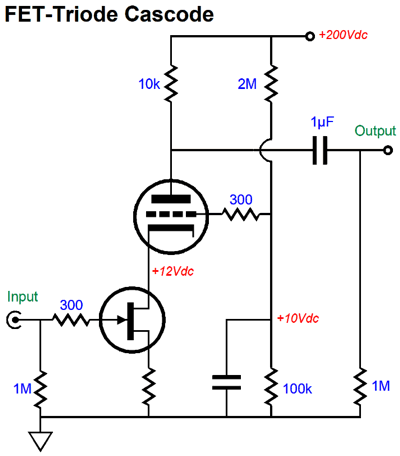
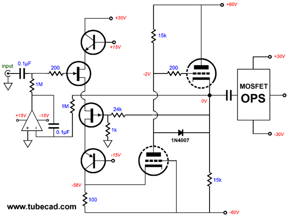
The triode's cathode shields the FET from the high B+ voltage and the FET offers high transconductance and low-noise gain. Since this circuit yields virtually no PSRR, we could follow it with an Aikido cathode follower (ACF), as it would scrub away the power-supply noise from its output. Less obvious is the FET-triode cascade, not cascode topology.
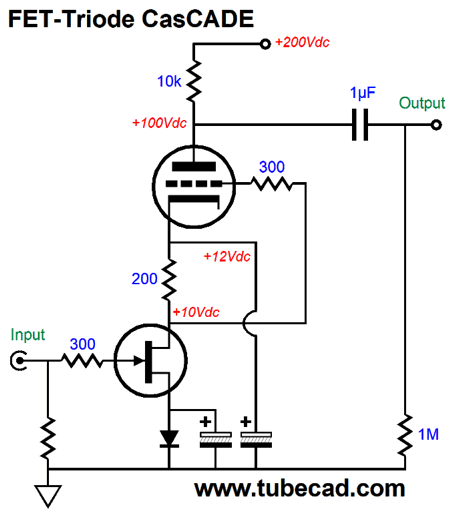
I have shown this topology before, but I bet it still looks weird to many long-time readers. What is going on is that the FET is configured as a grounded-source amplifier, whose output is DC coupled to the triode above, which is configured as a grounded-cathode amplifier. A cascade of amplifiers, in other words. Note the large-valued capacitor that shunts the triode's cathode to ground. This capacitor allows the two cascaded amplifiers to work in anti-current phase, unlike a cascode, which hold only one AC signal current path. In other words, when the FET stage draws more current, the triode stage above it draws less. This diphasic conduction only applies to AC signals, as only one DC current path from ground to B+ voltage exists. Also note the diode being used in place of a source resistor for the FET. The assumption here is that the 0.7V voltage drop across the diode is equal to what the FET requires to bias up correctly. If more source voltage is needed, we can double up on the diodes, placing two in series. Or, we could do something altogether different.
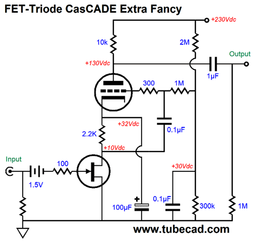
No source resistor is used, just a direct grounding of the FET's source, with a battery providing the needed negative bias voltage. Yes, changing batteries is a pain, but with a shelf life almost a decade long, most audiophiles have only changes left in their remaining years. In other words, the battery is not actually powering anything, so it does not get used up, rather it fades away. (It can be bypassed by a high-quality film or PIO capacitor.) In addition, the FET amplifier stage is no longer DC coupled to the triode amplifier stage. Why not? By using an internal coupling capacitor we can use a much larger drain resistor on the FET stage, allowing much more gain to be developed.
FET-Based Bastode Circuits
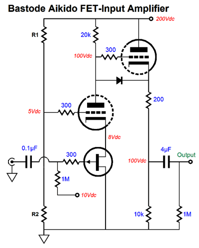
Since FETs also come in a P-channel version, we can make a bastode circuit with a triode and a FET.
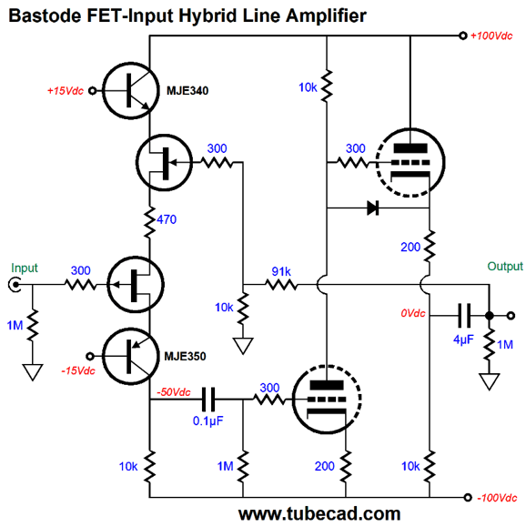
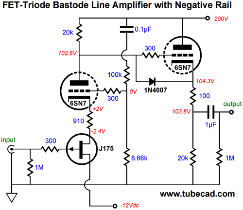
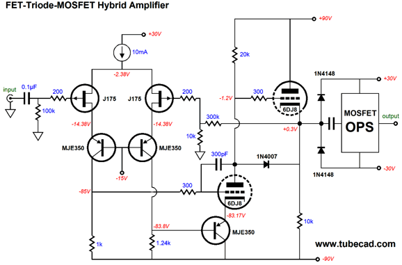
The above circuit might appear complex, but it is simply a cathode follower tagged onto a FET-triode bastode stage. I could not resist adding some Aikido mojo, so the PSRR is substantially improved. The P-channel FET's source directly attaches to the triode's cathode. This amplifier circuit does not invert the input signal phase at the output. This means that we could use the triode atop the FET as an inverting input, so a negative feedback loop could be made. If nothing else, some form of DC negative feedback will probably be needed to keep the desired idle current flow through the first stage maintained. The following circuit uses two FETs to create a bastode stage that is then further cascoded.
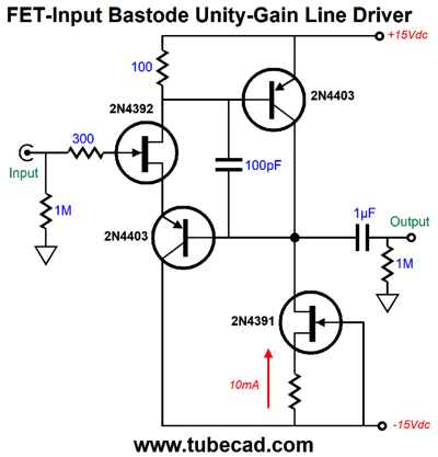
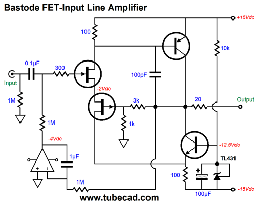
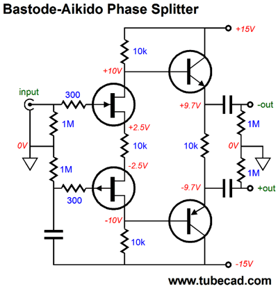
The NPN and PNP transistors protect the two FETs by creating a low-voltage window to work within. The MJE350 transistor allows the variation in current flow to travel down and through the 10k collector resistor. The two FETs share a common source 470-ohm resistor, which divided into the 10k collector resistor gives us our first approximation of the the input stage gain. The second stage is a grounded-cathode amplifier that creates a power-supply noise null at its plate, as it splits the two anti-phase bipolar power supply rail noises, resulting in a null, as +1 and -1 equals o. If the two power-supply rails do not hold equal, but anti-phase ripple, this deal is off. The last stage is simply a cathode follower, which offers a low output impedance. Why add the extra 200-ohm cathode resistor? Two reasons: the first is that helps prevent the cathode follower from leaking power-supply noise at its output, as we want this cathode resistor and the triode to define an impedance equal to the 10k cathode resistor; the second reason is that cathode follower work best—when driving capacitance—in a non-naked fashion. Of course, we do not have to use any tubes. The following bastode circuit runs off low-voltage power-supply rails
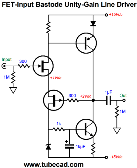
The 2N4392 input FET's source is tied to PNP transistor's emitter, making the transistor's base function as an inverting input, so we can apply 100% negative feedback from the output, making this a unity-gain buffer, not an amplifier. The 100pF capacitor helps prevent high-frequency instability. Since FETs cost much more than transistors, we can replace the FET-based constant-current source with a transistor-based one.
A few extras got thrown in here (I am sneaky that way). the zener is used to establish a reference voltage for the transistor-based constant-current source. The diode was added to allow a larger-valued drain resistor to be used, which will increase the open-loop gain, resulting in more negative feedback and lower distortion and output impedance. I know that many will be offend by the coupling capacitor at the output. Well, we can use a DC servo to eliminate it.
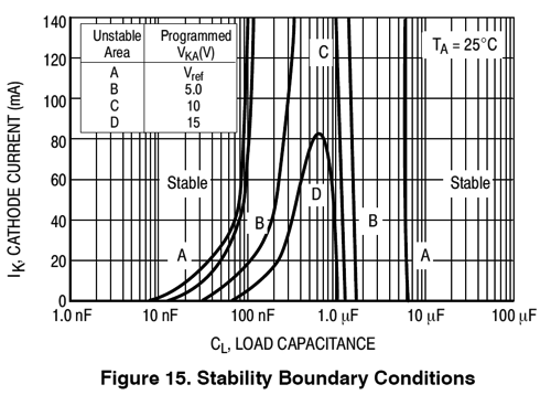
If the output drifts away from 0Vdc, the OpAmp's output will slide its output voltage in the opposite polarity until 0Vdc is reestablished. The TL431 is used to voltage reference the 2N4401 NPN transistor. The 100µF bypass capacitor was not arbitrarily chosen, as a band of capacitance must be avoided when bypassing the TL431 shunt voltage reference.
Note that a 0.68µF bypass capacitor will result in instability, while a 6.8nF or 68µF will prove stable. If we wish to get extra fancy, we replace the single-ended output stage with a push-pull one.
The above is not a buffer, but an amplifier, which provides a gain of +12dB (X4). The 20-ohm output resistor was added to shield the output stage from shorts or excessive capacitance. The push-pull operation obtains from the input stage P-channel FET's drain no longer terminating into the negative power-supply rail, but the 100-ohm emitter resistor. This arrangement confuses many, so do not feel bad if you cannot make sense of it. Two current paths flow out of the 100-ohm resistor, one path is up through the NPN transistor's emitter, while the other is up through the P-channel FET's drain. Either the FET or the transistor can provide 100% of the current flow or some ratio can be divided between them. Let's assume equal current sharing. If the FET draws 1mA more of current, then the transistor must draw 1mA less current, as a fixed voltage drop exists across the 100-ohm resistor, which implies a fixed current flow. While the FET is drawing more current, so, too, is the PNP transistor at the top, as its base sees a bigger voltage. Thus, while the NPN draws less current, the PNP draws more; while the NPN draws more current, the PNP draws less; push-pull operation in a nutshell. This scheme shows in in many OpAmps; for example, the LH0024's Q3 is setup this way, so that both its base and emitter get driven by the differential input stage (Q8 & Q9).
This OpAmp boasted some amazing specifications for 1995, such as a slew-rate of 500V/µS and small signal bandwidth out to 70MHz. Not bad for such a simple circuit.
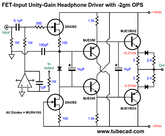
FET Headphone Drivers
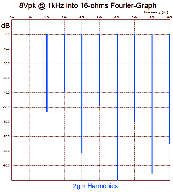
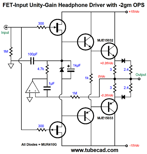
The FET-based input stage is pure single-ended, with a FET-based source follower loaded by a constant-current source. The transistor-based output stage is a modified diamond stage. The modification stems from the inclusion of the rectifier between the MJE350 and MJE340 bases and the rectifiers at the very output. The result is a constant-transconductance output stage. As it stands, the MJE15032 and MJE15033 draw 90mA of idle current, which dang healthy, and which ensures up to 180mA of peak current into the external load while still in the class-A envelope. This is enough to produce 500mW into a 32-ohm load. Once we leave the class-A window of operation, i.e. when either the MJE15032 and MJE15033 cutoff, the opposing rectifier begins to conduct, which will effectively double the "on" transistor's transconductance. Does it really make a difference? Oh yes indeed. Here is the SPICE-generated graph of the circuit with the anti-2gm rectifiers and resistor 2.4-ohm resistors.
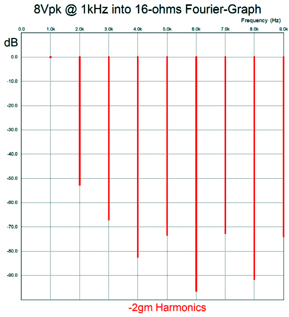
Not bad at all. Now here the graph of the same circuit without the anti-2gm extras.
Typical class-AB, push-pull output stage, jagged, with spiky odd harmonics. Note that the 3rd harmonic is almost 30dB higher that the THD is a tad over 1%, while the -2gm version offered only 0.25% of THD. Mind you, THD is not nearly as important as the harmonic structure. We can go for the full complementary topology by replacing the FET-based constant-current source with a P-channel FET.
The diamond configuration has been replaced by a more conventional dual emitter-follower setup. The zener establishes the output stage idle current and it can be replaced the more conventional Vbe-multiplier circuit. In a typical high-quality transistor class-AB output stage, 0.22-ohm emitter resistors are used and 118mA of idle current flows, resulting in just 26Mv of voltage drop across each emitter resistor, not the 260mV in the anti-2gm output stage. This tenfold increase in voltage allows for a lot more latitude, so the zener might work just fine. The biggest change, in my opinion, is the DC servo, which no longer works at the FET bases, but the FET sources. I have used this type of tugging servo many times before, including inside triode circuits, but I seldom, if ever, see it used elsewhere. The idea behind this DC servo is that no input coupling capacitor is used; instead, the OpAmp monitors the DC offset at the buffer's output; and if it encounters a DC offset, it pulls the FET input stage up and down until the offset disappears. The conventional DC servo leads the input stage, while this one tugs. The assumption here is that the circuit would otherwise present a low DC offset, so the OpAmp can tug it back in line through the 4.7k resistor. Think of it a kinder, gentler DC servo. Of course, if the input signal contains a large DC offset, say due to a leaky coupling capacitor, then this servo is unlikely to work and a more aggressive DC servo is needed.
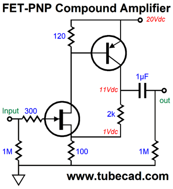
Super-Simple, Super-Fine FET Circuit
Two active devices, six resistors, and one coupling capacitor is all that is needed. The 100-ohm source resistor and the 2k collector resistor define a negative feedback loop and a load for the PNP transistor. The distortion signature is very single-ended and low.
PAST TCJ FET-Based Circuits
https://www.tubecad.com/2007/05/blog0105.htm
https://www.tubecad.com/2007/09/blog0119.htm
https://www.tubecad.com/2014/06/blog0294.htm
https://www.tubecad.com/2014/06/blog0297.htm
https://www.tubecad.com/2014/08/blog0302.htm
https://www.tubecad.com/2014/08/blog0303.htm
https://www.tubecad.com/2014/10/blog0309.htm
https://www.tubecad.com/2015/05/blog0322.htm
https://www.tubecad.com/2016/03/blog0341.htm
//JRB
User Guides for GlassWare Software
For those of you who still have old computers running Windows XP (32-bit) or any other Windows 32-bit OS, I have setup the download availability of my old old standards: Tube CAD, SE Amp CAD, and Audio Gadgets. The downloads are at the GlassWare-Yahoo store and the price is only $9.95 for each program. http://glass-ware.stores.yahoo.net/adsoffromgla.html So many have asked that I had to do it. WARNING: THESE THREE PROGRAMS WILL NOT RUN UNDER VISTA 64-Bit or WINDOWS 7 & 8 or any other 64-bit OS. I do plan on remaking all of these programs into 64-bit versions, but it will be a huge ordeal, as programming requires vast chunks of noise-free time, something very rare with children running about. Ideally, I would love to come out with versions that run on iPads and Android-OS tablets.
//JRB
|
|
Kit User Guide PDFs
Only $12.95 TCJ My-Stock DB
Version 2 Improvements *User definable Download for www.glass-ware.com |
||


| www.tubecad.com Copyright © 1999-2017 GlassWare All Rights Reserved |