| John Broskie's Guide to Tube Circuit Analysis & Design |
28 August 2017 Post Number 393
Special Thanks If you have been reading my posts, you know that my lifetime goal is reaching post number one thousand. I have 607 more to go. With only eight more to go, I should easily be able to hit post 400 this year. My second goal is to gather 1,000 patrons. I have 950 patrons to go. If you enjoyed reading this post from me for the last 18 years, then you might consider becoming one of my patrons at Patreon.com. It would make a big difference to me. Thanks.
Bi-Wire Ideas If you haven't read my last post, you should read the last third of it to get got up the general idea of two-amplifier bi-wiring.
Before jumping into the power amplifier circuits, let's pause and consider the art and practice of bi-wiring, bi-wiring with one amplifier per channel. First of all, if you haven't tried it, you should, assuming that your speakers sport bi-wire terminals. Do not go out and buy an extra set of $30,000 speaker cables. Instead, disconnect one of your speakers and place the remaining speaker in the middle of the room and listen to some old mono jazz or blues or old mono Beatles tracks. Get a feel for mono; learn to hear what mono offers. I know that I have heard—and my friends tell me they have also heard—stereo imagining in mono systems. Before you scoff, try to remember that we neither see nor hear passively.
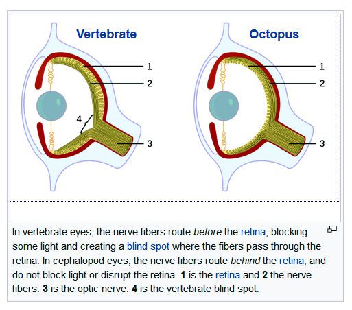
Our brains evolved to force sense and coherence on crappy perception. For example, each eye presents a big black spot in our field of vision that we never see, as our brain fills in the missing visual perception for us. Black spot, what black spot? That spot is also called the "blind point" and it refers to the blind portion in our visual field due to the absence of photoreceptor cells on our optic disc because the optic nerve must pass through the optic disc. A flaw that we do not see, as our brains interpolate the missing portions of our view and superimpose the brain-created image atop the black blur. The proof is offered by closing one eye and then having a doctor drop a powerful sedative in your open eye, which will prevent your eye from moving; as the eye stops moving the dark spot appears. move your head and the spot disappears; remain still, and it returns. In other words, our brains do photoshop tricks every waking second. The octopus has a superior designed eye, thus betraying its extraterrestrial origin no doubt ;) as Wikipedia explains:
If we ever achieve advanced bio engineering, this is the eye that people in the future will have. Returning to hearing imaging in mono playback, if you have sat before many orchestras, your brain will memorize where the horns and cellos are located. Just as the eyes and brain work hard to convince us that we see a seamless world, our ears and brain work to convince us that a real sounding world blares before us. In other words, what we see and hear is not identical to what enters our eyes and ears. Think about this: what percentage of a beloved's beauty is really only the beauty projected by the lover upon his beloved rather than the actual beauty beheld? (In 1822, the French writer, Stendhal, wrote an interesting book, titled De L'Amour. In this work, he explains his theory of crystallization, which explains how we fall in love; in short, we fool ourselves. The Spanish philosopher, José Ortega y Gasset, rebuked Stendhal in Ortega's posthumous 1957 book, On Love, wherein Ortega points out that Stendhal theory better explains how we fall out of love than how we fall in love. By the way, love at first sight is a predominately male emotional response, which might partially explain why male audiophiles outnumber female audiophiles twenty to one.) I have read of interesting experiments in hypnosis; for example, a subject is told a post hypnotic suggestion that when he awakens he will not be able to see the salt shaker on the table before him. He awakes and he cannot see it; it's just not there —for a while at least, then his head begins to hurt, then he sees the salt shaker. I am convinced that this explains listener fatigue, that tired, headache-making feeling after a few hours of serious stereo-system listening. Think about it: we listen to what is really wretched noise coming out of our speakers that only vaguely resembles a 100-piece orchestra, but our brains forces the sonic image of the orchestra—until the brain wearies, our head hurts, and the illusion is broken. Perhaps, for this reason, listening to mono is less fatiguing—at least for me. In fact, there are times when I can only hear nakedly, without my brain's heavy-handed sonic overlay, when I stand in a doorway or another room and where no chance for stereo imaging exists.
Okay, I admit this was a long side-trip, but we now return to bi-wiring. After you have gotten used to one speaker, which will probably sound a bit thin at first, you take the unused speaker cable and use it to bi-wire your single speaker. Try it. If you like what you hear, then you buy another pair of $30,000 speaker cables. Or, should you? Maybe you should buy a different $30,000 set of cables. Conceptually, it seems to make sense that the cable best suited for bass playback is not likely to be the best suited for high-frequency playback, so shouldn't you purposely use two different types of speaker cable? I love the theory, but hate the practice. In general, I have found the results usually worse than using just one cable and no bi-wiring. The one exception I have encountered was when I was going through my thin, solid-core wire phase (after I had read about what Denis Morecroft was doing in England; by the way, I believe that he is far more right than he is wrong and I remain a big fan of his efforts).
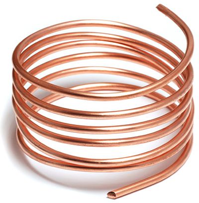
I loved much of what I heard with skinny solid-core wire, but not everything. As a compromise, I used 12-gauge magnet wire for the woofer and 22-gauge wire for the tweeter: differing-gauge bi-wiring, in other words. How did it sound? I thought it sounded great, but then I wanted it to sound great. One crazy thought I had was that since I was padding the tweeter's output with a -3dB two-resistor attenuator, why not just use a speaker wire with enough resistance to achieve the same amount of attenuation? With an 8-ohm tweeter, 3.3-ohms of resistance would be needed. Now, 10 feet of 30-gauge wire presents 1-ohm of resistance and 30-gauge is dang skinny. I discovered that 10 feet of 35-gauge wire would give me 3.29 ohms; the only problem was finding 35-gauge wire; I never did. See post 242 for more speaker cable stories from me.
Active Bi-Wiring Ideas
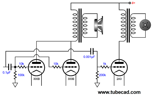
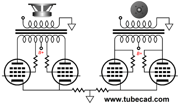
These two output transformers do not differ in power output, but do differ in low-frequency extension. The output transformer on the right goes down to 30Hz at full power; the one on the left, 100Hz. I hold to a strong prejudice that small output transformers, in general, sound better than big output transformers. Indeed, I would love to have custom made single-ended output transformers (air-gapped) that could sustain 150mA of primary current and only go down to 400Hz, These would prove ideal in bi-amp and bi-wire systems. Perhaps, you have seen the power transformers that were used in airplanes that were designed for 400Hz, not 60Hz use. They are tiny, but powerful. Do not forget David.
Now, imagine two 300B output tubes in parallel single-ended for the woofer and one 2A3 for the tweeter. What about the power mismatch, as the 300B tubes would yield close to 20W, while the 2A3 would deliver only 2.5W?
Let's start with the tweeter; 2.5W into 8 ohms equals a peak voltage swing of 6.32V. In contrast, 20W into 8 ohms equals 17.9Vpk. In terms of decibels, the 20W is 9dB more signal. Well, if the tweeter is 9dB more efficient than the woofer, say 94dB versus 85dB, then both wattages would effectively equal. If the tweeter were a horn-loaded design with an SPL of 111dB, then the woofer's amplifier would have to put 160W to match the 2.5W amplifier's output into the tweeter. (Well, at least that is what my quick calculations tell me.) The two single-ended output stages could share the same input stage and power supply. in other words, three transformers, one power and two output, and three output tubes on one chassis.
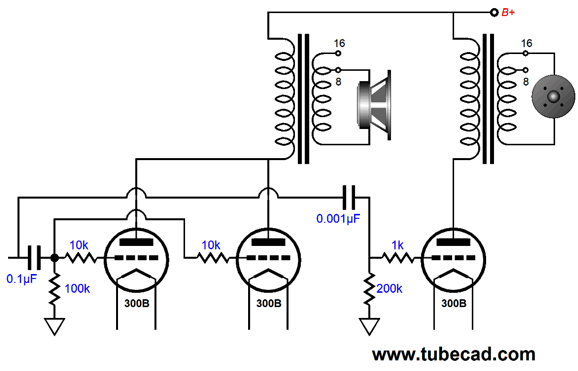
This setup might sound great, but then it violates the vertical bi-amp rule, which states the same amplifiers and the same cabling should be used throughout, rather than risk sonic discontinuities. I happen to respect this rule, as I have heard many smorgasbord bi-amped and tri-amped systems that sound fractured and disjointed. Okay, we could use three identical output tubes and two identical output transformers. The woofer would get two output tubes in parallel, while the tweeter gets one. How is that possible, won't the impedances be all wrong? The workaround is not to use the same output taps. For example, if the transformer's primary impedance is 5k and the woofer's impedance is 8 ohms, we would attach the woofer across the 8-ohm and ground taps. If the tweeter was also 8 ohms, we would attach it across the 16-ohm and ground taps, as that would ensure that each output tube would see the same 2.5k load impedance. Or, we could attach the woofer to the 4-ohm and ground taps and attach the tweeter across the 8-ohm and ground taps, which will result in the same load impedance for each output tube, but at half the previous value.
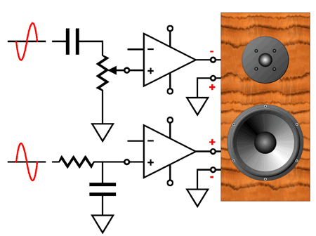
Wait a minute, John, you said that the tweeter is often far more efficient than the woofer, so why are you giving it more output voltage? Good question; I am glad you asked it. True enough, tweeters are in general far more efficient, and thus they need to see less voltage, not more than the woofer. Inside your speaker, you will undoubtedly find two power resistors that are used to pad the tweeter, which reduces the voltage the tweeter sees. In contrast, I would much prefer to use a volume control to reduce the amplifiers output, rather than throw away power in padding resistors. The sneaky part is where we place the volume control.
Note that both output stages share the same coupling capacitor, but the output stage amplifier receives less input signal than the woofer output stage. A similar setup is possible with push-pull output stages.
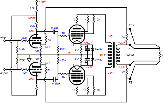
Note that each output stage uses the same number of output tubes, two, but that output tubes are differently configured. The woofer output stage uses its two pentodes configured in the ultra-linear fashion, while the tweeter output stage uses triode-connected pentodes. Of course, what I had in mind here was taking a preexisting tube push-pull power amplifier, such as the famous Dynaco ST-70, and using one per speaker. In this scheme, each output stage gets its own input stage. I would use a negative feedback loop on the woofer output stage. (See post numbers 183 & 184 which explain remote feedback sensing.) And I would let the triode-based tweeter output stage run feedback free.
In my last post, I mentioned the stacking of two Advent speakers that a friend of mine had set up, using the bottom identical speaker as a subwoofer. I was so impressed with the sonic clean-up that resulted that I have never forgotten my smile upon hearing it play. Well, what if we did the same, i. e. stack two identical speakers, but raise the crossover frequency to the geometric mean frequency. Given the frequency bandwidth of 20Hz to 320Hz, the geometric mean frequency would be 80Hz, as 20Hz doubles twice to get to 80Hz, while 80Hz doubles twice to get to 320Hz. Fmean = √(F1 x F2) We find the geometric mean frequency by taking the square-root of the product of the lowest frequency against the highest frequency reproduced. For example, given 20Hz and 20 kHz, the geometric mean frequency would be 632Hz. If the low-frequency cutoff were higher, say 50Hz, then the geometric mean frequency would be 1 kHz. I would love to re-hear the stacked Advent speakers with an active 632Hz crossover, the bottom speaker driven by the ultra-linear power amplifier and the top speaker driven by the triode-connected amplifier. Because the two speakers are identical, they share identical frequency responses and phase aberrations, and because the 632Hz frequency presents so large a wavelength, the two speakers would meld easily, sounding like one cleaner-sounding speaker. Why cleaner sounding? The top speaker's woofer will not have to move so far back and forth, as it wouldn't be required to reproduce low frequencies, which means that frequency-modulation distortion will be substantially reduced.
Since tube power amplifiers, even old Dynaco ST-70 amplifiers, cost a lot what about adding a tiny class-D amplifier for powering the woofers and using the tube power amplifier for the tweeters. The class-D amplifier would easily fit within a thin sub chassis that the tube power amplifier would sit atop. The slim bottom chassis could also hold a high-quality RFI filter that would feed the tube amplifier its AC. In this way, only one power switch need be flipped at turn-on. By the way, when I say tweeter amplifier, I only mean the amplifier that powers the high-frequency speakers, which could be a full-range driver or a mini monitor or a fairly large satellite speaker; and the "woofer" speaker could be another full-range driver or 5-inch woofer or huge subwoofer. Let's assume subwoofer and satellite speakers. The slender bottom chassis would make an interesting high-end product, as it could incorporate electronic crossovers and the RFI filtering and two 500W class-D power amplifiers in a 1-inch tall chassis. One supreme advantage, at least in my mind, to this arrangement is that when it is too late at night or too early in the morning for subwoofer thumping, the bottom chassis could hold a defeat switch which would turn off the sub amplifier and restore full bandwidth to the tube amplifier. As the TV commercial used to sing, "Sometimes you feel like a nut, sometimes you don't."
Air-Core Output Transformer Failing this, I have re-stacked push-pull output transformers in order to make them single-ended designs. All the "I" and "E" laminations are stacked into two piles, then a thin strip of gasket material is place in between the stacks of iron laminations and the bell caps and screws are put in place. Well, while performing one of these transformer transformations, I decided to measure the inductance of the wire bobbin without its core. Surprisingly high, I thought at the time, not enough for full bandwidth, but plenty for a super-tweeter amplifier. For example, if X amount of inductance is needed to provide bandwidth down to 20Hz, then only one tenth of X will be needed to go down to 200Hz, and only one hundredth to go down to 2kHz. In fact, I have wanted to try to incorporate the air-core transformer inside the output transformer's housing (think potted box). In other words, the two output transformer windings, each holding the same winding ratio, would be wired in parallel to each other.
I should mention that many will argue that something like this already occurs in output transformers, as the iron core cannot respond to high-frequencies so the primary and secondary form an air-core transformer anyway. Possibly, probably, but my guess is that this occurs at a much higher frequency. With two wire bobbins, we could force a lower transition frequency. How? By adding a simple two-way crossover within the potted transformer box.
The capacitor would prove very small in value. For example, a 2500-ohm primary crossing over at 5kHz would need only a 0.013µF capacitor. The iron-core primary would need an 80mH inductor, which would be partially made up from leakage inductance. Indeed, we could place the crossover frequency up at 30 kHz, far beyond the CD's 22kHz limit, but where many output transformer start to poop out. An alternative crossover arrangement is shown below, which allows current flow through the air-core output transformer.
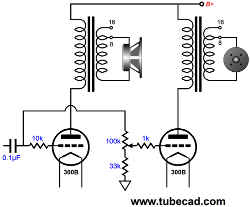
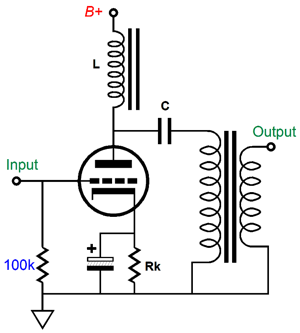
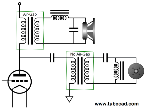
So far, this two-way output transformer has nothing to do with bi-wiring. Bi-wiring, however, adds extra complexity, complexity that we can exploit. First, let's review the para-feed output stage configuration.
The inductor provides a DC current path for the output tube and the coupling capacitor prevents DC current flow into the output transformer, which means that no air-gap is required and we can use a nickel-core output transformer. Well, what if we use the woofer's output transformer as an inductor at high-frequencies?
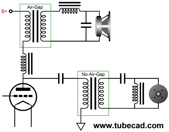
At high-frequencies, due to the woofer's own passive crossover, the woofer output transformer becomes unloaded, making it into an inductor. We could help things along by adding an inductor to either the secondary or primary, as we want the output transformers bandwidth to overlap at the speaker's own internal crossover frequency. For example, if the speaker crossovers at 3kHz, then the tweeter output transformer should go down to 750Hz, two octaves lower in other words, while the woofer's transformer should go out to 12kHz, once again, two octaves. Assuming a 3K primary output transformer, a 40mH inductor would be needed in series with the primary. In contrast, a 0.1mH inductor would be needed on the secondary. The problem with adding the inductor to the secondary is that each 16-ohm, 8-ohm, and 4-ohm output tap would need its own inductor.
An iron-core inductor is shown, as an air-core 80mH inductor, even one wound with thin wire, would be huge.
Solid-state Bi-Wire Ideas
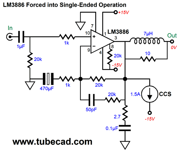
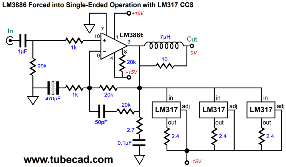
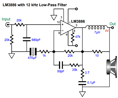
A simpler approach would be to limit the power-supply rail voltages and just use a constant-current source to force single-ended operation on the chip amplifier.
Note the wimpy +/-15Vdc power-supply rails. The most we could hope for would be 12Vpk of output swing, which translates into 9W into 8-ohm loads. Since 12Vpk divided by 8 ohms equals 1.5A that is how much current the constant-current source must draw. In this setup, both the LM3386 and constant-current source will dissipate 22.5W, making a total of 45W per channel. That is a lot of heat to wick away. If we adopt my own 60-degree centigrade temperature limit for the heatsinks, and assuming an ambient temperature of 25C, then a heatsink with a thermal resistance of only 0.77C/W will be required per channel. The constant-current source can be made from discrete parts or several LM317 three-pin voltage regulators could be used instead.
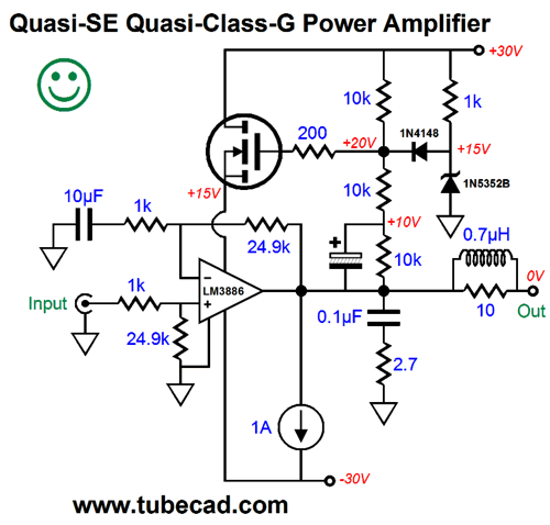
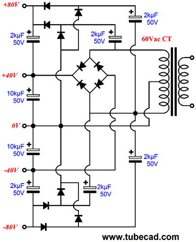
Now, 9W may not sound like a lot of power, although it will have 2A3-based flea-power amplifier owners drooling with envy, but it would prove sufficient to drive a high efficiency tweeter to screaming SPLs. Here is an example, given a woofer with an efficiency of 88dB, quite common, and a tweeter with an efficiency of 94dB, also quite common, the woofer amplifier would have to be four times more powerful to match the SPL output of the tweeter; in other words, 9W and 32W. This makes for simple math, as twice the peak output voltage is required for four times the output wattage. Since we specified 15V power-supply rails, the woofer amplifier will need 30V power-supply rails instead. Two-to-one is a good ratio, as we can easily derive +/-30V and +/-15V power-supply rails from one center-tapped 24Vac primary. The following schematic shows +/-80V and +/-40V power-supply rail voltages, but the topology remains constant; we need only alter the capacitor voltages and transformer secondary voltage.
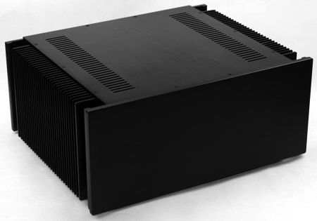
Of course, two transformers could be used instead, considering the cost and size of large-valued power-supply reservoir capacitors. I would use one amplifier chassis per channel. For relatively little money, we can buy from Chinese sources empty power amplifier chassis. They usually come with pre-cut holes for one power receptacle, two RCA jacks, and four output terminals, which would come in handy in this application.
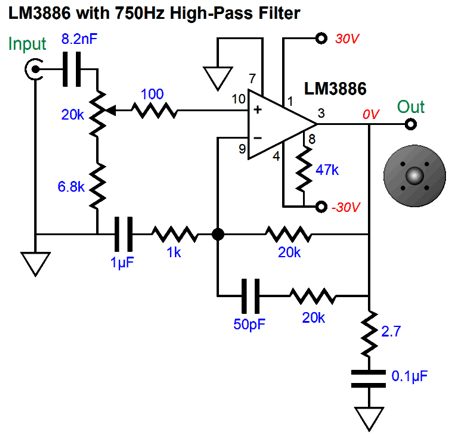
Adding the high-pass frequency filter and volume control for the tweeter amplifier is easy enough.
Note that the signal attenuator is part of the high-pass filter. Because the tweeter amplifier need only extend down to 750Hz or so, the terminating capacitor at the end of its negative feedback resistors can be a relatively small-valued film capacitor. With the woofer amplifier, which need only extend out to 12 kHz or so, we can use a larger valued negative feedback compensation capacitor.
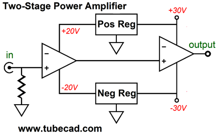
Okay, what about those situations where we dare not open up a $20,000 two-way speaker to remove the tweeter's padding resistor network? I feel your unease at the thought. In this case we could run both amplifiers without any attenuation on the tweeter amplifier or we could try something different. For example, we could use two gainclone power amplifier for the high-frequency outputs and two non-bridged class-D power amplifiers for the low-frequency outputs. All four power amplifiers would fit in a standard amplifier chassis. Of course, if you can afford $20,000 two-way speakers, why bother with gainclone power amplifiers? Perhaps, my old approach for using two cascading amplifiers, each with its own negative feedback loop could be used, but with the variation of using two second stages.
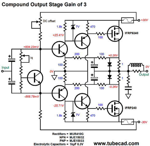
One possible idea might be to build a discrete solid-state power amplifier that holds two output stages, one filled with four cheap IRF HEX MOSFETs and one filled with two expensive lateral MOSFETs. What follows is a schematic for a compound amplifier that consists of just two stages, an input and output stage. The AC gain is set by the 100-ohm and 200-ohm resistors, resulting in a gain of 3; the DC gain is 4.
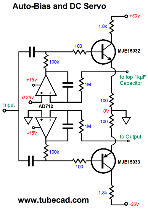
The two diodes work as zener diodes of sort, as they are not forward biased at idle, but once the voltage across the 1-ohm drain resistors exceeds 0.52V, the conduct. This serves two purposes: it prevent too large a voltage drop across the drain resistors, thus increasing potential power output; and this voltage limit prevents the two capacitors in the feedback loop from over charging, as the idle voltage drop across the resistors is set to one half diode's break voltage. Note that two negative feedback loops are used to establish the desired DC voltages, but the two capacitors AC couple the amplifier's output to each 200-ohm feedback resistor. We can get extra fancy here, as the diodes also allow the use of auto-bias circuitry.
Bear in mind, that lateral MOSFETs must see a much lower source-to-gate voltage, which will mean less open-loop gain, as smaller-valued collector resistors must be used. The input stage could be made from a high-quality OpAmp, while the woofer output stage would use the cheap IRF MOSFET, while the tweeter output stage would use lateral MOSFETs. As you can see, the possibilities are truly numerous, and we are only limited by our imaginations and wallet.
//JRB
Post Script
Yes, it is entirely in French. While I cannot read French novels, I can read French electronic books. Well, in this fantastic little book, we find so many gems. For example, here is an ultra-high-gain differential amplifier that can achieve a gain of 200,000!
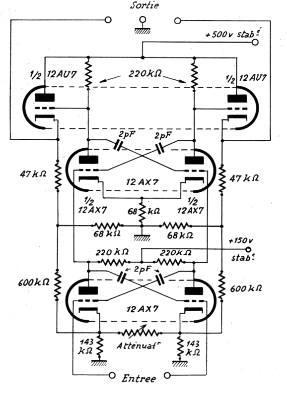
Two 12AX7 and one 12AU7 tubes make the lineup, the 12AU7s acting as cathode followers, the 12AX7s cascading grounded-K amplifiers. Okay, if your mind isn't blown, it should be. Let's start with its gain of 200,000. How is that possible? The square root of 200,000 is 447, which means that each 12AX7 would have to have an amplification factor at least equal to this number. The tube manual states 100 as the 12AX7's mu, which squared equals only 10,000, one twentieth of the 200,000. In fact, most current-production 12AX7 are hard pressed to achieve a mu of 95. So, where did all the extra gain come from? Answer: positive feedback. Note where the cathode follower's load resistors terminate.
If you enjoyed reading this post from me, then you might consider becoming one of my patrons at Patreon.com.
User Guides for GlassWare Software
For those of you who still have old computers running Windows XP (32-bit) or any other Windows 32-bit OS, I have setup the download availability of my old old standards: Tube CAD, SE Amp CAD, and Audio Gadgets. The downloads are at the GlassWare-Yahoo store and the price is only $9.95 for each program. http://glass-ware.stores.yahoo.net/adsoffromgla.html So many have asked that I had to do it. WARNING: THESE THREE PROGRAMS WILL NOT RUN UNDER VISTA 64-Bit or WINDOWS 7 & 8 or any other 64-bit OS. I do plan on remaking all of these programs into 64-bit versions, but it will be a huge ordeal, as programming requires vast chunks of noise-free time, something very rare with children running about. Ideally, I would love to come out with versions that run on iPads and Android-OS tablets. //JRB |
E-mail from GlassWare Customers
High-quality, double-sided, extra thick, 2-oz traces, plated-through holes, dual sets of resistor pads and pads for two coupling capacitors. Stereo and mono, octal and 9-pin printed circuit boards available.
http://glass-ware.stores.yahoo.net/ Support the Tube CAD Journal & get an extremely powerful push-pull tube-amplifier simulator for TCJ Push-Pull Calculator
TCJ PPC Version 2 Improvements Rebuilt simulation engine *User definable
Download or CD ROM For more information, please visit our Web site : To purchase, please visit our Yahoo Store: |
|||


| www.tubecad.com Copyright © 1999-2017 GlassWare All Rights Reserved |