| John Broskie's Guide to Tube Circuit Analysis & Design |
|
06 October 2016
Differential Amplification of Unbalanced Inputs
In post number 355, I showed how a simple CCDA could be used with this arrangement. Well, the list of circuits that are useable doesn't end there, as many more topologies can be employed. How many? Many, indeed. I have used the gold miner metaphor many times before. I like it and I so weary of war metaphors. Just about all business operations, sporting events, and all modern political campaigns are invariably described as battles; indeed, the very word “campaign” comes from the Italian word for battlefield. How tiresome it is to hear or to read about war chests, battles and combat, strategies and tactics. Surely other metaphors could be applied, such as farming, with its cultivating, planting, and harvesting. Or, perhaps, fishing or weaving or woodworking could be used—anything but warfare.
Yet, in spite of my war-metaphor fatigue, I was about to use a Napoleonic-battle metaphor to describe how once I spot a new topological opening, I rush in to breach it. (I just remembered that I have used the “once more unto the breach” line from Henry V speech before; another war metaphor, alas.) So, instead, I will reuse the gold miner analogy: for once I catch a glimpse of a new topological possibility, I become like a gold miner, crazed and grisly, having spotted a thick vein of gold, as pages get filled in my sketchpad with new circuit schematics, until my imagination or wrist gives out, usually the latter.
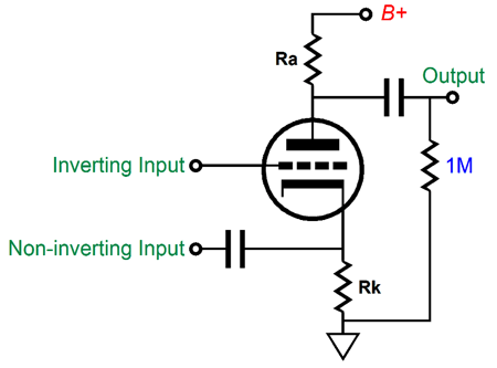
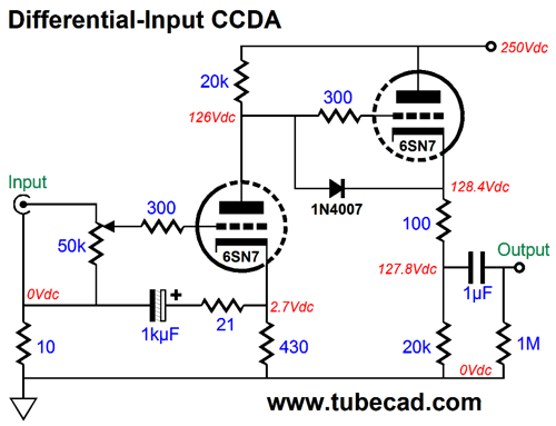
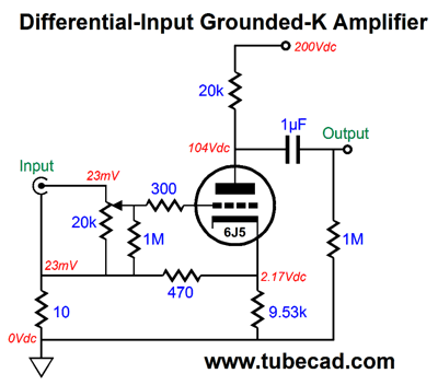
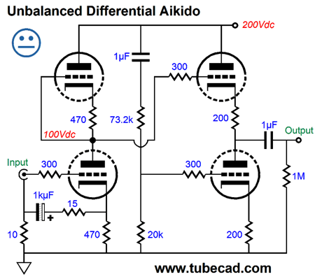
Since the first half of the constant-current-draw (CCDA) amplifier is simply a grounded-cathode amplifier, we already have that topology covered—or do we? No doubt that many will find the 1kF electrolytic capacitor icky in the extreme. Yet its inclusion seems essential, but is it? If we remove it, the 6SN7 sees an effective cathode resistor value of only 26 ohms (I bet you thought it was 31 ohms), far too low. Okay, but what if we also replace the 21-ohm resistor with a 470-ohm resistor?
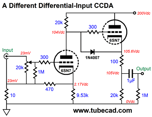
In SPICE simulation, a cathode resistor of 9.53k was found to be optimal, as it ensured a high common-mode rejection ratio (CMRR). Remember that the triode's cathode offer slightly higher gain than the grid does. Thus, the 470 and 9.53k resistors define a two-resistor voltage divider, which reduces the cathode's gain to that of the grid. (Do not forget that, in a grounded-cathode amplifier, the grid inverts, while the cathode maintains the phase of the input signal.) Note that the B+ voltage has dropped from 250V to 200V in the second schematic. Also note the addition of the 1M resistor after the volume potentiometer, which provides a path to "ground" should the volume control lose contact. Mind you, we can just as easily run a single triode in a ground-cathode amplifier circuit.
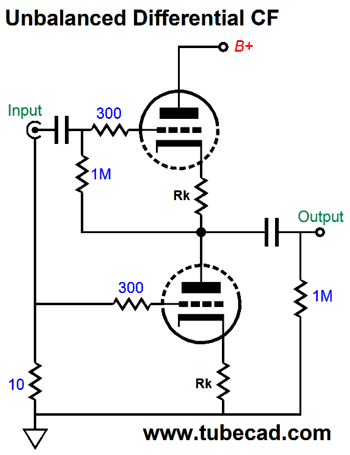
The 6J5 is a single-triode tube that is basically half a 6SN7. The 6J5G comes in the fancy bottle shape and cost much more than the 6J5GT. The 12J5 is the same single triode with a 12V heater element (AKA, VT-135) and supremely fine ones can be bought for $10 (or less). The output impedance of the above circuit would be about 10k, which may or may not be a problem. Since the first half of the Unbalancer Two is a vertical differential amplifier that doubles as a differential cathode follower of sorts, we also have a cathode follower with an active load that differentially accepts an unbalanced input signal.
Note how we do not have to worry about DC offsets or an input coupling capacitor for the bottom triode.
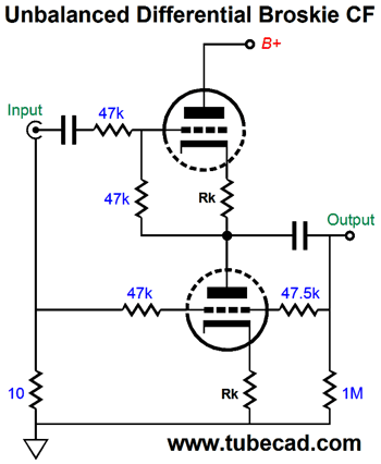
The Broskie cathode follower (BCF) comes gift wrapped for this new application, as it is a buffer that accepts a balanced pair of input signals and puts out an unbalanced output signal. Its arrangement of feedback resistors makes it load independent and ensures that both top and bottom triode contribute equally.
In SPICE simulations, the 47.5k feedback resistor was found to yield the best CMRR. Now we move on to the tube darling of the century, the SRPP.
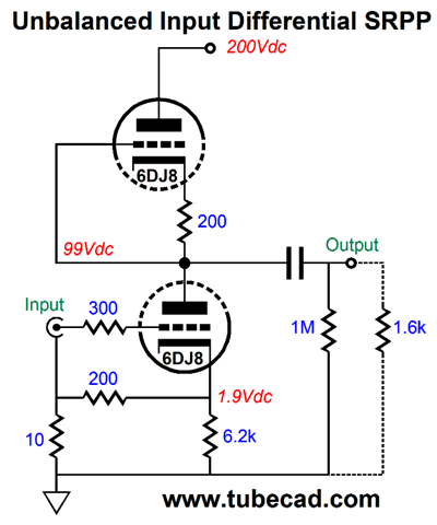
The SRPP is load sensitive, as it is a push-pull design and the load impedance is an essential part of the circuit. With the 6DJ8 tube, the 200-ohm cathode resistor, and the 200V B+ voltage, the optimal load impedance is 1600 ohms. If we do not need any extra gain, and if we can accept the balanced output, i.e. not grounded, then the SRCFPP can be used instead of the SRPP.
The tube type is not marked, but my SPICE simulations were run with these part values and a 6DJ8 and a B+ voltage of 200V. The SRCFPP, just like the SRPP (and White cathode follower, is load dependent; in this example, the optimal load impedance is 300 ohms. Since the bottom triode exhibited slightly greater transconductance than the top triode, the 180-ohm and 10k-ohm voltage divider was needed. Okay, what about our old friend, the Aikido amplifier?
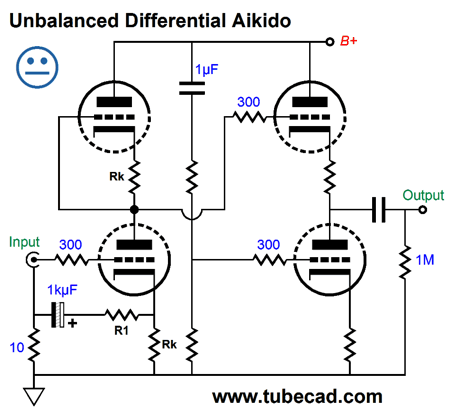
Once again, we could use an added small-valued resistor, R1, and a large-valued capacitor, as shown above. Here is the same circuit fleshed-out.
The neutral face denotes that although the circuit would work, many would prefer not to use an electrolytic capacitor. Well, let's not use one.
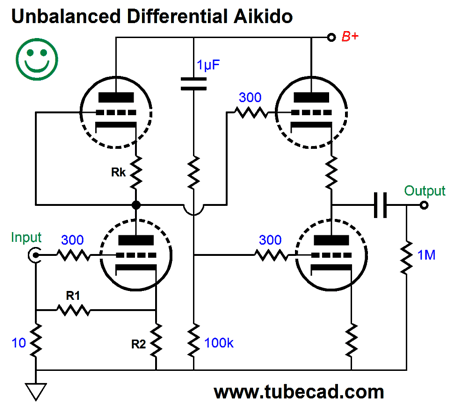
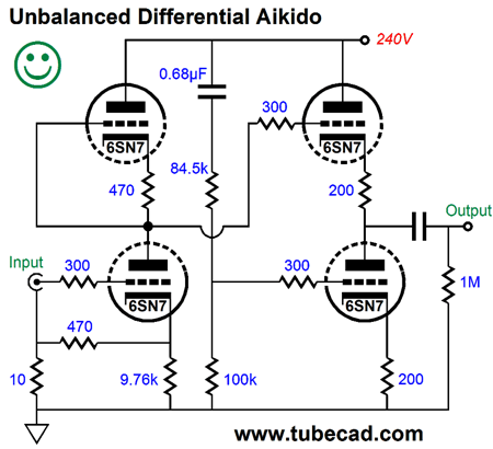
We have removed the capacitor, but we can no longer use a small-valued resistor for R1.
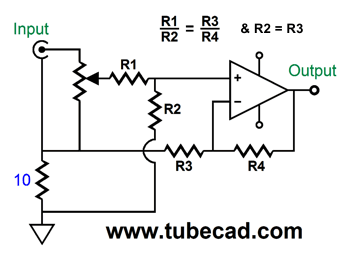
I should mention that amplifiers that hold a negative feedback loop present some issues that we must deal with. Since the inverting input offer less gain than the non-inverting input, we must burn off a little bit of the input signal that the non-inverting input sees. But how much? Easy answer, follow this ration between resistor pairs and all we will be well.
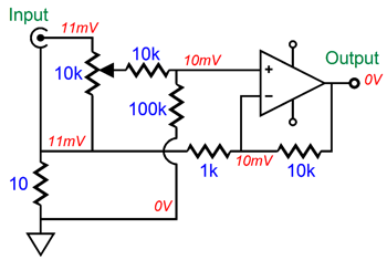
Here is an example with a DC offset present on the signal source.
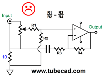
The matching resistor ratios ensures that the common (shared) DC voltage is ignored. Great, but what happens if the amplifier terminates its feedback resistor with a capacitor? No so great.
THe DC offset get pass on at the output, but at least it is not amplified. The workaround is to add a coupling capacitor.
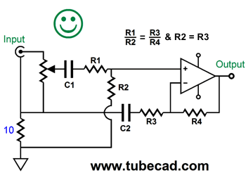
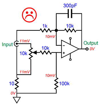
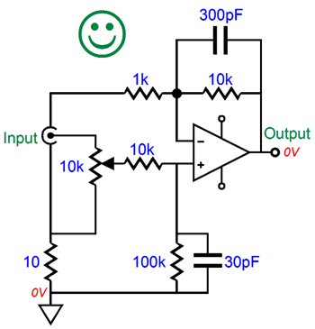
How big a coupling capacitor? Its value should ensure the same -3dB low-frequency cutoff frequency as the feedback coupling capacitor produces. What about the shunting capacitor that is often found across the negative-feedback resistor?
It must find a complementary shunting capacitor at the input.
Its time constant in parallel with its resistor must match the time constant that the feedback capacitor in parallel with its resistor produces. In the above example, 330pF shunts 10k, while 30pF shunts 100k, both result in low-pass transition frequency of 53kHz. Let's switch to a slightly different topic: differential (aka, bridge) power amplifiers.
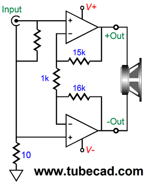
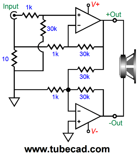
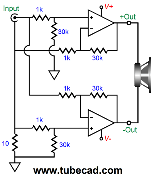
Differential-Bridge Power Amplifiers What follows is one way that we can make a differential/bridge power amplifier differentially accept an unbalanced input signal.
Note that the top amplifier uses a 15k negative feedback resistor, while the bottom amplifier uses a 16K resistor. Why the dissimilarity? The top amplifier is configured as a non-inverting amplifier, so its gain is equal to (15k + 1k)/1k, or 16. In contrast, the bottom amplifier is configured as an inverting amplifier, so its gain is equal to 16k/1k, or 16. If the signal source exhibits 1V of AC noise relative the the differential power amplifier's ground, then both the positive and negative outputs will present the same 1Vac in phase, so the speaker sees not differential AC signal across its resistance, so it produces no acoustic output. An alterative approach is the following configuration.
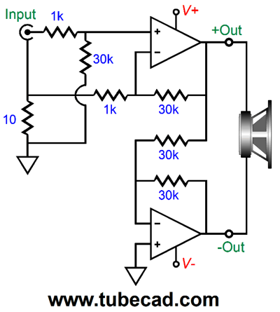
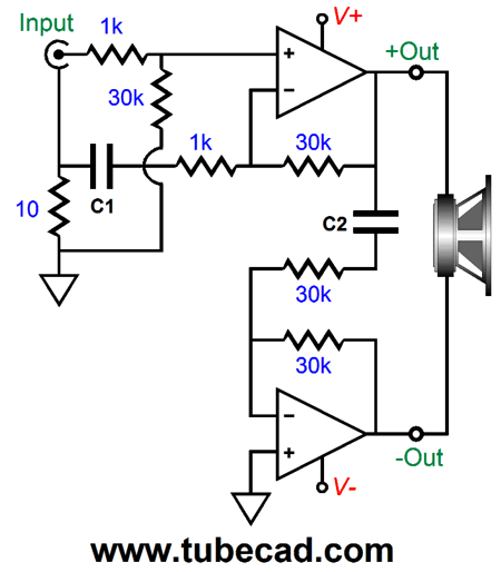
The top amplifier functions as a non-inverting amplifier, as before; and the bottom amplifier functions as a unity-gain amplifier, which means that we will likely run into phase-margin problems, which means that the popular LM3886 and other chip power amplifiers are not suitable; chip power amplifiers from Burr-Brown, however, could be used. The workaround is the following circuit.
The added 1k resistor bleeds off a bunch of potential feedback, which allows us to use a non-unity-gain-stable chip power amplifier. But let's ignore this potential problem and move on to DC offset elimination, which will require added capacitors, C1 & C2.
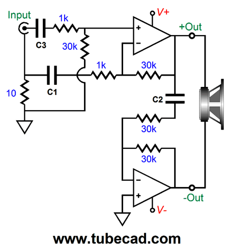
These added capacitors prevent the power amplifier's own intrinsic input DC offset from being amplified. But if the signal source itself presents a DC offset, then the following design is better, as the added input capacitor block the signal source's DC voltages.
Of course, the inclusion of any coupling capacitors is always a pain—and often an expensive pain. If the power amplifier's DC offset is low (or if it is adjustable), then the following version could be used.
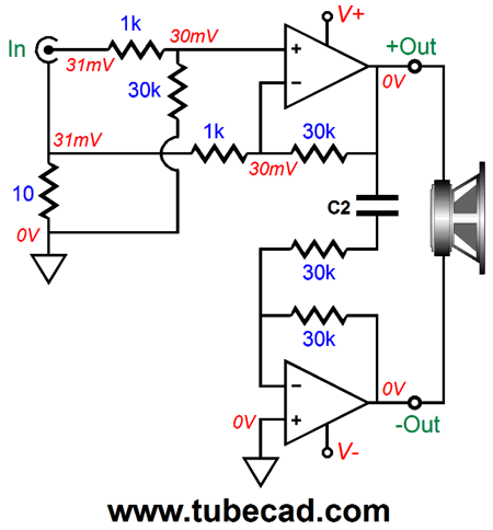
Remember that differential amplification not only applies to AC signals, but to DC signals as well. Since the signal source carries an equal DC offset on its ground and hot, the differential amplifier topology ignores the DC voltage. I cannot leave this topic without mentioning that a third differential/bridge amplifier topology, as shown below, which was borrowed from the TI application report SNAA021A; this PDF is well-worth reading, as it is filled with many interesting circuits and useful tips.
The top amplifier is configured as a non-inverting amplifier, while the bottom amplifier is configured as an inverting amplifier. Both exhibit the same gain and drive the speaker differentially. Well, can we alter the above schematic to force differential amplification of an unbalanced signal source? Would I ask, if I couldn't?
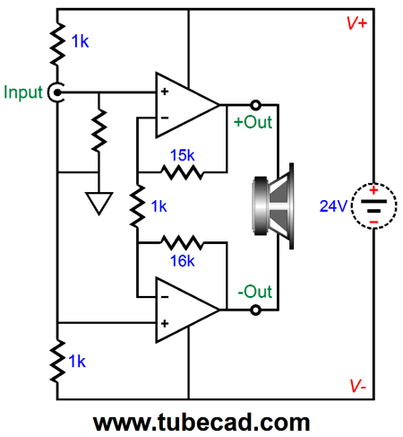
I left out the coupling capacitors for the sake of clarity, but they could (or should) be added. Let us now return to the first example of a differential/bridge power amplifier. One interesting application might to use a robust external switcher power supply, say a 24Vdc one.
The power supply is effectively a floating power supply—hence my symbol for floating power supplies—as neither terminal is directly grounded. The two 1k resistors in series span the 24V and define a 50% voltage divider, so the two amplifiers effectively see +/-12Vdc power-supply rail voltages. Even if four internal amplifiers were used, two per channel, the two channels would be wonderfully separated, as long as the two RCA jack ground lugs were not connected together through a common-ground wire. Of course, the two grounds would be directly connected together in the signal source, but that is what we want, as we want the two interconnects to contain each channel's AC signal in each channel's interconnect. If the amplifiers manage to differentially swing 20Vpk into an 8-oh, load, 25W of power would be delivered. Not bad from such a meager power-supply voltage. If a 48V switching power supply were used instead, then 40Vpk of voltage swing might be possible, which would yield 100W into 8-ohm loads. Mind you, the internal power amplifiers believe that that they are driving 4-ohm loads, not 8-ohm loads, so overheating could prove a problem with most chip amplifiers. The solution might be to double up the internal power amplifiers, so that four would be used per channel.
Unbalanced Differential Input Test
For example, if you swap in a different brand of coupling capacitors and replace the existing input tubes with another type, what can you conclude from your listening tests? Not much. If the resulting sound pleases or irks, which part change gets the credit? The coupling capacitors, the tubes, or both? Even if no sonic change is perceived, nothing of value can be deduced. How so? Three possibilities immediately come to mind: the new coupling capacitors and new tubes performed equally with the old coupling capacitors and tubes; or, the coupling capacitors were actually a bit worse than the capacitors they replaced, but the new tube type was so superior to the old type that it managed to undo the new coupling capacitor's failings; or, the new coupling capacitor revealed enough sonic subtleties to cancel out the extra drag imposed by a worse tube.
Even when we make only one change, we face the huge problem of elapsed time. For example, let's say that you wish to try a different output transformer, one with the same winding ratios as the existing transformer, but made by a different company. Assuming a stereo system, two transformers must be replaced. No matter how quick and skilled a solder slinger you are, such a project can take hours, if not a week to pull off. So, what does the elapsed time have to do with it? Unfortunately, everything. Our sonic memory is lamentably brief; some argue that it is measured in tens of seconds, not minutes, let alone hours or days. Moreover, our ears, like our eyes, are more sensitive to additions than to subtractions, errors of commission rather than omission, in other words. Our memory often fills in what our perceptions fail to reveal. Or as I put in post Number 165,
The secret to overcoming the time trap in sonic tests is to always use two otherwise identical line-stage amplifiers, phono stages, electronic crossovers, and power amplifiers, differing in only one part or part value or operating point or topology. Having two identical pieces of audio gear allows us to climb the ladder of sonic improvement. First we make sure that both stock units measure and sound exactly alike. Second, we make only one change to one of the identical units, leaving its former twin unaltered, before we hold a shootout. If the change was not step backwards, or what is much more common, a step sideways, but an actual sonic step forward, we then incorporate this change in the unmodified device. Then we begin again, until some change makes a further sonic improvement. Thus, we only move forward, and we do not take giant steps sideways. What if no change improves the sound? We were dang lucky and we should stop. Remember, our goal is to move only forward.* Well, at least that is the hope.
The actual act of hold a sonic shootout is not trouble-free, alas. I have found that the quicker the shootout, the more likely that the wrong conclusions will be reached, with the worse sounding change preferred. What! Here I quote myself quoting myself from post 181:
Well, in my recent experiment, I made many changes: I rewired my Reality-Check solid-state headphone amplifier to accept differentially the unbalanced input signal. Like a complete fool, however, I also went from metal-film to carbon-film resistors and used three different power supply capacitors. Five variables got changed, not one.
The result was indeed a sonic improvement. Great news, true enough. But which change made the biggest difference? Which change(s) hindered the forward movement? I cannot say, nor can anyone else. Worse, for me at least, conclusions that I had reached before from previous OpAmp shootouts no longer held.
I remember something like this happening when I and a group of friends held a three-bottle wine shootout. The Italian flag dish always gets big compliments; if nothing else, it was dang attractive. At the bottom of a large rectangular dish lies fettuccine noodles, which are covered in three stripes of sauce: green, white, and red. An editable Italian flag, in short. The green sauce was pesto; the white, Alfredo cream sauce; and the red, spaghetti marinara sauce. At this dinner party, we divided the work three ways: I brought my homemade pesto, while the two other couples brought the Alfredo and marinara sauces. Each couple also brought one $20 bottle of merlot wine.
Since this dinner party took place in California, all three men were budding wine snobs. I insisted on having the wine bottles brown bagged, which met much resistance, as most prefer to have a safety net in place before their taste buds (or ears) are put to the test. And, surely, the judges are judged as much as the items tested. For example, what if the same wine was poured into three glasses, but I thought they all tasted different? The horror. In this wine contest, all three men were in agreement—the women had no interest in the shootout, but did have great interest in actually drinking the wine— as all had ranked the three wines in the same order. Progress. As we were patting ourselves on our backs, the food was brought out. We brought our wine glasses with us and ate. I do not remember who said it first, but I know I was thinking it: the best wine was no longer the best tasting; indeed, the previously worst wine was now universally deemed the clear winner, while the middle wine remained in the middle, leaving the formerly best wine to fall to third place. The analogy I used that evening was that our wine shootout results were similar to us having evaluated bullets without having any gun to shoot them with, picking a winning bullet without actually firing it first. Something that we three men had apparently forgotten was that wine was made for the benefit of food, not the other way around. (Of course, another possibility was that the formally worst wine just needed more time to breathe, although an intensely tannic red wine might require something closer to a few hours to soften.)
What troubled me about my recent experiment was that my previously preferred dual OpAmp, the OPA2107, was no longer my clear preference with my Sennheiser HD650 headphones. I do not believe that reconfiguring the headphone amplifier to accept differentially the unbalanced input signal made the OPA2107 sound any worse, just the opposite.
My guess is that famous Burr-Brown mellowness and warmth which had proved a good complement to the metal-film resistors, whose colder, harder sound got softened and warmed by the OPA2107. But with the softer-sounding carbon-film resistors, the two cascading soft sounds rounded the sharp corners too much. In contrast, the harder-sounding Linear Technology OpAmps proved a better complement to the softer-sound resistors. I can, I freely admit, be totally wrong here. How so?
A total of five changes, including the resistors and the differential input. Any one change of any combination of changes could be the decisive change. With five variables, there are 120 possible configurations to test. With ten variables, we might as well give up, as none of us are likely to live long enough to perform exhaustive testing. As far as I am concerned, the real test of a headphone amplifier is how long do I want to listen to it. No matter how snappy, how exciting, how HiFi it sounds, if give up listening to it after only a few minutes, it is not a good headphone amplifier. Here is an example, a while back, I was searching through my collection of NOS tube for a pair of Telefunken smooth-plate 12A7/ECC83 tubes with the diamond bottom. In the box, I discovered that I owned two Telefunken 12AU7/ECC82 tubes. I immediately plugged them into one of my tube-based headphone amplifiers and prepared myself for sonic glory.
My disappointment was profound. No sparkle, no extended highs, no HiFi glory. Nonetheless, I couldn't stop listening. I wanted to, as I had lots to do, but I couldn't. I kept digging through my music collection, playing track after track. Over an hour later, I finally managed to break free from its spell. My view is that we are shockingly complex creatures. Part of our brain longs for sparkle, extended highs, HiFi glory, while another part longs for emotional connection. For me, I enjoy being dazzled once a year by watching a firework display; on a daily basis, however, I prefer the cheerful company of a dog.
Next Time
* I was once asked by a tube-audio company if they could send me their premiere preamp to see if I could make it sound more in line with its $4,000 price tag, a goal of which it it sadly fell short. I explained that I actually would need two units, so I could climb the ladder of sonic glory. No way. Apparently, I didn't comprehend the implicit deal, as their unstated assumption was that I would get to keep the preamp after I had modified it; but giving me two $4,000 preamps was just too expensive a transaction, no matter how good the results might be. (Mind you, a $4,000 only costs $1,000 in parts.) Of course, it is possible that they only had one actually-built preamp available. More likely, they didn't get how one did climb a ladder of sonic improvement.
User Guides for GlassWare Software
For those of you who still have old computers running Windows XP (32-bit) or any other Windows 32-bit OS, I have setup the download availability of my old old standards: Tube CAD, SE Amp CAD, and Audio Gadgets. The downloads are at the GlassWare-Yahoo store and the price is only $9.95 for each program. http://glass-ware.stores.yahoo.net/adsoffromgla.html So many have asked that I had to do it. WARNING: THESE THREE PROGRAMS WILL NOT RUN UNDER VISTA 64-Bit or WINDOWS 7 & 8 or any other 64-bit OS. I do plan on remaking all of these programs into 64-bit versions, but it will be a huge ordeal, as programming requires vast chunks of noise-free time, something very rare with children running about. Ideally, I would love to come out with versions that run on iPads and Android-OS tablets.
//JRB
|
|
Kit User Guide PDFs
Only $12.95 TCJ My-Stock DB
Version 2 Improvements *User definable Download or CD ROM www.glass-ware.com |
||


| www.tubecad.com Copyright © 1999-2016 GlassWare All Rights Reserved |