| John Broskie's Guide to Tube Circuit Analysis & Design |
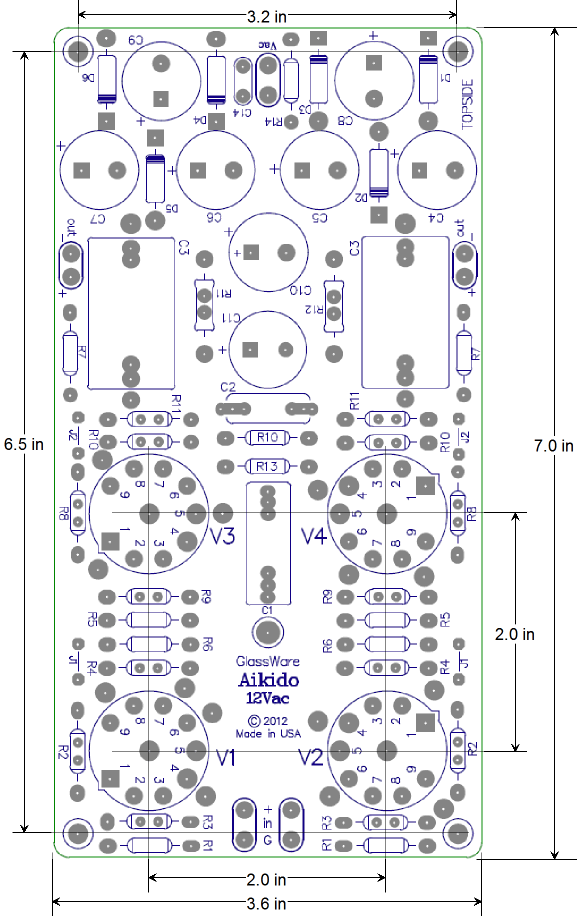
30 March 2013  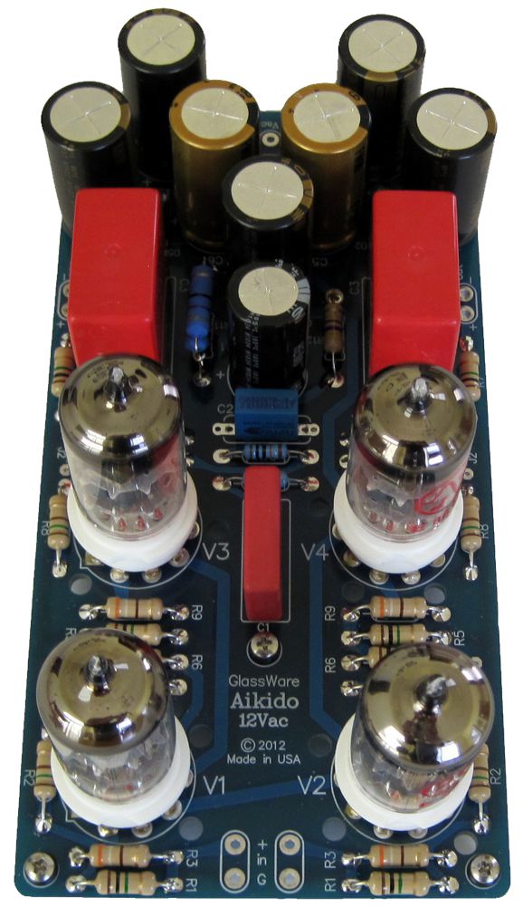 New Aikido 12Vac PCB Why yet another Aikido PCB? A very good question that deserves a very good answer. I know that many customers are using four 6DJ8 tubes with the Aikido LV PCB and a 24Vdc power supply, as they write me to tell me about how great their Aikido sounds. Well, here is the thing: I have tried using 6DJ8 with 24Vdc and they sound so much worse than the 6GM8 tubes in the same circuit that I would never recommend the pairing. Yes, yes, I know that their setups my indeed sound much better than their previous solid-state or tube line stage. The solution is more B+ voltage. But how do we retain the advantages of low-voltage and still get a decent B+ voltage? Well, the Aikido 12Vac is my solution, as the key advantage of the Aikido 12Vac is that it can be operated from a lowly wallwart power supply, yet develop a fairly high-voltage B+ for the triodes. Where the typical tube-based line-stage amplifier requires a B+ of 200V to 400V, the Aikido 12Vac can get by with only a B+ voltage of 80Vdc with 6DJ8/6922/E88CC tubes; or 120Vdc with 12AU7/ECC82/ECC802 tubes. The heaters are all placed in series and this heater string is powered by a portion of the the B+ power-supply voltage, the center third. Thus, a wallart's low-voltage AC from is all that is required to power the Aikido 12Vac.
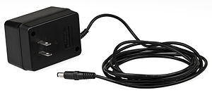
The power supply is internal to the 12Vac Aikido PCB and receives its power from an external transformer, usually a 12Vac wallwart. The 12Vac voltage runs through an elaborate sextupler circuit that develops both a high-voltage B+ and a DC heater voltage. If you guessed that 12Vac became 72Vdc, you missed by 1.414 times, which is the square root of 2. A 12Vac sine-wave actually peaks almost 17Vpk, so the actual DC voltage developed is equal to 6 x (12 x v2 – Vrect), where Vrect is the rectifier’s voltage drop. In other words, the sextupler creates a raw DC voltage of about 92Vdc.
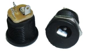
!!! IMPORTANT: If a metal power jack is used to receive the AC voltage from the wallwart's power plug, it must be fully insulated, as the incoming AC voltage is referenced to half the raw B+ voltage. In other words, the plug's outer barrel must not be grounded.
Note how the power-connecter jack is all metal, so I had to insulate it from the chassis with a nylon shoulder washer. Of course, the easier way to go is to use an insulated power jack.
If an 18Vac input voltage is used, a raw DC voltage of about 148Vdc is created. The 92Vdc voltage is perfect for use with four 6DJ8 tubes; the 148Vdc, with four 12AU7 tubes. The 12Vac transformer used with 6DJ8 tubes must provide at least 1.5A of current, which equals a VA rating of 18; the 18Vac transformer used with 12AU7 tubes must provide at least 1A of current, which equals a VA rating of 18. Ideally, a transformer with a good regulation figure (say the 5% to 10% a good toroidal transformer would offer) would be used; this is unlikely to true of a wallwart transformer, however, so some adjustment of the RC filter resistor values (R11 & R12) might be needed. The heaters must not see an over voltage, as such a voltage will greatly shorten the tube’s life.
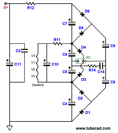
The raw high-voltage is cleaned up by an RC filter made up of R12 and C11 in parallel with C2. The four tube heaters are in series with each other and get their own RC filter made up of R11 and C10. Resistor R14 and capacitor C14 define a snubber circuit for any RFI that might be present on the incoming AC voltage.
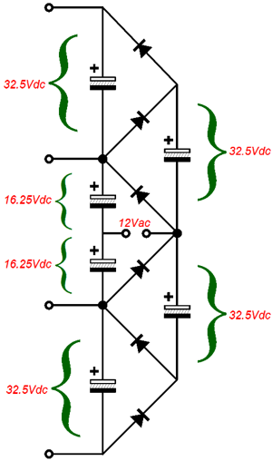
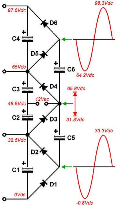
Voltage Sextupler Circuit Below we see the voltage relationships that develop from the 12Vac voltage.
The secret to understanding how this circuit works is to realize that the two rightmost capacitors bounce up and down due to the 12Vac voltage swings, while the four stacked capacitors on the left remain locked in place, in terms of voltage. Next, realize that as each of the six rectifiers becomes forward biased, it begins to conduct, which charges the capacitors.
Remember that capacitors C5 & C6 charge up to 32.5V each, so when the nexus between them swings down to 31.8V, the bottom stator of C5 becomes slightly negative relative to C1's bottom stator, causing the bottommost rectifier to become forward biased, allowing it to conduct.
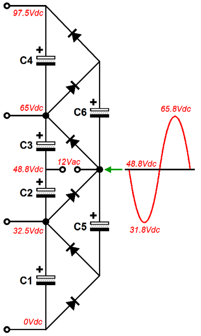
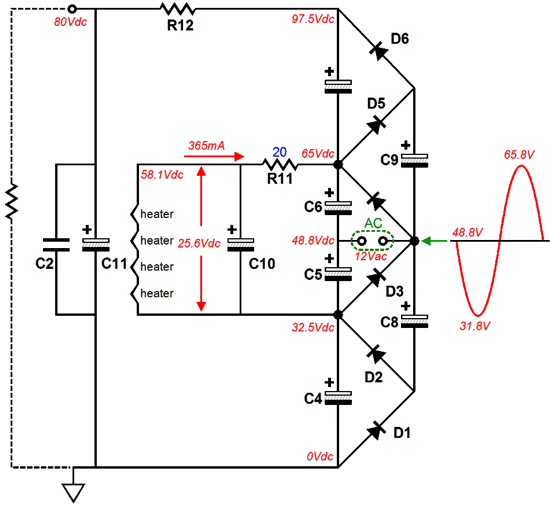
And when capacitor C6's top stator swings up to 98.3V, rectifier D6 becomes forward biased and conducts, allowing C6's charge to flow into C4. Now, let's look at the complete power supply circuit with the heaters in place. The assumption is that four 6DJ8 tubes will be used.
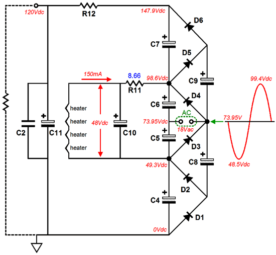
Note how all four tube's heaters are all in series and how the heater string is referenced to 32.5V above ground level. Also note how the resistor R11 drops about 7V, so the heater string sees 25.2Vdc. This resistor also prevents huge current inrushes at start-up, when the heaters are cold and, as a result, offer little resistance; this resistor will extend the tube’s life. Resistor R12 and capacitor C11 (in parallel with C2) define an RC filter for the B+ voltage the tubes will see. If 12AU7 tubes are used, an 18Vac wallwart will be needed and the following voltage relationships will result.
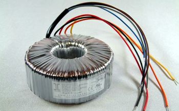
Note how each 12AU7 only gets 12Vdc across its heater element. If a 20Vac wallwart could be found, then more heater voltage would be available. But, in fact, a 18Vac wallwart will probably suffice. Such transformers offer very poor regulation, which means that their unloaded voltage is much greater than their loaded voltage. For example, unloaded, the 18Vac wallwart might put out 23Vac. So, if we use an 18Vac wallwart that is just a tad over specified in VA for this task, we will get enough raw heater voltage to give each heater 12.6Vdc. Speaking of wallwarts, AKA wall adaptors, Jameco Electronics sells an 18Vac @2.2A wallwart for only $8.95; and a 12Vac @1.5A wallwart that offers a accuracy figure of 5% and a regualation figure of 14.8%. They also sell a 13.5Vac @5A desktop enclosed transformer for only $16.95. Lest anyone believe that I am getting a kickback from Jameco, here is a link to Parts Express who are blowing out a desktop 12Vac @3.5A transformer for only $5.80. In the review section, we learn that the enclosure holds a 500mA fuse, which is a nice touch. The alternative to the wallwart is to use a transformer, such as a frame or toroidal or R-core type, in the same enclosure that houses the Aikido 12Vac (or in its own small external enclosure). One example is the Triad Magnetics VPT12-2080 toroidal power transformer, which puts out 12Vac CT @ 2.08A and which Mouser sells for $19.68.
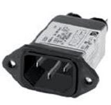
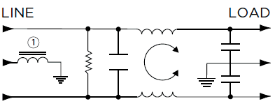
This toroidal transformer is only 71mm fat and 32mm tall, so it would fit in many small extruded aluminum enclosures. In addition, using such a transformer would allow to add all the extras, such as an EMI power inlet filter:
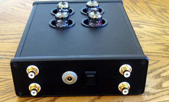
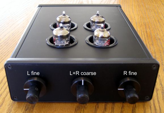
My Own Aikido 12Vac Line Stage The Aikido circuit delivers roughly a gain equal to half of the mu (amplification factor) of the triode used. With four 6DJ8 tubes (all the tubes must share the same heater voltage and heater current draw), the signal gain equals about 16 or +15dB; with four 12AU7 tubes, 8 or +9dB. This may not seem like much gain, but it is plenty for line-stage use, as most power amplifier require only 1Vpk to be brought to full output. If more gain were required, then a 12AX7-12AU7 or 12AT7-12AU7 combination would yield a gain of 50 and 30 respectively. In my own Aikido 12Vac, I used four JJ 6DJ8 tubes, which provided more gain than I needed and sound surprisingly smooth for a modern 6DJ8.
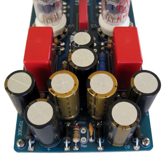
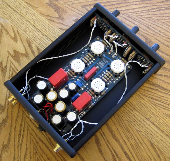
I used a Hammond Manufacturing1455T2201BK extruded enclosure with metal end-caps, which is only 8.66 x 6.3 x 2.03 inches big. When I bought the case, it cost $27, but its current price is $30.18 from Mouser (next yer, $33???). As you can see from the photo below, there's plenty of room for an A3-Mini stereo stepped attenuator (even with the large 1W resistors) and the Aikido 12Vac board. Mind you, I did have to use shorter hex standoffs. Drilling the the front an rear panels was a breeze, as the metal is thin. But punching the top removable panel was work, as it is so thick. Nonetheless, it was one of the easiest projects that I ever put together. And it sounds quite good. All the Aikido magic is there and it is amazingly quiet.
The Aikido 12Vac stereo boards and part kits are available now at the GlassWare/yahoo store for ridiculously little money.
Next Time
//JRB |
I know that some readers wish to avoid Patreon, so here is a PayPal button instead. Thanks.
John Broskie
Kit User Guide PDFs
And
High-quality, double-sided, extra thick, 2-oz traces, plated-through holes, dual sets of resistor pads and pads for two coupling capacitors. Stereo and mono, octal and 9-pin printed circuit boards available.
Designed by John Broskie & Made in USA Aikido PCBs for as little as $24 http://glass-ware.stores.yahoo.net/
The Tube CAD Journal's first companion program, TCJ Filter Design lets you design a filter or crossover (passive, OpAmp or tube) without having to check out thick textbooks from the library and without having to breakout the scientific calculator. This program's goal is to provide a quick and easy display not only of the frequency response, but also of the resistor and capacitor values for a passive and active filters and crossovers. TCJ Filter Design is easy to use, but not lightweight, holding over 60 different filter topologies and up to four filter alignments: While the program's main concern is active filters, solid-state and tube, it also does passive filters. In fact, it can be used to calculate passive crossovers for use with speakers by entering 8 ohms as the terminating resistance. Click on the image below to see the full screen capture.
Tube crossovers are a major part of this program; both buffered and un-buffered tube based filters along with mono-polar and bipolar power supply topologies are covered. Available on a CD-ROM and a downloadable version (4 Megabytes). |
|||


| www.tubecad.com Copyright © 1999-2013 GlassWare All Rights Reserved |