| John Broskie's Guide to Tube Circuit Analysis & Design |
| Post 202 18 March 2011
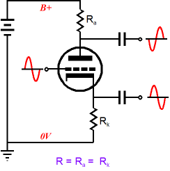
Hybrid Split-Load Phase Splitter One of my favorite split-load variations is the circuit I came up with for blog 135. It is based on thirds and quarters—in other words, mathematical slight of hand that just tickles me greatly.
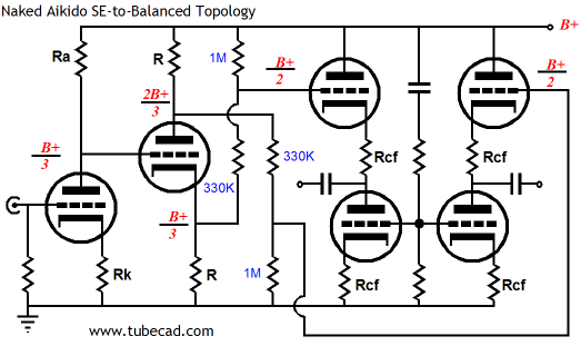
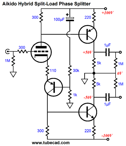
This circuit receives an unbalanced input signal and turns it into balanced output signal. At the same time, it strips away the power supply noise. Yet, this complex circuit only holds two coupling capacitor—it does sport a balanced output after all. A line stage amplifier, however, seldom needs big voltage swings at its output, so the split-load phase splitter is not a liability. A power amplifier, on the other hand, does require huge input voltage swings, which the split-load phase splitter finds hard to produce. (This is one of the reasons that I have long argued that the split-load phase splitter should be the input stage or at least come early in the push-pull power amplifier.) The following hybrid split-load phase splitter circuits allow huge voltage swings to be created, as the solid-state devices do not suffer from the big voltage drops that that triodes incur. The first circuit is quite simple, appearances to the contrary. The triode's current conduction is varied by the input signal at its grid. This current variation is then relayed to the PNP and NPN output transistors. Both transistors amplify in current phase. In other words, both transistors increase and decrease in current conduction in unison. So how is phase splitting possible? The PNP transistor will pull up ground and the bottom transistor will pull down from ground when they increase in conduction, thereby creating two anti-phase output signals. With the +/-100Vdc rails, the following circuit should be able to swing +/-45Vpk output swings from each phase, which could easily drive an EL34 or KT88/6550 pair of output tubes to full power.
One problem with the above circuit is that its PSRR is only so-so. The Aikido workaround is to inject some of the positive power supply rail noise into the PNP transistor's base, which will undo the current variations in the triode due to power-supply ripple. The resistor ratio is the same as the amplification factor of the triode used.
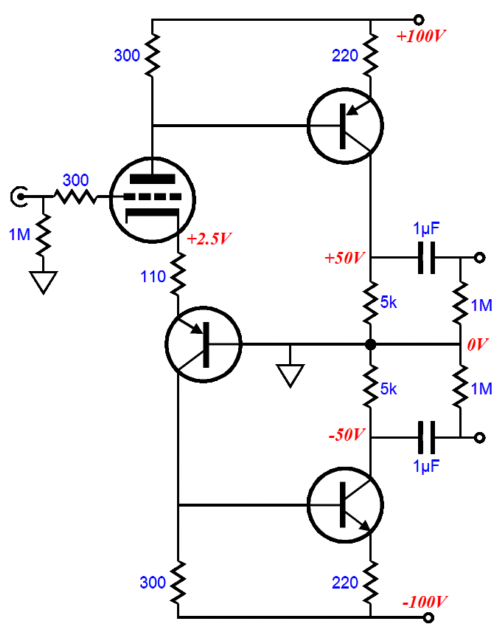
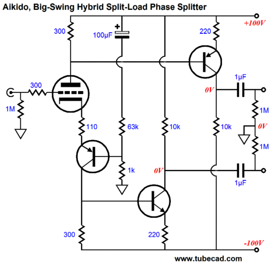
If even greater voltage swings are needed, the the following circuit will work well. This variation terminates the collector resistors to the opposing power supply rail, rather than ground. With the +/-100Vdc rails, the following circuit should be able to swing +/-95Vpk output swings from each phase, which could easily drive a 300B or 211 triode.
Note how the resistor ratio in the two-resistor voltage divider changed. This time, the ratio is closer to 2mu. Of course, higher rail voltages could be used and the transistors could be replaced by high-voltage MOSFETs.
//JRB |
|
I know that some readers wish to avoid Patreon, so here is a PayPal button instead. Thanks.
John Broskie
E-mail from GlassWare customers:
And
High-quality, double-sided, extra thick, 2-oz traces, plated-through holes, dual sets of resistor pads and pads for two coupling capacitors. Stereo and mono, octal and 9-pin printed circuit boards available.  Aikido PCBs for as little as $20.40 http://glass-ware.stores.yahoo.net/ Only $12.95 TCJ My-Stock DB
Version 2 Improvements *User definable Download or CD ROM www.glass-ware.com |
||


| www.tubecad.com Copyright © 1999-2011 GlassWare All Rights Reserved |