| John Broskie's Guide to Tube Circuit Analysis & Design |
21 April 2010
PS-3: High-Voltage Power Supply & Heater Regulator Although I do love my old, tube-based, Hewlett Packard, adjustable, high-voltage regulator because it is so robust, it is not very DC-voltage-stable nor ripple-free. My workaround has been to build up three chassis, each holding a high-voltage and low-voltage power supply and nothing else. These test-bed boxes allow me to house and power a tube circuit prototype in less than five minutes. Each chassis holds a different B+ voltage: unregulated 170Vdc, regulated 240Vdc, and regulated 300Vdc; and all hold a 12Vdc regulated heater power supply. My adjustable high-voltage regulator and three test boxes have furthered my tube audio experimentation greatly. But when I want to build a finished standalone tube-audio project, say a tube-based crossover or buffer, I am stuck in the same predicament that most readers are in: how do I include an effective and painless power supply? Many times the project does not warrant a PS-1 or Janus regulator's low noise, or it might demand greater current flow than these regulators can provide.
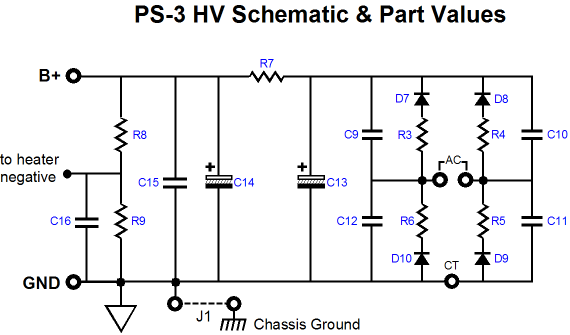
Like the tube-rectified PS-4 power supply, the new PS-3 power supply bestows an easy out. The PS-3's PCB is only 4" by 4" and, like all my PCBs, is extra thick (0.094 in), US-made, with heavy 2 oz-copper. The PCB holds both a simple RC pi-filtered high-voltage power supply and a low-voltage power supply and low-voltage regulator. The low-voltage regulator is meant to power the tube heaters; the high-voltage power supply, the rest of the tube circuit.
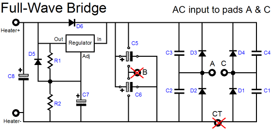
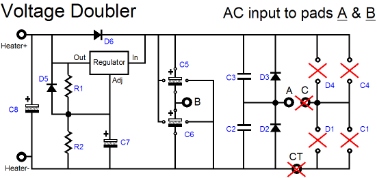
The high-voltage portion of the PS-3 power supply uses four solid-state ultra-fast-recovery rectifiers, a simple RC pi-filter to achieve a fairly quiet B+ voltage, which can span from 100V to 350V. The 5W series resistor (300, 1k, 1.5k, 10k supplied) can be replaced by an external choke. And just like the PS-4, the PS-3 can DC reference the heater regulator to ground or 1/4 of the B+ voltage or left floating, with only a shunting capacitor to ground. The PS-3 power supply PCB is equal to raw DC power supply portion of the PS-1 PCB and an H-PS-1 PCB welded together. It's B+ output voltage is not regulated, but then it is neither as expensive nor complex nor fragile nor as current-limited as the typical high-voltage regulator. The low-voltage regulator’s power supply is flexible enough to allow either a conventional full-wave-bridge and full-wave center-tapped rectifier arrangement or a two-rectifier voltage-doubler configuration, allowing for more latitude in power transformer selection; this regulator can be set to either 6.3V or 12V or 12.6V.
Most power transformers intended for tube use hold 6.3Vac heater windings, not 12.6Vac. When applying AC to the heater elements, the lower voltage works well. But when delivering regulated DC voltage to the heaters, a 12.6Vac winding is preferred, as the regulator requires voltage headroom and the rectifiers will entail their own voltage loses. Fortunately, the PS-3 heater power supply can be configured as a voltage doubler setup, which will effectively double a 6.3Vac winding's voltage, but at the cost of half the potential current delivery (there are no free lunches).
From my e-mails, I know that many solder slingers are buying the following Hammond power transformer:
This transformer will work beautifully with the PS-3 power supply PCB; the raw B+ voltage developed is about 350Vdc (no center-tap connection), which after flowing through a 1k series resistor at 50mA, leaves the power supply at 300Vdc. Voltage doubling the 6.3Vac heater winding yield more current than you might conclude from the 2A rating. How's this free lunch possible? Nothing free here; since the high voltage primary, once rectified, could deliver about 85mA and since we are only drawing 50mA, the transformer's core is unburdened enough to delivers more current into the heater winding. I know this from actual experience, as I bought one of these transformers and gave it a test run, which it passed easily, never getting hot or buzzing, even with a heater load of 1.2A.
My friend Glenn needed an external high-voltage power supply for a tube-based project he put together. The PS-3 power supply fits in the small 5in-wide power supply chassis and works perfectly. The power supply puts out 220Vdc and 12Vdc and runs cool. The complete PS-3 kit is only $39 USD and is available at the GlassWare-Yahoo store. For more information, click on the PS-3 user guide image at the top right of this page.
Tringlotron Once Again
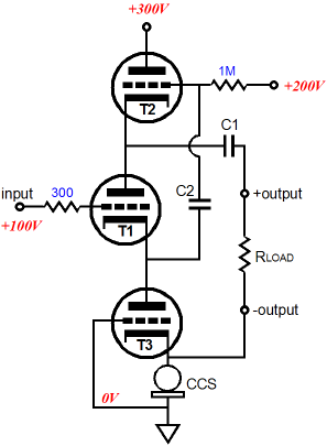
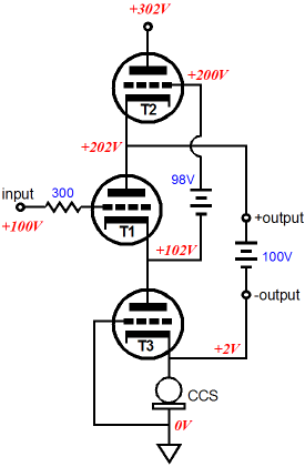
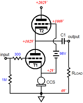
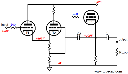
Tringlotron Deconstructed Why do I feel the need to dismantle, break into sub-sections the Tringlotron topology? As I wrote my explanation of the Tringlotron in my last blog entry, I knew that it would provoke much head scratching. Where to start? One of my favorite conceptual tools is thinking in extremes. For example, alternating infinity and zero as the load impedance. With the Tringlotron topology, zero load impedance is a good starting point in understanding how the circuit works. In the schematic below, we see capacitors C1 & C2 replaced with batteries, batteries that offer zero impedance.
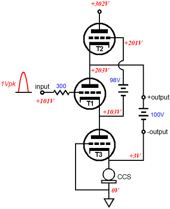
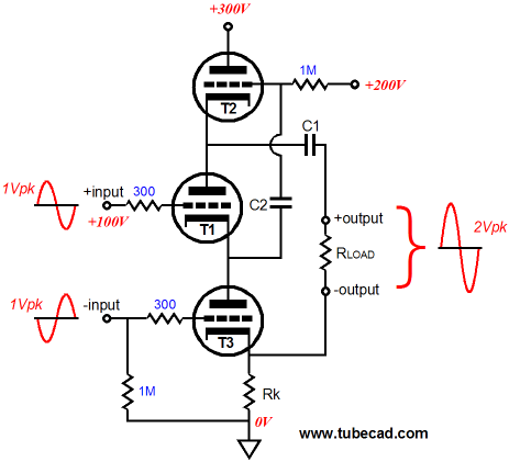
The batteries establish the correct DC voltage relations, while relaying 100% of the AC signals. (Of course, huge capacitors would offer near zero impedances at audio frequencies, but 100-farad capacitors are so rare that few could imagine their existence.) Now imagine a 1Vpk positive-going pulse applied to the Tringlotron's input.
The grid sees the increased grid voltage and responds by its cathode climbing by 1V, which in turn is relayed to the triode T2's grid, which provokes its cathode to rise by 1V, which then causes triode T3's cathode voltage to increase by 1V. Indirect , very indirect. The constant-current source continues conducting its fixed current, but the bottommost triode has seen its grid-to-cathode voltage decrease by 1V (its cathode-to-plate voltage remains constant), thus its current conduction must drop by 1V against the triode's transconductance. For example, if the triode presents a gm of 5mA/V, then triode T3's current draw must fall by 5mA. Since Triode T1 is in series with T3, its current must fall off by 5mA as well. And since the constant-current source and triode T2 provide the only current paths from ground to the B+ connection, triode T2 must see a constant-current conduction equal to that allocated by the constant-current source. But if triodes T1 & T3 see their current conduction fall by 5mA and the constant-current source and triode T2 experience a constant current conduction, say 10mA, where dose the extra 5mA of current flow come from? The answer is the load, which in this case is the zero-impedance battery, which must undergo a 5mA current flow through its cells.
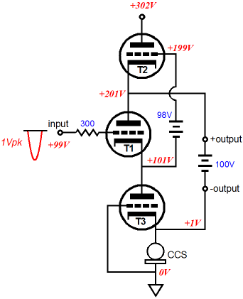
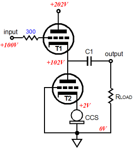
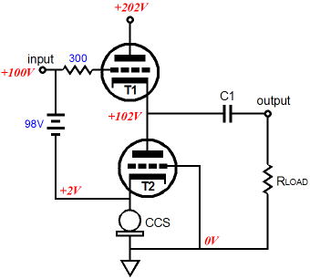
Conversely, if the Tringlotron's input sees a negative-going 1Vpk pulse instead, then T1's cathode must fall by 1V, which will force triode T2's grid down by 1V, which will cause its cathode to fall by 1V, which then is relayed to triode T3's cathode, whose voltage drops by 1V, thereby provoking its current conduction to grow by + 1V against the triode's transconductance. In this example, by 5mA. And once again, as triode T1 is in series with T3, its current conduction must grow by 5mA as well. This time we have triodes T1 & T3 conducting 15mA, but the constant-current source and triode T2 limit the current flow from ground to B+ to 10mA. Where does the extra 5mA of current go? Once again, the answer is the battery; this time the load battery must summon the extra 5mA, whereas it had to absorb missing 5mA in the previous example. Had the load been omitted—infinite load resistance, in other words—the current conduction would remain constant throughout the entire circuit and the output would almost exactly mirror the input signal. Okay, my guess is that 50% of those who hadn't got it before now get it. For the remaining 50%, let's take apart the Tringlotron even further. In the schematic below, we see a simple cathode follower with the slight modification of replacing the cathode resistor with a triode and a constant-current source. Such a design might appear extravagant, but not overly complex, as active cathode load only approximates a very large resistance. Because the bottom triode is directly in series with the constant-current source, it must always conduct the same amount of current as the constant-current source. Triode T1, on the other hand, is free to increase or decrease its conduction, as the external load will absorb the difference. The following circuit is functionally the same as the previous one, in that triode T1's conductions is fixed by the constant-current source and T2's varies with the input signal. The only real difference is that whatever distortion the bottom triode imparts at its cathode is now superimposed on the input signal before it is relayed to the T2's grid.
In this last deconstruction, we see a push-pull output stage (all the previous example were pure single-ended efforts). I show this circuit only to illustrate how a triode can receive its input signal from its cathode, not just its grid. As the input signal swing positively, the top triode conducts more; the bottom, less. As the signal swing negatively, the top decreases in conduction, while the bottom increases. The external load receives the delta, the difference between top and bottom triode current conduction. (The balance is very poor for high-impedance loads and quite good with super–low impedance loads with this output stage, as no provision is made for the top triode's cathode moving with the input signal. Moreover, the following circuit presents a low input impedance, not the usual cathode follower's ultra-high impedance.)
Rk-Based Tringlotron
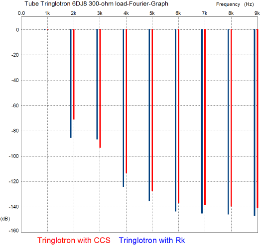
How did it work out? Not bad, not bad at all. The gain falls to 0.83 with a 6DJ8/6922 and a 300-ohm load and 1Vpk input signal and a cathode resistor of 182 ohms. More importantly, the distortion did not skyrocket; in fact, the total harmonic distortion goes down.
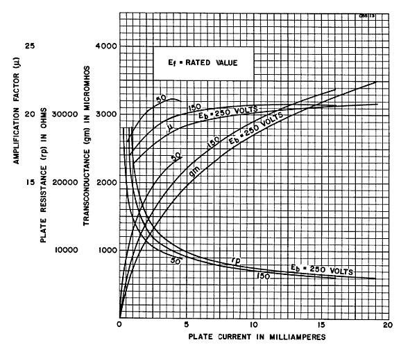
Other than the 3rd harmonic, the Tringlotron with the cathode resistor beats the constant-current-source version. How is this possible? Don't constant-current sources always yield the lowest distortion? First, we should never forget that SPICE simulations are not reality. The tube models most commonly used in SPICE assume the triodes exhibit a perfectly constant amplification factor (mu or µ); they don't in reality. Below is from a 6SN7data sheet and it plots the 6SN7's mu over cathode current at three plate voltages. By the way, the 6SN7 is a amazingly linear device and other triodes are not nearly as linear.
In SPICE, the 6SN7 model's mu plot line will draw a flat line at a mu of 20, from 0mA to 20mA at all plate voltages. Paradoxically, this SPICE-world of constant mu will favor the tube SPICE models and CCS, when the triode is used in a grounded-cathode amplifier with a CCS as the plate load. But the Tringlotron is not a simple grounded-cathode amplifier and its constant-current source is located at the cathode, not the plate. In the real world, constant-current sources will maximize the gain realized, thereby increasing the feedback ratio, which in turn will further reduce the distortion from an amplifier. The appearance of a free lunch disappears once you factor in the increased input signal needed to drive the cathode-resistor-based Tringlotron to the same output voltage swing. In conclusion, try the resistor version before trying the constant-current source one.
Variations on the Tringlotron
Remember that the topmost active device sees a constant current flow and that its cathode, emitter, or source must be able to swing as wide as the input signal that the Tringlotron is presented. The next variation creates an unbalanced-to balanced converter. A balanced-input Tringlotron that sums the differential signal is truly interesting and it might find a happy application as the unbalanced-to balanced converter following a DAC with differential outputs.
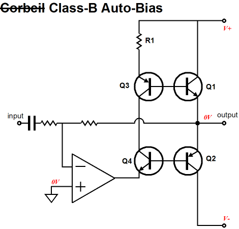
Before anyone get all wobbly at the knees at the prospect of having to listen to a push-pull buffer, I must point out that the Tringlotron's functioning remains strictly single-ended in nature, in spite of the the balanced inputs. In fact, this circuit's intrinsic single-ended functioning is revealed by the current swings that remain confined to the limit set by the idle current. In contrast, a true push-pull buffer could break free of the idle current limit by moving out of class-A into class-B operation, wherein one device shuts off and the other conducts wildly.
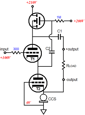
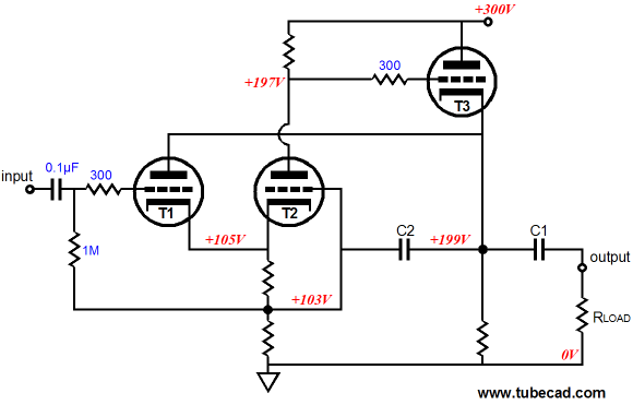
One disadvantage to the Broskie Buffer circuit that I mentioned was the relatively low input impedance (10k with a 6DJ8). The easy workaround is to drive the buffer's input with a cathode follower.
Triode T1 drives triode t2's cathode directly; at the same time, capacitor C2 drives T2's grid. The result is that T1's cathode is effectively attached to a 10k load, which greatly lowers its distortion contribution. One problem is that triodes T1 & T2 see vastly different cathode-to-plate voltages, which might exceed T1's cathode-to-plate voltage limit and will certainly double its dissipation compared to T2, assuming equal idle currents.
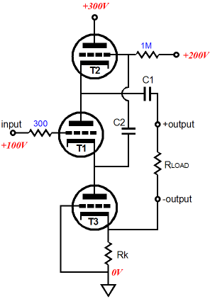
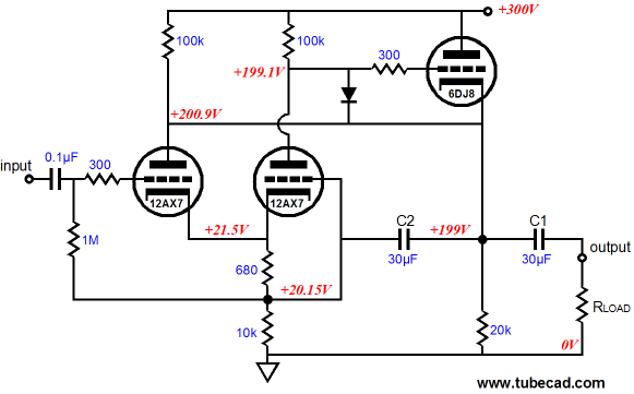
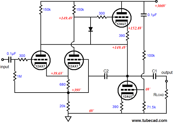
The workaround is to attach T1's plate to T3's cathode. Now both T1 & T2 see roughly the same cathode-to-plate voltages and T1 is nested in a unity-gain bubble of sorts. For example, if T1's grid sees a 1Vpk positive swing, so will its cathode and plate. The new problem created by this reconfiguration is that triode T3 now must absorb T1's current flow, which must further increase its dissipation. The workaround applied to the workaround is to give T1 its own current path to B+ via a plate resistor, while still retaining the connection t the output tube's cathode. Let's put all this together and add the missing part values and voltages.
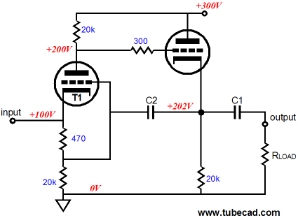
Crazy looking, I agree. The 12AX7 needs plate voltage if it is going to produce little distortion, so the 300V was not sliced up into three 100V segments; instead, the 12AX7 gets almost 180V to play with while the output tube, the 6DJ8/6922, gets 100V and its cathode must drive its 20k cathode resistor in parallel with the load resistance and the 12AX7 pair's common 10k cathode resistor. The mystery diode protects the output tube at startup, when its cathode is cold and not conducting but the B+ voltage is present. Once the tubes heat up, the output tube's cathode will climb to a positive voltage than its grid, so the diode will no longer be forward biased and it will turn off. The 0.1µF input coupling capacitor allows us to hook up this unity-gain buffer to the signal device we wish, without having to worry about DC voltage relationships. Because of capacitor C2 bootstrapping the other end of this coupling capacitor's 1M bias resistor, the 1M resistance gets amplified a great deal, so a much smaller valued capacitor can be used. Okay, have we arrived? Is this audio perfection? I know that 99% of audiophiles only want stuff and are completely indifferent to how the stuff works, but such questions always irk me. The one universal principle of analog electronics is that we never arrive; we can always go further. We only arrive at the end of our patience or persistence or imagination or cleverness or our wallet's endurance, never at the absolute electron flow. Having said that, I can think of one easy improvement: adding an Aikido cathode follower.
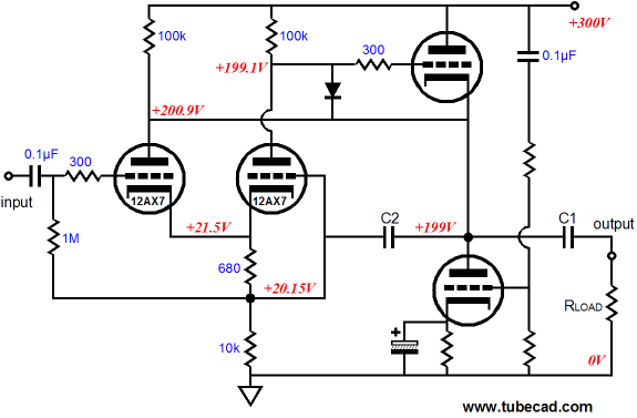
In the schematic above, we see the output tube's cathode resistor replaced by an active load, a load that actively nulls the power-supply noise at the output. With some tweaking, it is possible to get insanely good PSRR figures, say -60dB. If the lowest possible Zo is not the goal, then the following variation is prefrred.
(Of course, different tubes could be used. Remember different tube types do not make a different topology; no more than a red Honda Fit is a different model from a blue Honda Fit.)
Letters to the Editor
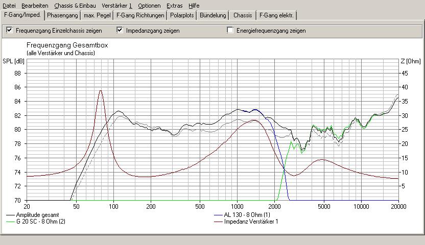
Thanks Christian. Yes, the added resistance can throw a speaker's Qts off, as
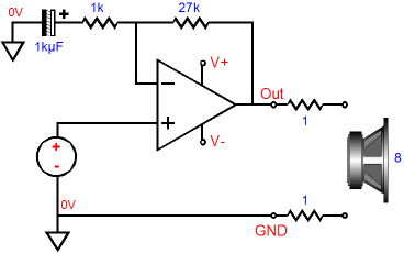
In the past, I have used large-valued series resistors to greatly increase a loudspeaker's Qes so that an otherwise over-damped woofer could be used in a dipole. For example, placing an 8-ohm resistor series with an 8-ohm woofer can bring a Qts of 0.29 up to something like 0.8, which will greatly improve the low end output, but at the expense of a -6dB reduction of SPL in the midband. The workaround I used was to place two such woofer-resistor combinations in parallel, which brought the parallel load impedance back down to 8 ohms and restored the SPL. I have been meaning to post the following e-mail for a long time now.
Thanks Louis. I am sure that you are right and I wish I could better read French, as there is a lot of interesting developments going on in audio in France today.
Next Time
//JRB |
E-mail from GlassWare Customers
High-quality, double-sided, extra thick, 2-oz traces, plated-through holes, dual sets of resistor pads and pads for two coupling capacitors. Stereo and mono, octal and 9-pin printed circuit boards available.  Aikido PCBs for as little as $24 http://glass-ware.stores.yahoo.net/
|
|||


| www.tubecad.com Copyright © 1999-2010 GlassWare All Rights Reserved |