| John Broskie's Guide to Tube Circuit Analysis & Design |
29 Oct 2007
The Other John Broskie
If you like this photo as it's reproduced above, you should see it full-size, printed on texured paper and in its frame. Magnificent. Please do click on the buttons below and visit his online photo galleries; I am sure you will be as impressed as I am by his talent. Now, if only I could get him to take pictures of old tube gear for a calendar…
Nelson Pass's Zen Meets John Broskie's Aikido
(See the tiny Aikido PCB floating above the red amplifier.) Intriguingly enough, at the audioXpress website you can download the entire article for free: this issue's second part, and last issue's first part. And please do download both parts of his article (and pick up the current issue of audioXpress, if you don't subscribe), as both parts are quite interesting, for the ZenKido sidesteps the usual DGNNAHA (Dear God No, Not Another Hybrid Amplifier) response, as Mr. Moore has many tricks up his sleeve. For example, while he is using a Pass-inspired constant-current source (a constant-current source that is more active than you might imagine at first), he uses it as a load for the output MOSFET's source—the MOSFET operates in a source-follower configuration—but the constant-current source does not directly attach to the MOSFET's source, but is found riding high above it, coupling only through the power supply. Furthermore, he has shifted the ground reference, with an almost Broskie-like disregard for cast-in-concrete tradition and stolid thinking. I will not draw out the schematic, as figure 6 in part one of his article nicely makes the point.
Aikido Long-Tail Phase Splitters
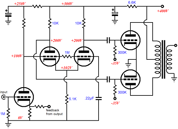
The long-tail phase splitter input grid is directly coupled to the input stage and the 0.22µF decoupling capacitor grounds the phase splitter’s second grid, with the 1M resistor setting the DC bias voltage for the second grid. Now, if we assume a perfect power supply, completely free of hum and signal-induced noise, then everything will work well. On the other hand, if accept the reality that the power supply will not reject all the rectifier ripple and that it will not offer a zero impedance to the signal currents flowing into it, then things will get messy. For example, the long-tail phase splitter offers a negligible PSRR, so whatever power supply noise rides on the +300V connection will also ride on the phase splitter’s output signals. In addition, whatever power supply noise rides on the input stage’s +250V connection will be amplified at the phase splitter’s outputs, as it will be indistinguishable from the desired input signal. In theory, the noise from the +300V connection is the more benign, as it is a common-mode signal that will cancel in the output stage. And it will, up to a point -- and that point is where one tube stops conducting, while the other conducts heavily. If one output tube is no longer conducting, it is effectively out of the circuit and no long can provide the countervailing noise current to cancel the other tube’s noise contribution. This, I believe, explains why so many power amplifiers that seem quiet at idle can sound garbled and coarse when playing music. (A real class-A, push-pull power amplifier is immune from this sudden-onset-of-congestion distortion.)
The above schematic shows a simple Aikido transformation. Here both the input stage and the phase splitter share the same B+ connection, so whatever voltage perturbation rides on the 300V rail will be divided by three at the input tube’s plate and at the two-capacitor voltage divider’s nexus. Thus, the long-tail phase splitter will see the same noise signal in phase at both its grids, which means that the noise will be equally amplified by the following formula: Gain = muRa/(rp + Ra + 2[mu +1]Rk) A quick inspection establishes that the higher the mu, the closer to unity gain the phase splitter attains. If it did achieve unity gain, the power supply noise would altogether drop out of the phase splitter’s outputs, as Noise – Noise = 0 (the amplified noise is phase inverted at the plates). For example, if a 6SN7/6CG7 is used in the long-tail phase splitter, the final PSRR will come in at about -20dB, which is much better than the -0.4dB that would otherwise obtain. If the resistor values are tweaked, an even greater PSRR figure is possible.
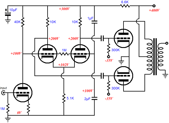
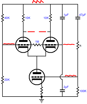
On the other hand, if you do not want to think that hard or you do not want to rewire anymore of an existing amplifier than you absolutely must, the super simple Aikido trick is just to add the second decupling capacitor from the phase splitter’s second grid to the input stage’s B+ connection, as shown above. This technique will prevent the input stage’s output noise from being differentially amplified by the phase splitter, but it will not eliminate the common-mode power supply noise at the phase splitter’s B+ connection from leaking into the phase splitter’s two outputs. So, in terms of low-noise, the first Aikido transformation is a better way to go. The problem with the first technique is that the math works against you in terms of potential voltage swing, as ideally the common-cathode resistor should see a larger voltage drop than the phase splitter’s plate resistors do, which would limit the possible voltage swing at the plates. One way out of this corner is to go back to using an active load in place of the common-cathode resistor. In the schematic below, the leftmost resistors (40k and 20k) represent the input stage, in both AC and DC terms. These resistors stand in a 2:1 relation, as do the 1µF and 2µF decoupling capacitors. By matching these two voltage dividers, we ensure that the long-tail phase splitter sees the same signal at both of its inputs, which can then be largely ignored because of the phase splitter’s high CMRR. Note, however, how the larger resistor sits atop the smaller, whereas the larger capacitor sits below the smaller capacitor. (Capacitor-based voltage dividers are an inversion of resistor voltage divider in term of capacitance value, but not in terms of impedance. The problem lies with describing a fundamentally negative thing, resistance, in a positive fashion; ideally, we could have used a resistor’s conductance value for its label, rather than the inversion of its conductance.)
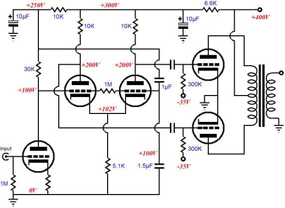
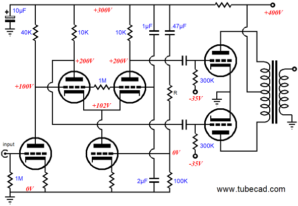
The value of resistor R depends on the triodes used. The signal that appears at the bottommost triode’s grid will be amplifier- and phase-inverted at the phase splitter’s outputs, which allows us to cancel the power supply noise at the outputs. In the schematic below, we see the entire power amplifier. (The grid-stopper resistors were omitted to increase clarity of topology; they are needed in a real amplifier.)
Next Time
//JRB
*My uncle, John Broski's father, apparently didn't like having a long Polish last name, so he shortened it by one letter ;)
|
Now accepting
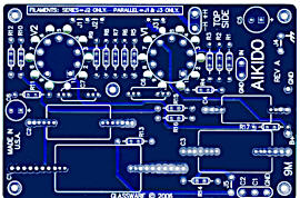
High-quality, double-sided, extra thick, 2-oz traces, plated-through holes, dual sets of resistor pads and pads for two coupling capacitors. Stereo and mono, octal and 9-pin printed circuit boards available.  Aikido PCBs for as little as $24 http://glass-ware.stores.yahoo.net/
Now accepting Support the Tube CAD Journal & get an extremely powerful push-pull tube-amplifier simulator for TCJ Push-Pull Calculator
TCJ PPC Version 2 Improvements Rebuilt simulation engine *User definable
Download or CD ROM For more information, please visit our Web site : To purchase, please visit our Yahoo Store:
|
|||


| www.tubecad.com Copyright © 1999-2007 GlassWare All Rights Reserved |