| John Broskie's Guide to Tube Circuit Analysis & Design |
|
18 October 2007
Yes, I know that I should be covering how to apply Aikido-audio techniques to the long-tail phase splitter. I did not expect that I could post until after the Nor-CAl-DIY meeting, so I will cover How to Design an SE Power Amplifier instead. I get many e-mails that ask "How do I design an SE amplifier for a...?" The tube is usually some rare item that the correspondent was lucky enough to find at a garage sale or inherit, but which has never been used in a power amplifier. First of all, I must say that asking for a design procedure is in itself something of an accomplishment, as most solder slingers go about in a strikingly different way. They bypass all the boring math stuff and race towards the prize. Their first step is to ask their friends or look on the 'Net for the best tube to use and, for example, decide on a 211. The next step is to search for the best output transformer, say a Bartolucci 23, whose 26W output limit seems perfect for the 211. The next search is for the best power supply and, for example, an Ultra-Mega VoltMaster 240V power supply is chosen, as it seems to be getting the best reviews at DIY sites. The last step is to find the best frontend to the drive the output tube; thus, I will get an e-mail asking if a 6SN7-based Aikido line stage amplifier will drive the 211 to full power. I then reply that it cannot, but it is used nonetheless. Can you imagine just how great this amplifier will sound? I cannot. In fact, I cannot imagine it making much sound at all. Only a government-appointed committee could design a worse single-ended power amplifier. What’s wrong with it? A shorter list would result from asking instead, What’s right about it? The answer is that it looks cool, 211s always look impressive. Now for the longer list, the output tube and output transformer do not mate well, as the Bartolucci 23, which just might be a great output transformer, presents a primary impedance of only 500-ohms, which is far too low for a relatively high-rp triode like the 211. Second, the power supply is ridiculously low for a relatively high-mu triode like the 211. Third, the 6SN7-based Aikido amplifier develops a gain of only 10 (+20dB) and the 211 will need to see big +/-50V swings to get it to move. Finally, the biggest mistake was to substitute fashion and gossip for a design procedure and a hand calculator. Ouch! Okay, so what is the correct design procedure?
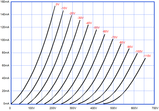
The first step is to get hold of the tube's data sheet. (Try Frank Philipse's website, www.tubedata.org from the Netherlands.) Why? We need to know a few critical pieces of tube data, such as the maximum steady cathode-to-plate voltage, the maximum steady cathode current, and the plate dissipation. To this list, we can add, the minimum cathode current, which we will not find in any data sheet, but which we can glean from inspecting the plate curves. (The triode plate curves shown here belong to no tube, as I made them up for demonstration purposes. Nonetheless, the same procedure applies to all tubes, even make-believe triodes. )
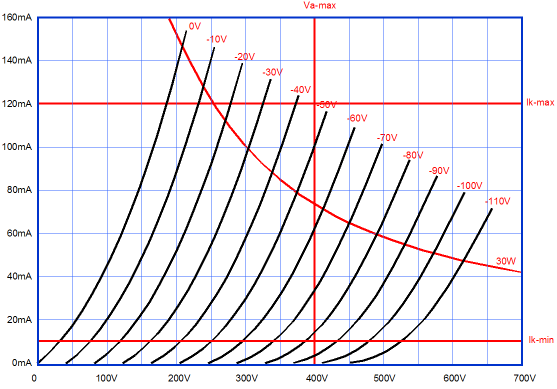
From inspecting the curve, we can set the lower limit to cathode current conduction to 10mA, as above this current draw, the triode is fairly linear (far too much so, in fact; I should have built in more low-current slop). While we must observe these maximum limits, understand that the maximum voltage, current, and power limits hold for idle conditions and that we are allowed to briefly exceed them while playing music (unless, you play at ear-bleedingly-loud levels and your musical tastes run towards organ and synthesizer music). For example, a tube with a 400V plate-voltage limit, can comfortably sit at 350V at idle and then, without damage, at full output, swing up to 700V. The second step is to decide how hard to run the tube. Since all single ended amplifiers run in strict class-A, heat is to be expected. By looking in tube data sheets or by inspecting the above graph, we discover that the maximum plate dissipation is 30W. My own self-imposed limit is 75% of the power dissipation limit at idle, which in this example equals 22.5W. Applying that 75% percentage to the to the tube requires knowing what either the B+ voltage or the idle current will be. I always set the B+ first and at something between 80-90% of the maximum plate voltage (400V for this tube).
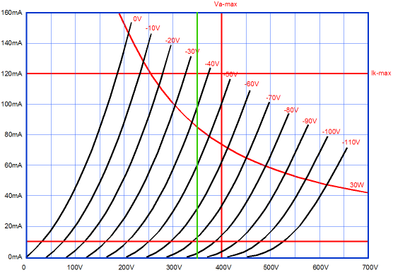
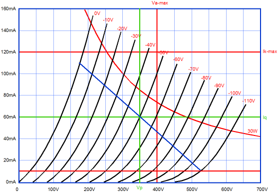
In this design example, let’s use 350V for the plate voltage. (The actual B+ voltage will have to include the voltage drop across the output transformer’s primary and cathode resistor, if the output stage is self-biased.) Now we are set to fly through the rest of the calculations. Starting with the idle current, 22.5W divided by 350V equals 64mA, which we will adjust down to 60mA. Next, since we set 10mA as the lower limit of current conduction, we can figure out the maximum current draw by subtracting the lower limit from the idle current (Iq), which equals 50mA, and which added to the idle current equals 110mA. Now we draw a loadline starting from the intersection on the 0-volt grid-line and 110mA and passing through the 350V and 60mA intersection and ending at the 10mA and 525V intersection. Finding the loadline’s impedance is easy enough, as we need only divide the voltage spanned by the current climb; in this example, (525V – 175V) / (0.11A – 0.01A) = 350V / 0.1A = 3500 ohms.
Assuming fixed bias, the negative bias voltage is -50V; assuming self bias, the cathode resistor is equal to 50V / 0.06A, or 833 ohms (the B+ will have to be raised by the 50V lost across the cathode resistor, so 400V would be the new B+ voltage). From inspecting the graph, we see that the grid must see a positive voltage swing of +50V and a negative swing of -60V. Why the discrepancy? Tubes are not perfectly linear, as they are much easier to turn on than to turn off. (When designing the driver-stage, I would strive to ensure a larger negative swing than a positive swing. Ideally, we would like to find a driver tube that inversely matched the output tube, swinging down more aggressively than up by the same ratio. Yet, the Aikido frontend has beat all my previous attempts. Strange. My guess is that lowering 2nd hamonics at the cost of more 3rd harmonics is a bad deal.) From inspecting the graph, we can also determine the maximum output power. The 175V peak voltage swing and the 0.05A current peak current swing multiplied against each other yields a peak instantaneous power of 8.75W, which means that the actual RMS-derived power for sine waves is half that amount, or 4.375W. Wait a minute; I read that many are getting 25W out of single 2A3s, so why would a power tube with twice the dissipation only yield a miserly 4.375W? Well, the easy answer is that no one is getting 25W from a single 2A3, that the power measuring technique method used by many is to gauge the heft of the output transformer and guess accordingly, as no sound electrical engineering explanation can be offered for such an exaggeration…. (Maybe they were giving their 2A3s that new all-natural supplement that I read about in my spam e-mail everyday, Megatube…. Guaranteed to increase wattage by 10 to 30 watts.... Imagine the smile on your girlfriend's face as she listens to your new 80 watter....) Of course, if this is just too much hard work, you can always go back to the gossip-design approach; as German researchers have shown, and which I have always suspected, Gossip is more powerful than truth.
//JRB
|
Now accepting
High-quality, double-sided, extra thick, 2-oz traces, plated-through holes, dual sets of resistor pads and pads for two coupling capacitors. Stereo and mono, octal and 9-pin printed circuit boards available.  Aikido PCBs for as little as $24 http://glass-ware.stores.yahoo.net/
Only $19.95
Download or CD ROM www.glass-ware.com Goldpoint™
For over a decade, Goldpoint™ has provided equipment designers and audio enthusiasts the best 24-position level controls made. We offer completely assembled and "blank" stepped attenuators.
|
|||


| www.tubecad.com Copyright © 1999-2007 GlassWare All Rights Reserved |