| John Broskie's Guide to Tube Circuit Analysis & Design |
15 July 2007
If you don't make mistakes, you're not working on hard enough problems. And that's a big mistake.
Frank Wilczek (American physicist and Nobel Prize winner 2004) Wrong Turn
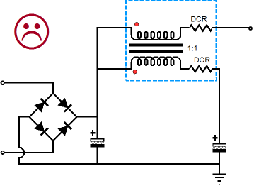
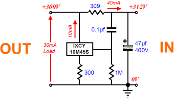
What's wrong with it? First, it requires an air-gapped transformer, as the top winding see a sustained DC current, which means that the core must magnetize because of the steady current flow. Second, in this configuration, the transformer functions like a choke, not a transformer, as only the series inductance fights the power supply noise. In other words, no feedforward shunting, no complete noise nulling, no getting away with cheap and readily available isolation transformers. The big problem is that low frequencies and passive filters do not go together, except when the inductors and capacitors are huge. Then when we add to the this predicament the fact that high-voltage and large-valued capacitors only go together at great expense, the problems with passive solutions become even worse. Thus, it made perfect sense for old tube gear to sport ridiculously low idle current through all its stages, as the trivial current draw allowed the use of small-valued power-supply capacitors and small inductors. Today, this solution will not do, as line stage amplifiers are expected to drive loads tens times lower in impedance than in the past, as many solid-state amplifier present an input impedance of only 20k or even just 10k; and 0.7mA of idle current through the output tube will not cut it. Besides, modern fancy interconnect often holds a much higher capacitance than old cables; and this capacitance must be charged and discharged with high current. Active power supply filtering, on the other hand, can be small, cheap, and more effective at low frequencies, which 50Hz and 60Hz certainly are. The following circuit is a simple feedforward shunt regulator that uses an IXCY 10M45S high-voltage, constant-current source.
Whatever power supply noise that exists on the right of the circuit is relayed to the IXCY 10M45S’s gate, which then induces an equivalent noise signal to appear across the 300-ohm cathode resistor (yes, cathode resistor), which then creates an anti-phase noise current that flows through the 309-ohm series resistor, thereby canceling the power supply noise at the circuit’s left. (The reasoning behind using mismatched resistors, 300 ohm and 309 ohms, is that the IXCY 10M45S is not likely to achieve 100% unity-gain at its cathode.)
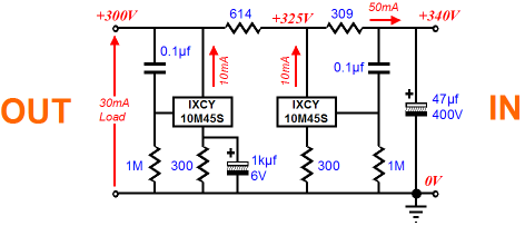
Once again, the problem with the feedforward shunt regulator is that, although it does an exemplary job of stripping away the raw power supply noise, it does little to eliminate the signal-induced noise from the tube circuit being supplied. So, here is where we look both ways by adding a conventional feedback-based shunt regulator after the feedforward shunt regulator.
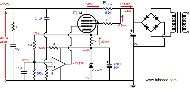
Once again, you are invited to a wedding between two dissimilar technologies (solid-state and vacuum-state) and two different shunt techniques (feedback and feedforward) into one high-voltage regulator. But first, we need to look at a circuit from the last blog.
What’s wrong with it? Nothing other than it is missing some supporting safety parts, which are shown below.
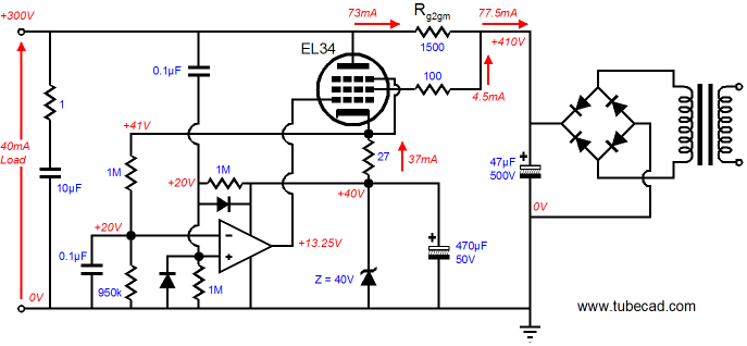
The added diodes protect the OpAmp from high-voltage spikes at startup and when the output is shorted to ground. Speaking of the last blog, TCJer, Rene', has come up with a cool name for the following type of circuits, wherein, a P-version of some solid-state device has its source or emitter attached to a tube’s cathode, a “Bastode Circuit.” I like it a great deal. Note that these circuits are not cascodes, being closer to cathode-coupled amplifiers.
By the way, here is what the circuit looks like with added safety diodes.
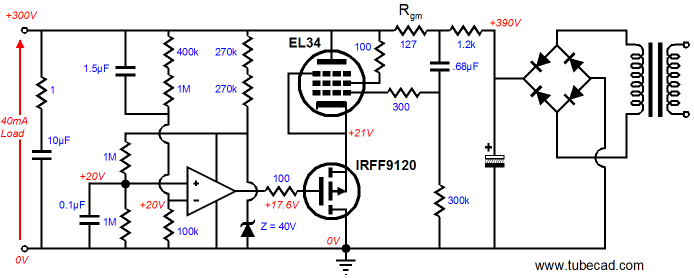
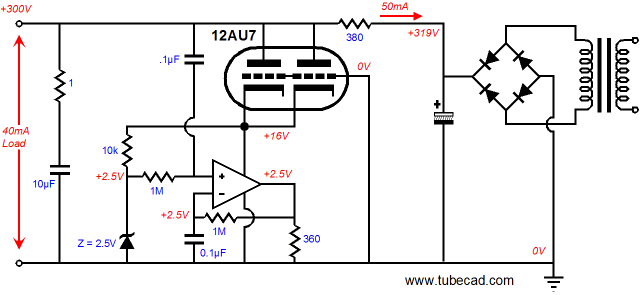
Now for some new hybrid circuits. In the following schematic, we see a shunt regulator that uses the 12AU7 to cascode the OpAmp, which does all the B+ clean work.
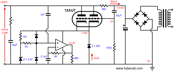
The OpAmp also establishes a fixed idle current through the 12AU7, as a DC feedback extends from the OpAmp’s output to its negative input. Now let’s modify the circuit, making it safer and more effective.
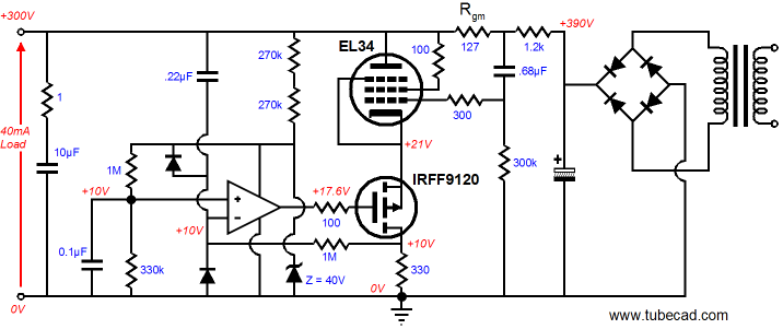
The zener only conducts when something has gone wrong. The 12AU7's triodes now share in the work of cleaning up the output voltage, as it now constitutes a feedforward shunt regulator. Of course, a different tube could be used, such as a 5687 or 6H30 or 12B4 or any of several dozen high-voltage, high-current triodes. //JRB
Mésalliance (mā-zăl'ē-əns, mā,ză-lyäns') noun. A marriage with a person of inferior social position.[French : més-, bad (from Old French mes-) + alliance, alliance, from Old French aliance.] From the American Heritage Dictionary.
|
|


| www.tubecad.com Copyright © 1999-2007 GlassWare All Rights Reserved |