| John Broskie's Guide to Tube Circuit Analysis & Design |
|
10 June 2007
MOSFET + Aikido = Moskido
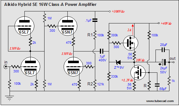
Above is the schematic as it appeared in blog number 58. (Number 58 and this number 110! I am amazed both that so few blog entries have passed and that so many have passed.) If you Google the word “Moskido,” seven pages of links are displayed. Only one link leads to Bob’s amplifier, but it is the first link. As they say in Japan, Ichiban. Great work, Bob.
Audio Note's Feedforward Shunt Regulator
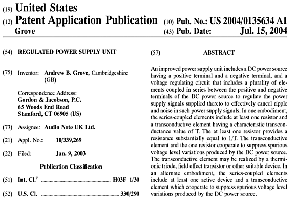
In the above schematic, we see how power supply noise is presented to the triode’s grid, so that it can be amplified and phase inverted at the triode’s plate, effectively nulling all of the power supply noise at the regulator’s output. Unlike the conventional shunt regulator that samples the power supply noise after the series resistor and that can never completely eliminate all the noise, the feedforward shunt regulator can completely null out the noise, as it is not a negative-feedback-based circuit. (Feedback requires that an error exist so that it can counter it. If you think that this sounds a bit anti-causal, you are right, as the feedback system needs an error to be made so that it can unmake it.) A feedforward system is anticipatory; it knows what the error looks like before it appears at the output, so it sends a countervailing signal to cancel the error when it arrives. Try thinking of a negative feedback system as being reactive, not so much in the electrical-engineering sense, but in the current psychological—Seven Habits of Highly Effective People—sense; and think of feedforward systems as being proactive. (See blog 98 for more details.) Now we can move on to Audio Note’s patent. Reading the patent abstract, one gets the idea that they have patented all feedforward shunt regulators. Is that possible? I imagine it all depends on how accomplished your lawyers are and how lame both the Patent Office and the jury are.
I do know that if you did a web search for shunt regulators back in 1997, you would have found Wenzel Associates’ website and the following schematic:
This schematic and two others along with some excellent circuit explication can still be found at www.wenzel.com/documents/finesse.html The patent-busting sentence found there is:
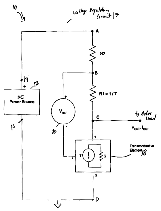
But then, what do I know of the limitless subtleties of the Law? I do, however, know a tiny bit about feedforward shunt regulators. So let’s move on to Audio Note's grand invention:
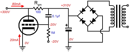
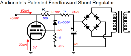
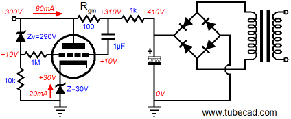
The interesting part of this circuit is the use of a voltage reference to relay the power-supply noise to the input of the active shunting device (it doesn’t have to be a triode; it could be a transistor or MOSFET or pentode). This voltage reference along with an additional series resistor allows the feedforward shunt regulator to establish a fairly steady DC output voltage, something which the feedforward shunt regulator shown above cannot do. If the above patent schematic is too abstract for you, here is one possible implementation.
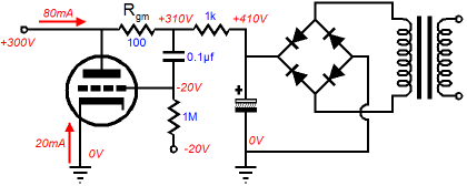
Series resistor, Rgm, 100-ohm value equals the inverse of the triode’s transconductance, 1/gm; thus, we know that the triode has a transconductance of 10mA/V, or put in Siemens, 0.01. the load draws 80mA and the triode draws 20mA, bringing the total to 100mA, which against the 100-ohm resistor equals a 10V voltage drop and against the 1K resistor, a 100V drop. If the regulator’s output voltage strays from 300V, the DC shift is relayed to the triode and it increases or decreases its conduction to counter the shift. I know that some readers are troubled by the extra series resistor and zener. But the following feedforward shunt regulator would work just the same in AC terms.
Altogether, not a bad design (Audio Note’s regulator that is). As you might expect, I would do it a bit differently, as I do not like passing AC signals through zener diodes and I would prefer that the zener relay the regulator’s actual output, not what happens on the other side of resistor Rgm.
Note that the DC error signal is fed to a negative feedback system, while the AC error signal is fed to a feedforward system. Of course, I know that the negative power supply is a bit of a drag, but there is no reason that we cannot use cathode bias instead.
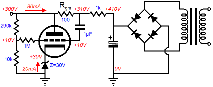
Of course, the zener that takes the cathode resistor’s place can (and should) be bypassed with a large-valued capacitor. The more interesting question is: Why wasn’t a cathode resistor used? Tighter DC regulation is the answer, as the two zeners maintain fixed voltage drops, so that the triode sees the largest DC error signal possible. Alternatively, just using a zener at the triode’s cathode also results in less DC error signal making it to the triode’s grid.
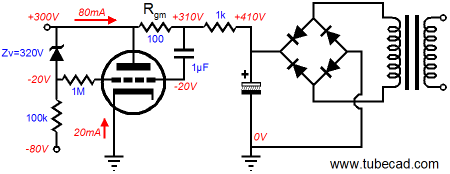
In the above circuit, any DC error on the output is voltage divided by 30:1; for example, a 3V error is reduced to a 0.1V error at the grid. (Here is a thought experiment: replace the bottom 10k resistor with a 1mA constant-current source. What is the voltage division now?) In contrast, with the two zeners, we get the full 3V error. Still, I would prefer the negative-bias version, as it would allow easy idle current adjustments to the shunting triode. If only it didn’t require a negative power supply… Who says that we need a stinking negative power supply?
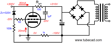
In the above schematic, we see that the 1k series resistor has spun around to the bottom of the circuit, connecting to ground and what is now effectively a negative power supply voltage. Magic? No, not really, just electrical relativity. Ground is where we say it is. (Did you know that if you visit your local electronic store and ask where they keep the high-quality grounds, they will just blankly stare at you?) The August 1999 and December 2000 issues of the Tube CAD Journal hold articles on electronic relativity, which might prove helpful. Now there are two ways of looking at the above circuit: it can be seen as a simple cathode follower circuit, the zener setting the DC output voltage and the cathode simply following; or, it can be viewed as shunt regulator, with the triode’s plate pulling and letting go of the floating power supply, as it strives to maintain its specified DC output voltage. By the way, I hope no one thinks that I am poking fun at Audio Note. In fact, I am quite tickled by the discovery that they are using a feedforward shunt regulator. You see many of my friends are irked by my overly cerebral take on tube electronics. These friends believe tube audio is only art, not science; that it draws only on emotion, not reason. Theirs is a truly romantic viewpoint that sees no need for formulas, calculation, and measurement. And I know that they believe that Audio Note is the premier practitioner of audio artistry, unbesmirched by rational thought and unsullied by careful analysis. So, finding that Audio Note is using the same technical approach that I favor to design their products, must be a huge disappointment. My God, did you know that their patent is filled with formulas? How their feet must be made of clay—it’s like someone saying that John Edwards, the prettiest presidential candidate, really doesn’t weep at night for the poor of America.
//JRB
|
Now accepting Only $19.95
Download or CD ROM www.glass-ware.com
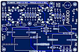
High-quality, double-sided, extra thick, 2-oz traces, plated-through holes, dual sets of resistor pads and pads for two coupling capacitors. Stereo and mono, octal and 9-pin printed circuit boards available.  Aikido PCBs for as little as $24 http://glass-ware.stores.yahoo.net/
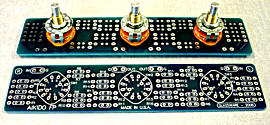
The TCJ Stepped Attenuator The center knob controls both channels, and offers six large decrements; the flanking knobs offer six fine decrements for each channel, creating a volume control and balance control in one easy-to-use stepped attenuator. This clever attenuator uses fewer resistors (only 32) than would be expected from a conventional 32-position stepped attenuator, as two series attenuators would need a total of 72 resistors; and two ladder attenuators would require 140 resistors. In addition, the PCB holds dual sets of resistor pads, one wide and one narrow, so that axial (composition, wire-wound, and film) and radial (thick-film and bulk-foil) resistors can be used without extra lead bending. Although designed to go with the Aikido amplifier, it can be used anywhere a high-quality attenuator is needed, whether passive or active. For example, it would make a first-rate foundation to an excellent passive line box. Visit our Yahoo Store for more details: http://glass-ware.stores.yahoo.net/
The Tube CAD Journal's first companion program, TCJ Filter Design lets you design a filter or crossover (passive, solid-state or tube) without having to check out thick textbooks from the library and without having to breakout the scientific calculator. This program's goal is to provide a quick and easy display not only of the frequency response, but also of the resistor and capacitor values for a passive and active filters and crossovers. TCJ Filter Design is easy to use, but not lightweight, holding over 60 different filter topologies and up to four filter alignments: While the program’s main concern is active filters, solid-state and tube, it also does passive filters. In fact, it can be used to calculate passive crossovers for use with speakers by entering 8 ohms as the terminating resistance. Click on the image below to see the full screen capture.
Tube crossovers are a major part of this program; both buffered and un-buffered tube based filters along with mono-polar and bipolar power supply topologies are covered. Available on a CD-ROM and a downloadable version (4 Megabytes). |
|||


| www.tubecad.com Copyright © 1999-2007 GlassWare All Rights Reserved |