| John Broskie's Guide to Tube Circuit Analysis & Design |
Aikido Variations
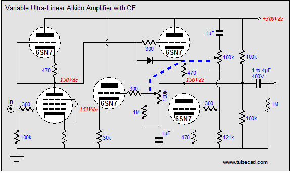
Ultra-linear Aikido 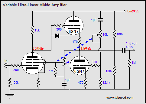
In the schematic above, we see the pentode input tube split the B+ voltage, just as the two triodes do in the classic Aikido topology and we see the output stage also splitting the B+ voltage. Turning the dual potentiometers will not change these voltage relationships by too much. But it will change the amount of pentode plate signal that is fed back to its screen and the amount of power-supply noise that is fed back to the output stage’s bottom triode’s grid. On one extreme of the potentiometer’s travel, we get the following circuit, in which the all the plate signal is returned to the screen and the full 10K potentiometer resistance is presented to the power-supply noise divider circuit.
Effectively, the pentode has been transformed into a triode. The 10K potentiometer resistance and the 12.1k resistor voltage divide the power supply noise to the right amount for the 6SN7 to cancel the 50% of the power supply noise presented by the triode-connected pentode input stage. 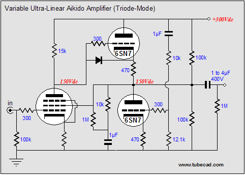
At the other extreme, we effectively get the alternative circuit, shown below, wherein none of the plate signal is returned to the screen and all of the power-supply noise is presented to the output stage’s bottom triode’s grid. The pentode remains a pentode, as its screen is effectively grounded through the 1µF capacitor. Virtually, all of the power supply noise will reside on the pentode’ plate and the output stage will have to null it at its output by seeing all of the noise at its bottom triode’s grid. (Actually, 100% of the power supply noise is not enough to null the noise, but the pentode will not completely pass all of the noise in the first place, so that the output may work out to be power-supply noise-free nonetheless.) 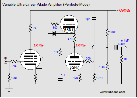
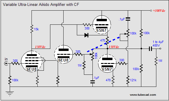
In between these two extremes, ultra-linear operation obtains. What is the optimal ultra-linear ratio? 10%, 17%, 33%, 50%? No doubt that many have an answer, but I doubt that any two will agree on what it is. I believe that, instead of one absolute ratio, each recording and each mood will have its preferred ratio. So, is this circuit perfect? A better question is "Are there any interesting variations on this theme?" Indeed there are. The 10K potentiometers forced us to use larger valued capacitors in the circuit and the potentiometer that feeds the pentode’s screen will see current flow through its scraper (never a good idea, unless the potentiometer was designed with that in mind). Additionally, adjusting the potentiometers will move the pentode’s plate voltage about a tad, as the screen voltage will climb and fall based on its potentiometer’s position. One workaround is to use a cathode follower to drive the screen. Screens like to see low-impedance sources and the cathode follower provides one. Furthermore, the cathode follower’s input is extremely high-impedance and it will not draw current from its potentiometer, while it presents a steady DC voltage. But doesn’t adding a cathode follower mean adding an extra tube? Not necessarily, as many pentode-triode tubes exist, which hold both tub types in one envelope; for example, the 6AN8 and 6EU8.
Of course, with one tube that holds both a pentode and a triode we get what is prepackaged, whereas using two tubes would allow us more options. The following variation uses an extra triode to create a plate load for the pentode along with the triode needed for the cathode follower that drives the screen. Well our tube count went up; but we like tubes, don’t we? In this circuit variation, the output stage’s top triode is protected from seeing the full B+ voltage on its grid at startup, when the pentode is cold and not yet conducting, as the load-defining triode must also heat up first. In addition, the triode load will probably result in lower distortion, as the triode is probably close to being complementarily non-linear to the pentode.
What's wrong with this idea? One problem might be too much gain in the pentode mode. Another problem might be the screen's maximum voltage being exceeded.
Now for something really important
But where do we plug in the tubes? For more details click here.
Next time //JRB
|
Help keep the
The Tube CAD Journal's first companion program, TCJ Filter Design lets you design a filter or crossover (passive, solid-state or tube) without having to check out thick textbooks from the library and without having to breakout the scientific calculator. This program's goal is to provide a quick and easy display not only of the frequency response, but also of the resistor and capacitor values for a passive and active filters and crossovers. TCJ Filter Design is easy to use, but not lightweight, holding over 60 different filter topologies and up to four filter alignments: While the program’s main concern is active filters, solid-state and tube, it also does passive filters. In fact, it can be used to calculate passive crossovers for use with speakers by entering 8 ohms as the terminating resistance. Click on the image below to see the full screen capture.
Tube crossovers are a major part of this program; both buffered and un-buffered tube based filters along with mono-polar and bipolar power supply topologies are covered. Available on a CD-ROM and a downloadable version (4 Megabytes). Download or CD ROM
|
|||


| www.tubecad.com Copyright © 1999-2005 GlassWare All Rights Reserved |