| John Broskie's Guide to Tube Circuit Analysis & Design |
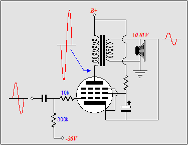
07 June 2006 Tube Power Buffers  The solid-state, unity-gain power buffer is easy to imagine, as many already exist. But what about corresponding tube equivalents? Have they been made? Could one be made? Actually, super cathode followers (complex-and-augmented cathode followers with a gain of 0.99) have a long history, with many interesting designs appearing in the 1940s and 1950s. But a tube power buffer robust enough to drive directly loudspeakers is rare, and with good reason: the impedance mismatch can only be easily addressed with an output transformer. Because of the transformer’s phase shifts, however, the amount of feedback that can be wrapped around a tube amplifier and its output is limited. And all buffers use some form of feedback to deliver low distortion and output impedance. Couldn’t an OTL tube-based power buffer be created that would allow much greater amounts of feedback to be used? Sure; but it, like all tube OTL amplifiers, will be a beast. Transformer-coupled power buffers In the schematic above, we see a power pentode configured in a simple single-ended topology, with the only interesting twist being the pentode’s cathode direct connection to the transformer’s secondary. This connection eliminates the pentode functioning as an amplifier, as the cathode follows the grid, thus providing 100% degenerative feedback. This short feedback loop gives the pentode’s output stage a low impedance output that it would otherwise be altogether lacking. It also lowers the distortion, improves the PSRR, and extends the bandwidth. Actually, the PSRR is fairly good in a pentode-based single ended amplifier, even without the feedback loop, as the pentode’s high rp, unlike the triode’s low rp, makes a poor voltage divider against the output transformer’s primary impedance. In the schematic below, we can see the noise relationships throughout the power buffer. 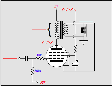
Then we must ask ourselves which pentode to use and how many of them. The KT88/6550 and EL34 are obvious choices, but there are many more pentodes that would work well in this application; for example, the WE350, EL84, 6L6, EL509, KT99 and many others. With a KT88/6550 configured as pentode, an easy 10W could be had per tube (a triode-connected KT88/6550 would yield only half as many watts). The hard part would be in providing enough clean input voltage swing to drive the pentode to its full output. Remember, we are returning the output stage’s output to the cathode, so the input drive voltage must exceed the loudspeaker’s voltage by at least the bias voltage used. For example, if the pentode sees a peak output into the loudspeakers of 16V and a -30V bias voltage, then the input signal to the pentode’s grid must be at least 46V to get to a zero cathode-to-grid voltage. In other words, do not expect your iPod to be able to drive this power buffer directly. (In fact, it is hard to see how any unity-gain buffer with a gain of only 0.35 can go by that name.) However, with an Aikido line amplifier that holds a 12AX7 in the input tube position or just about any high-gain tube circuit, it should be possible to drive the pentode to full output, even with the iPod. If we desire a lower output impedance, then a higher-transconductance pentode or higher winding-ratio transformer could be used. For example, a pentode with twice the transconductance (or two of the same pentodes in parallel) would yield half the output impedance. Beyond these two measures, there is little that we can do with a single-tube output stage.
Complex tube power buffers 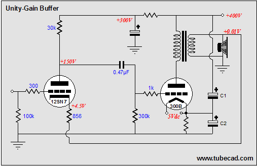 The schematic above shows a 300B being driven by a 12SN7 (yes, a 6SN7 will work just as well). The 12SN7 will realize a gain of 10 in this circuit. So how is it possible to drive a 300B with so little gain? Pause, pause, and pause. The answer is that the input signal that the 12SN7 sees is not the usual 1 to 2 volts, but something closer to 25 volts (to realize an output signal to the loudspeakers of 16 volts). Here’s how the math works: the 300B might need +/-75V to be driven to full output; so the 75 signal is divided by the input tube’s gain, 75/10, which equals 7.5V, which then must be added to the 16 volts that the loudspeakers sees, for a total of 23.5V. In other words, we get nothing for free and the buffer only uses a moderate 20dB of negative feedback, so nothing is being stretched or stressed in this buffer/amplifier. Now that I have a seed circuit, the permutations sprawl across my drawing pad. The first thing that I see is that the simple RC filter that feeds the input stage has to do a lot of work. So, let’s unburden it a tad, by giving it a constant current draw, which can be done in two similar ways. The first is with a cathode follower that uses a cathode resistor equal to the grounded-cathode amplifier’s plate resistor. 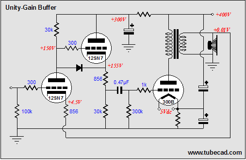
The second approach is to use a cathode follower, but not to use it to drive the 300B’s grid. Why not? Well to some, two stages are not as pure as one stage. For others, cathode followers are creepy in general. So, if the cathode follower isn’t driving anything, what is it doing in this circuit? It is matching the input stage’s current variation. But in current anti-phase, so that net current variation is zero (or close enough for high-end audio work). In either circuit, the power supply decoupling capacitor has much less work to do. 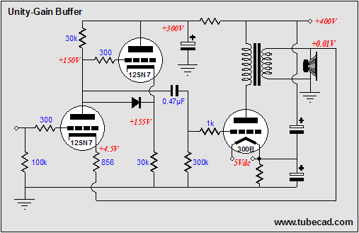
The next thought that comes to my mind is that the input stage’s plate resistor can be replaced by the other half of the 12SN7. Why? Triodes are not perfectly linear, but resistors come close, so a non-linear load is better than a linear load, if that non-linear load is the symmetrical inverse of the triode. 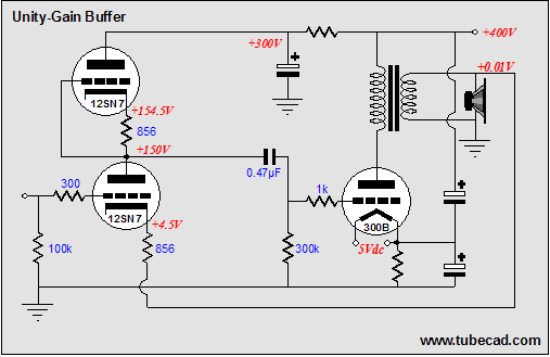 I know that many are thinking that I now will show an Aikido front-end in this power buffer. I won’t, as I am sure that several readers are growing tired of looking at that topology, so I leave it to you to imagine it. (I think the schematic above leaves enough room to make that easy.) Many more circuits are possible. For example, a push-pull tube power buffer, but it is best to stop here, as my dinner is ready.
Next time //JRB |
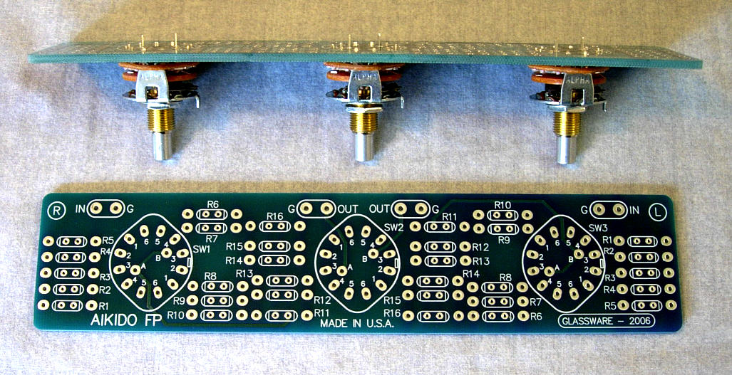 Why Use Stepped Attenuators The TCJ Stepped Attenuator The center knob controls both channels, and offers six large decrements; the flanking knobs offer six fine decrements for each channel, creating a volume control and balance control in one easy-to-use stepped attenuator. The builder must add resistors. Resistors vary in quality and in price; some go for as much as $12 each. Fortunately, this clever attenuator uses fewer resistors (only 32) than would be expected from a conventional 32-position stepped attenuator, as two series attenuators would need a total of 72 resistors; and two ladder attenuators would require 140 resistors. (Resistors, like capacitors, are the objects of hot debates, where one audiophile’s “rich tonality” is another’s blurry and bloated mess, and one audiophile’s “clarity” is another’s cold and harsh stridency; so, I have left the choice up to the individual. But really, any type of resistor in this attenuator will make a better sounding volume control than even the best potentiometer.) Although designed to go with the Aikido amplifier, it can be used anywhere a high-quality attenuator is needed, whether passive or active. For example, it would make a first-rate foundation to an excellent passive line box. Designed by John Broskie & Made in USA Visit our Yahoo Store for more details: | |||


| www.tubecad.com Copyright © 1999-2006 GlassWare All Rights Reserved |