| John Broskie's Guide to Tube Circuit Analysis & Design |
03 August 2005 
Aikido PCB update ...Mission control, all systems are go.
Enough readers—in fact, many more than I expected—e-mailed me to express their desire for PCBs for the Aikido amplifier that I have no fear in placing a large order. As for the PCB layout and choice of tube type, exactly half of you want octals and the other half want 9-pins (in fact, one reader wants loctals). Oddly enough, no one ever asks for 7-pin compatibility, although there are several cool 7-pin, single triode tubes that could work well. The solution I have come up with is to make a PCB that can work with any set of tubes, octals, 9-pin, 7-pin... Thus, if you grow tired of the 6SN7 sound, you can try 5687s or even 12B4s instead—without ditching the PCB. This is made possible by separating the tubes from the PCB by giving the tubes their own formed-metal, socket-holding assembly (or a box chassis that holds four tube sockets on top could be used). I love the flexibility and see several other uses for the tube-socket assembly; a four-tube phono preamp, for example. I should mention that the Tube CAD Journal isn’t the only place to buy a PCB for the Aikido amplifier, as a fellow at diyaudio.com has laid out a PCB and he is looking for customers. His board looks professional, if a bit too tight (I like more room between the tubes and more room for a wider coupling capacitor selection). Additionally, Brian Cherry of diyhfisupply.com tells me that he plans on coming out with a complete kit based on the Aikido circuit. As for my PCB design, I have added a cool feature (no, it’s not the sonic width control) to the PCB that should make the Aikido amplifier your music collection’s best friend. Details to come. Furthermore, I have also laid out a stepped attenuator (36 position) and an input-selector PCB that can optionally be bought. In fact, I plan on offering a nice-looking chassis (and set of knobs) to house all the parts except the power supply, which will have its own enclosure and PCB. (A circuit this good deserves an equally good-looking enclosure.) When, when, when? I am planning on doing a completely thorough review on the Aikido-amplifier PCB before sending it into the PCB house.
Cathode follower output stage design Paying up front 
[A note on high-voltage in general: I hate it. I wish vacuum tubes only needed a few cathode-to-plate volts to pass a few amperes of current. Unfortunately, hundreds of volts are needed to pass just a few hundred milliamps of current. So, the idea of adding more B+ voltage to amplifier is a scary prospect, as the danger increases with the square of the voltage difference, for example, twice the voltage, four times the wallop. Thus a few rules should always be followed when dealing with high-voltage:
I used to take comfort in sitting on a bamboo chair that rest upon a rubber mat with one arm behind my back. Today, I would add eye protection and maybe some test leads tapped to chopsticks.] Just as with any other power amplifier, we start at the end. First we specify a load impedance, output tube type, B+ voltage, and idle current and then we determine what IV relationships the amplifier must undergo and then we resolve what input signal the cathode follower’s grid needs to see to realize those dynamic voltage and current swings. Of course, for many this task would only slightly less daunting than designing a radar system; for these readers, the answer is to cheat and look at someone’s else’s homework: tube manuals often list a design example for the power tubes. For example, the RCA RC-20 tube manual describes a 2A3-based, class-A amplifier (i.e. a single ended amplifier) that works into a load impedance of 2,500 ohms and 250V plate voltage and a negative bias voltage of –45V, which yields an idle current of 60mA and 3.5W output. 2A3 Class A Amplifier We can backward engineer this data into the required IV relationships. For example, 60mA against 2,500 ohms equals 150V, which means that plate will have to swing down to 100 volts at full conduction (250V - 150V) and up to 400 volts at cutoff (250V + 150V), a peak-to-peak plate swing of 300V. The require plate swing becomes the required cathode swing in a cathode-follower, single-ended amplifier. Thus, if the cathode must swing +/-150 volts, the grid needs to see +/-195 volts of swing, which means that the driver stage’s B+ must sport at least a +500V rail voltage in the form of a mono-polarity power supply or +/-250V in a bipolar power supply to fit such large voltage swings (the driver stage triode must displace some voltage as it conducts fully). Creating extra B+ voltage
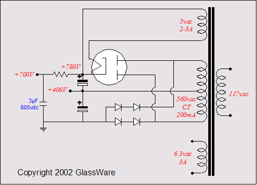
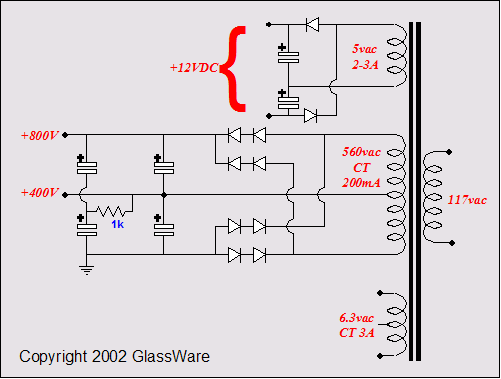
In the schematics above, we see both tube and solid-state rectifiers used to create two B+ voltages (or a positive and negative power supply voltages). The mono-polar and bipolar topologies differ only in where we place ground. When ground is attached at the transformer center tap, we have created a bipolar power supply; attached at the most negative point, a two B+ voltage power supply. If the power transformer doesn't hold a center tap, then the circuit below can be used. It requires an additional four rectifiers and two extra capacitors.
Returning to the RCA tube manual’s design example, the plate voltage was specified at 250V, not the B+ voltage, as all output transformer primaries hold a DCR that will displace some of the B+ voltage; and cathode biasing would also steal 45V from the B+. Thus, a B+ voltage of 300V might be needed to yield 250 across the 2A3. This means that the two-voltage power supply would hold a +300V and +600V tap; the first for the output stage and the second for the driver stage. Alternatively, we could use a bipolar power supply of +/-300 volts. Bipolar power supply front ends
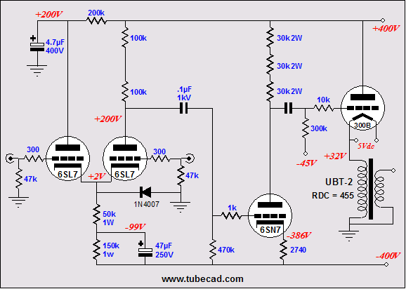
Shown below, we see an input stage and driver stage for a bipolar-power supply, push-pull amplifier. (This circuit could be used to drive electrostatic headphones, which would make for an interesting dual use amplifier.) 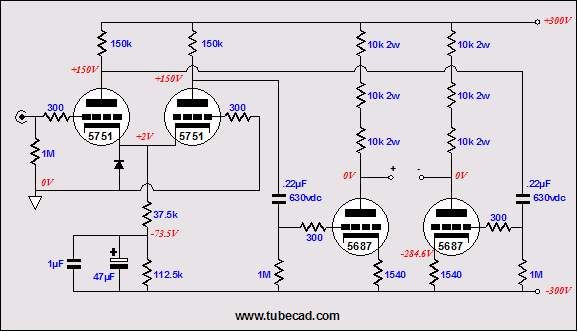
I know that many are thinking that the bipolar power supply would allow DC coupling of the driver stage to the output tube’s grid. Bad idea! What happens if the driver tube fails or is pulled from its socket (or even just jiggled in its socket)? I don’t know how much current a 2A3 would conduct with +300V on its grid—probably, something close to 1.5A, the result of multiplying its gm against 300V. Furthermore, tubes age and can drift an amazing amount in just a few minutes. How would you adjust the idle current in such an amplifier? One possible workaround is shown below. 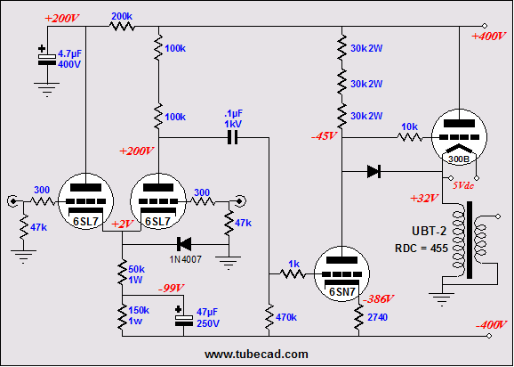
The amplifier below uses a hugely-valued cathode resistor that terminates into the negative rail, not ground. This large cathode resistor will protect the output tube by greatly limiting its maximum current conduction (Imax = V/Rk, which in this example is about 150mA DC). 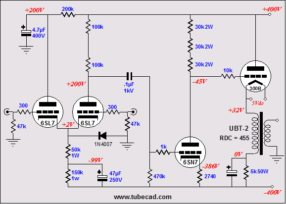 Do not fail to note the 50W cathode resistor. This topology wastes a huge amount of heat just to do away with one coupling capacitor. But was it really eliminated? It seems to me that the electrolytic capacitor is much worse than any coupling capacitor. 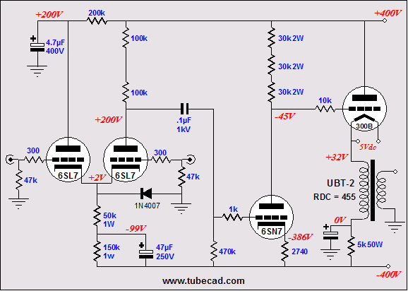
Why not use a low-voltage capacitor to shunt the output transformer to “ground," having capacitor terminate into ground instead of the negative rail? Two problems: what happens when the output tube is missing from action or when driver tube is missing? In the first case, the capacitor becomes reversed biased, which will destroy an electrolytic capacitor, as less than 1 volt of reverse polarity is enough to permanently damage such a capacitor. In the second case, the capacitor will charge up to something close to the B+ voltage, which means that a low-voltage capacitor cannot be used after all. Next time //JRB |
Only $12.95
Download or CD ROM www.glass-ware.com
|
|||


| www.tubecad.com Copyright © 1999-2005 GlassWare All Rights Reserved |