| John Broskie's Guide to Tube Circuit Analysis & Design |
15 July 2005
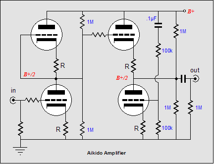
Aikido amplifier
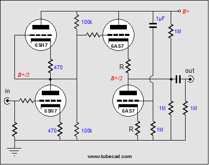
Here’s an analogy: you have a great interest in water-color paintings and you hold that the paint’s hue and saturation are all important and that those who claim a perfectly white canvas is of primary importance as it will allow the true colors to remain true are clueless technocrats. A good PSRR figure means that the amplifier is able to work around the power supply’s imperfections—main frequency hum and rectifier ripple are only two possible power supply failings. The power supply can pollute in more than just these two ways; it can re-circulate the signal from the output stage back into the input and driver stages and then back again… And it may fail to work as intended at only low or only high frequencies, by deviating from being low impedance to being high impedance, any of which may occur in the absence of hum or ripple. The Aikido circuit sidesteps the power supply failings by including them in its normal operation. Additionally, the Aikido circuit symmetrically balances imperfect triodes against equally imperfect triodes, which greatly reduces its distortion output. The result of these two features is an effortless and natural sound that is hard to improve upon. In general, I have been trying to paint in broad brushstrokes in this journal. Paradoxically enough, this journal seem to have two types of readers: those who are utter tube novices and those who are complete tube—priests, cardinals, bishops, popes—which best describes some one who, if required, could recreate on his own great chunks of the Radiotron Designer’s Handbook? Why so few in the middle? My guess is that these audio sophomores simply know all there is to know already, whereas the beginner realizes that he knows little and the expert realizes that, in reality, very little is known by anyone. Thus, my broad brush strokes: those who are starting out will not get lost in long equations and those more accomplished can derive the equations on their own. (Besides, for many, the whole point of tube audio is that it supposedly falls out of the scope of analytic reasoning, being more like magic than engineering.) However, I believe the Aikido circuit needs a bit finer stroke now that it seems more familiar. The broad-stroke explanation of the Aikido amplifier was that the circuit eliminated power-supply noise from the output, by injecting the same amount of power-supply noise into the top and bottom of the two-tube cathode follower circuit; that the input stage (the first two triodes in series with each other) defines an AC and DC voltage divider of 50%, so that 50% of the power-supply noise is presented to the top cathode follower’s grid, while two equal-valued resistors in series also define a voltage divider of 50%, which feeds the bottom triode's grid the same 50% of the power supply noise. Since both of these signals are equal in amplitude and phase, they cancel each other out, as each triodes sees an identical increase in plate current, so the output remains steady in spite of the power supply voltage fluctuations. All in all, this explanation is accurate, as long as the triodes used have a relatively high mu, say at least 20, as the two triodes in a dual-triode tube are seldom matched better than 5% (the reciprocal of 20). Even dual triodes made with tight matching of triodes in mind, such as the 6SU7, are seldom better than 3% matched. However, this explanation loses accuracy with a low-mu triode, such as the 6AS7, as the top and bottom triodes used in the cathode follower stage require dissimilar percentages of power supply noise to produce a null at the output. Here’s why. The aim was to provoke an equal current increase and decrease in top and bottom triodes in the output stage to produce a tie, wherein neither triode wins in its tug of war with the other triode. And supplying high-mu triode with equal grid-to-cathode input signals pretty much ensured an equal current modulation in the face of power supply noise. With low-mu triodes equal input signals are not enough, as the triode’s rp will create its own current modulation in the face of power supply noise. This extra current conduction will unbalance our tied tug of war, as the extra conduction will only occur in the top triode of the output stage. Let’s use an imaginary triode with an rp of 1 ohm, a gm of 1A/Volt, and a resulting mu of 1. Feeding 0.5 volts of power supply noise into the bottom triode will provoke a current change of 500mA, with its cathode-to-plate voltage held steady, as we have nulled the noise at the output. Now, 0.5 volts of power supply noise into the top triode’s grid will also provoke 500mA of conduction variation, but the top triode’s rp of 1 ohm will provoke 1A worth of conduction variation, as it sees all of the power supply noise on its plate. In other words, the bottom triode would have to see an input signal great enough to counter the top triode’s 1.5A worth of current conduction change in the presence of 1V of power supply noise. Since the gm was 1A/V, 1.5V of power supply noise would be needed to match the top triode’s conduction change. The formula for the optimal ratio of power supply for the bottom tube is Ratio = 1/mu + ½ As you ca readily see, the greater the mu, the closer the ratio gets to 50%. But with a tube like the 6AS7, with a mu of 2, the needed ratio becomes ½ + ½ = 1 or 100%. Thus an Aikido amplifier with a 6AS7-based output stage should look like this:
Notice the missing voltage divider; all of the power supply is presented to the bottom triode’s grid. A 6BX7, with a mu of 10, would require a ratio of 60%, which could be made from 40k and 60k resistors in series. A reader from Genova University in Italy, Federico, e-mailed a nice formula for specifying the bottom resistor’s value, once the top resistor’s value has been established: Rbottom = Rtop x (mu + 2)/(mu –2) Another fine brush detail in the Aikido amplifier’s explanation is the role the safety resistors play. In the circuit at the top of the page, the two 1M resistors serve two purposes: the first is to protect the output stage from having the input stage tube pulled from the circuit by providing the same B+/2 voltage to the output stage’s top triode’s grid. The second purpose is to help burn some gain without penalty. Extra loading on a triode usually only adds distortion, but not in this circuit. Because the top and bottom input stage triodes are equally burdened, the Symmetry God smiles upon the Aikido amplifier. In fact, at least in SPICE simulations, choosing the right resistor values can even lower the distortion of the Aikido amplifier. By specifying the right valued resistors, a sizable decrease in distortion can be realized (a "realized simulation," an interesting description). However, here's the problem with trying for too much in SPICE: the tube models stink and they are perfect. They do not resemble actual tubes and the models are perfectly matched, which real tubes are not. Still, if you can get a -60dB improvement in SPICE, you can probably get an easy -20dB improvement in reality.
Printed circuit boards for the Aikido amplifier Next time //JRB |
Support the Tube CAD Journal & get an extremely powerful push-pull tube-amplifier simulator for TCJ Push-Pull Calculator
TCJ PPC Version 2 Improvements Rebuilt simulation engine *User definable
Download or CD ROM For more information, please
visit our Web site : To purchase, please visit our Yahoo Store:
|
|||


| www.tubecad.com Copyright © 1999-2005 GlassWare All Rights Reserved |