|
(Current into 0 ohms equals 0 volts, which is why the scope could not see the DAC's output.) But an Op-Amp's inputs cannot source or sink any current (this is the ideal behavior and is close to being true for the FET- or MOSFET-input-based Op-Amps). So how does the negative input mimic ground? If the Op-Amp is configured as a unity gain buffer with the output directly fed into the negative input, then the output stage sources or sinks any current, thus making the negative input appear as a ground connection. And if negative input and output are indirectly connected through a resistor, the output stage still does all the work. The only difference is in this case that output stage must compensate for the voltage drop across the resistor. So here is the beauty of the circuit: an I-to-V converter uses all its gain to keep the input at 0 volts (and thus 0 ohms) and uses the voltage developed across the resistor to define its output voltage. For example, an I-to-V converter with a resistor of 1k sees a 1 mA input current, which it counters by moving its output 1 volt. If it moved more than 1 volt, the input would not be at 0 volts, as the resistor bears 1 volt across its leads; conversely, if it moved only .5 volts, the input would also fail to be at 0 volts. In other words, the only way the Op-Amp's inputs can match each other is when the output moves to the voltage appropriate to offset the voltage drop across the resistor that results from the input current flowing through that resistor. To increase the conversion ratio (not the gain) increase the resistor's value. (Yes, a potentiometer would allow trimming.) The latent paradox is How can an amplifier that has both its inputs shorted to ground amplify any signal? It can't, is the quick answer. The longer answer is that some small voltage signal must be present at the negative input. How small? The output voltage divided by the open loop-gain of the Op-Amp is roughly the answer. The exact answer is the output voltage divided by the sum of the open loop-gain plus 1. And since Op-Amps usually run open-loop gains up to the millions, very small indeed is the better answer. In fact, the lazy assumption usually made is that Op-Amp has infinite gain, as millions is effectively infinite. (The truth is that all Op-Amps have a finite gain and one that usually falls off at -6 dB per octave after reaching some corner frequency, which can be as low as 10 Hz. Fortunately, the Op-Amp's gain is usually so great that even at 20 kHz there is plenty of gain and hence feedback available.) |
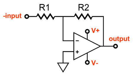
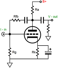
One critical point to be made here is that the current source feeding the I-to-V converter must have a near infinite output impedance. If an Op-Amp is directly used to feed the I-to-V converter, one or both Op-Amps will die in the fight. Placing a resistor in series with the first Op-Amp's output solves this problem. Any output voltage will develop a proportional current into this resistor, as its other end is effectively grounded by the I-to-V converter input. This current is then converted to voltage by the I-to-V converter. Wait a second, do you mean to say that a simple inverted Op-Amp topology is actually made up of a V-to-I converter feeding an I-to-V converter? Yes, I do; the resistor is effectively a V-to-I converter cascading into an I-to-V converter. Why don't other people refer to it this way? Part of the answer lies in mental rut so many have fallen into: of thinking primarily in terms of voltage. I was broken of this habit when I designed an amplifier to drive .5 ohm ribbon speakers. The output voltage was miniscule and the output current was staggering (10 amps for 25 watts). Tube I-to-V Converters Can an I-to-V converter be made from vacuum tubes? (Well if it couldn't, this subject probably would not be covered in this journal.) Certainly one can be made and with as little as one triode and a few passive parts. Just placing a resistor in series with the coupling capacitor of the virtual resistor example transforms our virtual resistor into an I-to-V converter. But let's look a little more closely at how an I-to-V converter must be used to function well.
While adding the series resistor, Rfb, did create an I-to-V converter, driving this converter or any other feedback I-to-V converter with a voltage source will undermine the results. For example, if a low output impedance amplifier feeds the input of this I-to-V converter, the output of this converter will not be proportionally related to the input current, as the converter's output will only equal the gain of the tube when loaded down by the plate resistor shunted by Rfb's value and the output impedance only equals the rp in parallel with these resistors, as all the feedback has been removed. |
|
| www.tubecad.com Copyright © 2001 GlassWare All Rights Reserved |