| Subject: Circuit Help I have been experimenting with amps to drive the bottom end of my system (yes the OTL that haunts these pages drives the top) and have built the single ended tube/MOSFET as shown on http://digilander.iol.it/essentialaudio/hybrid. I found, as with many other trial setups using transistors to augment tube circuitry, that the sonic signature of the silicon overpowers the tube and that any technical advantage that may be gained is swamped by the transistor's artifacts. The design mentioned above has many features to recommend it and, as you mentioned last month the use of current mirror technology in tube circuits, I now wonder about what modifications are required to convert the solid-state current mirror to a tube based one. I have never seen a tube "current mirror" used in a differential tube amp but they are "state of the art" in transistor land and do wondrous things to linearize those circuits, reducing distortion and increasing slew capability. The other query I have is that in all the other reading I have done regarding tubes driving the capacitive gates of MOSFETs the point is always made about requiring a low driver impedance, to enable sufficient interstage bandwidth - thus not limiting slew rate capability. In your suggested single ended hybrid circuit as shown last month (somewhat similar in layout to the circuit mentioned) this does not appear to be an issue. I would have imagined that in this type of hybrid design that the lower output impedance of a SRPP (at the least) or cathode follower would need to be used. Your analysis of the current mirror and the driver impedance issue would be a great help to my tube learning curve. Wayne |
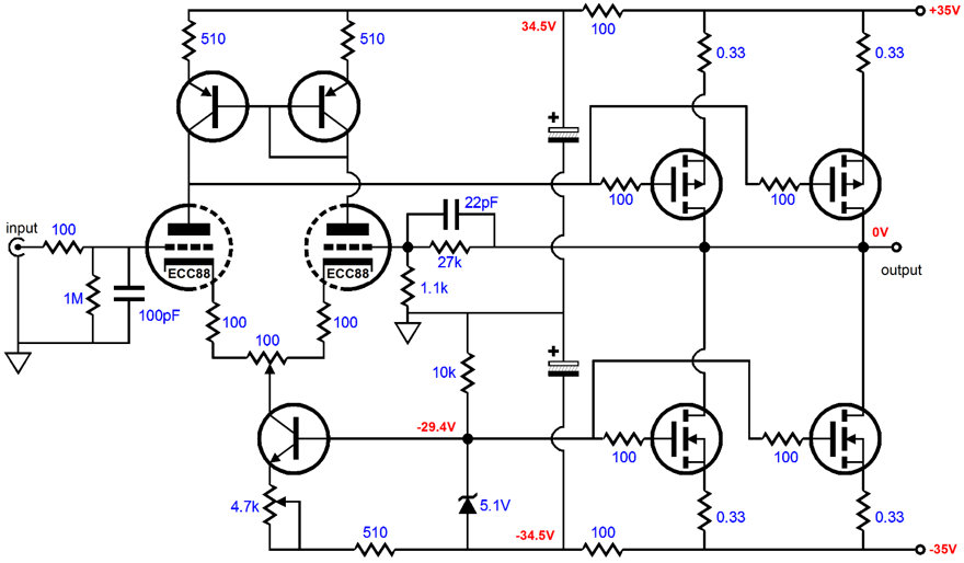
First off, let me thank you for the link, as I enjoyed exploring the circuit. Now, I don't wish to appear disrespectful, but I got a few giggles when I visited the site, as both the advertising copy and circuit design held a few bloopers. But first a quick recap of what I saw: the amplifier is a hybrid design with a tube differential amplifier input stage that finds a transistor current mirror as an active load that then directly cascades into a pair of parallel P-channel MOSFETs (IRF9540), which are loaded by N-channel MOSFETs (IRF540) used as a constant current source. In other words, the amplifier runs a pure Class A, single-ended output stage. And here is where the advertising blooper enters. The power supply rail voltages are ±35 volts, which means if all of the rail voltage could be delivered into the loudspeaker (it can't), the maximum power output would 76 watts RMS, not the 90-100 watts RMS the copy claims. Power = Vpk²/2Rload. Or, if we take the maximum idle current they specify (4A), we end up with only 64 watts RMS. Power = Ipk² x Rload/2. On the other hand, 100 watts RMS requires an idle current of 5A, as the idle current equals the maximum current that can be delivered into a load with a current-source-loaded class-A amplifier. Furthermore, the maximum theoretical efficiency of a current-source-loaded Class A amplifier is only 25%. Now 70 volts against 4A equals 280 watts, which even if we could realize the maximum efficiency of the amplifier (we cannot in reality), the maximum output is limited to 70 watts. This practice of advertising peak or "imaginative" watts as RMS is widespread. My best guess is that manufacturers claim as many watts as they think the appearance of the amplifier suggests. This also seems to be the technique used by transformer makers. For example, if a single-ended transformer is rated as having an idle current limit of 100 mA and a reflected impedance of 3k, what is the maximum possible RMS power into the load? The math is trivial: Power = (Rpri x I²) / 2 In this case, 15 RMS watts is the answer, not the 35 watts advertised. |
|
|
||
| www.tubecad.com Copyright © 2001 GlassWare All Rights Reserved |