| Push-pull output stages are basically difference amplifiers, which is why a phase splitter is needed, as a balanced, push-pull input signal is needed. Presented with the exact same signal, the differential amplifier does not amplify, as there is no difference to amplify. This works wonderfully to reduce power supply noise in a conventional transformer coupled push-pull amplifier, as the noise is common to both phases (or at least we hope it is). The problem with inline push-pull amplifiers, however, is that the noise is not always equally superimposed on the two input signals. This discrepancy gives rise to noise at the output, as it is a difference that can be amplified. Therefore, in order to reduce the noise at the output of an optimally designed White cathode follower, we must ensure equal noise, equal in both amplitude and phase, superimposed on the signal at each grid. Yet we only have one input with a White cathode follower, the top grid, available to us. Just what is the existing noise distribution in an optimally designed White cathode follower? For the top triode, the answer is easy enough: its grid sees whatever power-supply noise is presented by the previous stage's output. But the bottom triode must see half the B+ noise at its grid by necessity. This results from specifying that the White cathode follower's plate resistor equal the reciprocal of the triode's Gm. For example, a +1 volt pulse applied to the B+ will be relayed to the bottom triode's grid. The bottom triode will then fight this positive pulse by increasing its conduction by the +1 volt pulse against its Gm, which in this case is 10 mA/V. Thus, the increase in conduction for both triodes is 10 mA, as both are in series with each other. Now, 20 mA (the 10mA idle current plus the 10mA pulse current) through a 100 ohm resistor equals 2 volts. And as the resistor has just been pulled up one volt, the extra 1 volt developed is displaced by the that pulse. In other words, they cancel, , as +1V - 1V = oV, leaving the top triode's plate voltage unchanged. Wait a minute if the pulse is needed to cancel itself, how can it, once cancelled, work to cancel itself? It can't. The best it can do is tie and leave about half of the pulse present on the top plate and, in turn, present on the bottom grid. Another way of seeing the mechanism at work is to find the effective (not the nominal rp) impedance at the top triode's plate and then figure out the voltage division between the plate resistor and the rest of the circuit bellow it. Because the coupling capacitor relays the any voltage variation on the top plate to the bottom grid, the effective Gm for the entire circuit is equal to the bottom triode's Gm, say 10 mA per volt. Thus, the inverse of the Gm rougly equals the impedance present; or, in htis example, 100 ohms, as 1/0.01 = 100. |
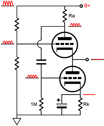
Thus, the effective impedance of the top plate is 100 ohms. Since this 100 ohms impedance finds itself in series with a 100 ohm plate/sense resistor, the voltage division is 50%. (This is an idealized and simplified overview, as the actual Ra resistor value would equal (rp + Rload) / mu, not just rp/mu. But as a 32-ohm headphone driver is effectively close to zero ohms for the triode, we can get away with ignoring it.) So, if we want to match power supply noise on each grid, we must give the top triode's grid half this noise. In the drawing below this end is achieved by using two equal valued resistors—instead of a proper input stage—for illustration purposes.
Assuming that a grounded-cathode amplifier is used for the first and that its cathode resistor is not bypassed by a large capacitor, making the first stage perform this voltage division requires that the plate resistor equal the sum of the rp and the cathode resistor magnified by the mu + 1. Putting this into a formula: Rk = (Ra - rp) / (mu + 1) Obviously, the plate resistor must exceed the rp and the cathode resistor must not be capacitor bypassed. Using the 6DJ8 as an example, a 20k plate resistor should find a 500 ohm cathode resistor to match. Since reality will differ from our expectations and since this Aikido-like technique is very close, but not exactly on target, a 470-ohm or 560-ohm cathode may, in reality, deliver better PSSR figure. |
|
| www.tubecad.com Copyright © 2001 GlassWare All Rights Reserved |