| Tube CAD Journal |
| No doubt, many any a reader is now puzzled by the paradox of stating that a tube's effective impedance equals 120 ohms when its plate sees a several hundred volt power supply. Surely, the tube would melt if it saw the same current that a 120 ohm resistor would experience with 360 volts across its leads (3 amps!)? Like so many paradoxes, this one crumbles when precision of speech is brought to bear on it. "Impedance" is similar to "resistance," but not identical to it. That the two words are often used interchangeably is due to sloppy thinking and that erosion of meaning that all words must bear from use. ("Transpired" once meant more than just "happened" and "nice" once wasn't nice and, while are at it, "Class-A" once meant something other than "Class-AB". When Confucius was asked what he would wish for if given only one wish, replied "I would restore the original meanings to words.") "Resistance" describes the opposition to a flow of DC current; "impedance," the sum of resistance and reactance (the opposition to AC current). Thus, the need to speak of pulses, as adjusting B+ up 1 volt, will only give a momentary pulse in the increase in current conduction before relapsing into a slightly higher conduction because the capacitor will not sustain that 1 volt increase for long.
The DC resistance is found by simply dividing the plate voltage by the plate current. The AC resistance requires taking a small voltage range and dividing it by the resulting range of current swing: AC Resistance = (V2-V2) / (I2-I1) Bear in mind that this is not some trivial and pedantic distinction, as understanding this distinction is necessary to any real understanding tube electronics. A triode has a DC resistance and an AC resistance. Since sound is an AC phenomena, we primarily concern ourselves with the AC aspect of the triode's functioning.
|
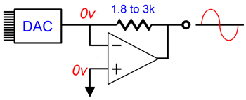
However, an understanding of a tube's DC functioning is essential to figuring out how to bias the triode or making sense of its plate curves. It is truly unfortunate that a tube's impedance is named "Plate Resistance" and not "Dynamic Plate Impedance" or even "Plate Impedance," just as it is sad that there is the conventional description of current flow and the actual flow from negative to positive, but such are the accidents of history. (The triode does not have a reactive component to its functioning other than the minor internal capacitances and inductances, so the best name might be "Dynamic Plate Resistance.") I-to-V StagesSince this circuit is not a voltage amplifier, how do we make an amplifier out of it? Strictly speaking, we don't. What we create instead is a I-to-V (current-to-voltage) converter. This type of circuit receives a varying input current and then delivers a proportionally varying voltage at its output. Everyone who has ever played a CD has indirectly encountered an I-to-V converter, as the output from the DAC inside CD player is a varying current. (Those few DACs that do provide a voltage output contain an I-to-V converter internal to their case.) Attaching a scope probe to the DAC's output reveals almost nothing, as the scope reads voltage not current. Only when the current flows through some impedance or resistance does the voltage developed become readable by the scope's probe. So in order to give amplifiers their required drive voltage, the I-to-V converter is needed.
An I-to-V converter usually consists of just a resistor and an IC Op-Amp. The input to the Op-Amp is taken at its negative input and the resistor spans this input to the output, while the positive input is grounded. Any current flowing into the negative input will have to flow through the resistor, which will develop a voltage across this resistor. Since Op-Amps work to prevent any differences from occurring between their positive and negative inputs, the negative input will effectively mirror the positive input, which means the negative input is effectively grounded as well. | |
| www.tubecad.com Copyright © 2001 GlassWare All Rights Reserved |