| ||
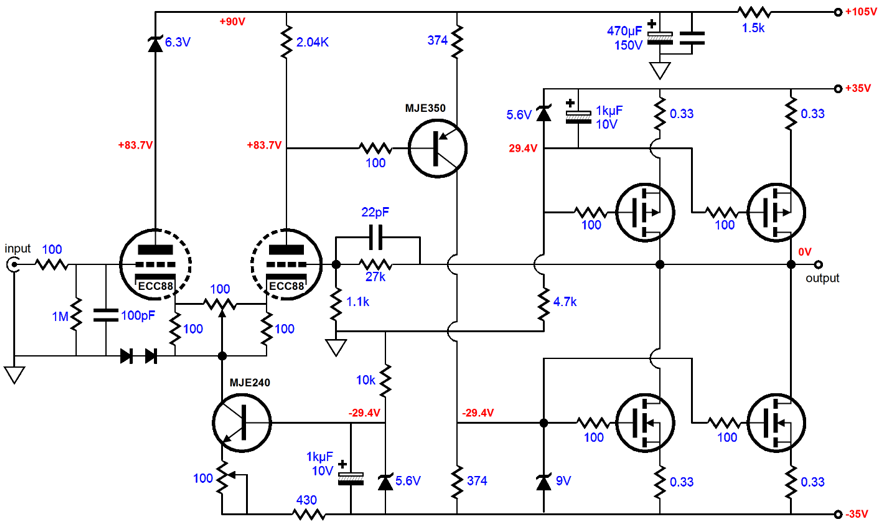
| (I played with Lender's circuit back in the 80s after reading about it from Erno Borbely; the task I wanted to accomplish was to build a DC hybrid line stage that sandwiched transistors in between triodes. The input was a 6DJ8 based differential amplifier and the output tube was a triode connected EL84 used as a cathode follower. The project was abandoned not because of Lender circuit but because I had played with some zero feedback alternatives that provoked a major rethink and this hybrid had lots of feedback. Although, if redesigned, it might make a good article.) Since the input to this circuit is at the top of the amplifier, the output must be taken at the bottom of the amplifier, which means reversing the roles between top and bottom MOSFETs. Something that might be for the good, as I believe that the IRF540 is slightly more linear than the IRF9540. (Actually, if you can source some Hitachi 2SK134s and 2SJ49 all the better. One caution is that these devices are only rated for 100 watts dissipation.) Still, I am not convinced that this is best way to go. Something simpler and less linear might be better. The higher voltage and current are absolutely desirable and should be retained at all costs. So how do we implement something like the plate resistor loading transformation while still retaining DC coupling? Given that you have in this amplifier the answer to most the big hassles of amplifier construction (power supply, heat sinks, and chassis), why not try something quite topologically different. Here then is a complete remake of the amplifier. The circuit shown below meets all our requirements: it uses higher voltages and currents for the tubes and DC coupling throughout. Indeed, the tubes get their higher voltage and higher current; DC coupling is retained and aded safety features are implemented—yet much of the original circuit's components remain in place. (The solid-state current source feeding the tail of the differential amplifier could be replaced with a resistor and a potentiometer. Asides from subtracting active solid-state devices, this allows us an easy means of adjusting of the idle current of the bottom MOSFETs.) And the original potentiometer at the cathodes has been changed to help overcome some of my fear of potentiometers carrying current and signal. |
In this redesign, even if the potentiometer's scraper loses all contact, the output stage is safe, as the two added resistors continue to provide a current path. The amplifier is still DC coupled throughout, as the use of the DC coupled phase splitter reflects the change in current flow through the triode to the output stage. So the output's DC offset can minimized by the feedback. New safety features include having the top bank of MOSFETs shut off, if the bottom power supply fuse blows. And should the top power supply fuse blow, the 105 volt power supply voltage will also collapse, thus indirectly turning off the bottom bank of MOSFETs. Note that the top filter capacitor could be bypassed by a protection diode. This will prevent the capacitor from ever seeing a reversal of polarity should a fuse blow. Remember, as little as 1 volt of reversed voltage is enough to damage an electrolytic capacitor. The problem of keeping the opposing banks of MOSFETs conducting the same amount of current while the tube heats up is solved by carefully choosing the value of capacitor C1. This capacitor is charged through a 4.7kk resistor, which buys us a time delay before the top bank of MOSFETs start to conduct. The aim is to have both banks come online simultaneously and some tweaking will be required. Still, an amplifier that runs such a high idle current makes me nervous and I would use a fault sensing circuit on the output that would clamp the output to ground should anything go wrong. I would seriously look into using a coupling capacitor between the bottom of Lender's circuit and the gates of the bottom MOSFETs, as this would allow the use of a DC servo that would keep the DC offset minimized, even if the input tube were missing from its socket. In addition, it would allow us to use a larger valued resistor, which would yield more gain. It seems to me foolish to forgo the use of a DC servo when it works best, i.e. in the output stage of a Class A amplifier. |
|
|
||
| www.tubecad.com Copyright © 2001 GlassWare All Rights Reserved |