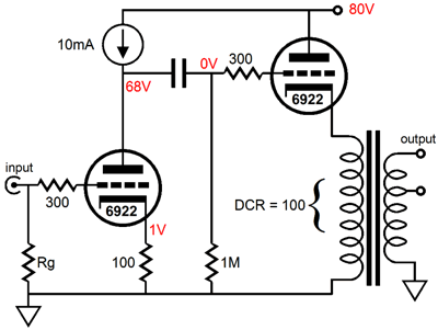
| The final gain of the amplifier is found by dividing the winding ratio (sqrt[Zprimary / Zsecondary]) of the output transformer into the gain at the plate. Assuming that 5k is the reflected impedance, parallel 6922s will have a gain of about 20, which divided by the winding ratio of 12.5 using the 32 ohm tap, yields a gain of 1.6 times the input signal. This seems low, but it might work well, as most of the sources we will use for signal would normally have powered the headphones directly; thus, we do not really need the gain. If more gain is required, then a different tube is needed. The 5687 just draws too much heater current to be used with parallel triodes, but it might work with one triode per channel. The 5687, however, will provide even less gain than the 6922. The 12B4 might sound wonderful, but its even lower low mu makes driving it directly problematic. The problem with using a 12AX7 or 5751 is that these tubes have plate resistances much higher than the 5k primary impedance. And we would like to use something close to the classic ratio of 2rp for a load impedance. The 417A has both a high mu and a low rp, but besides from being hugely expensive, it is often extremely microphonic. One possible choice is the 6AQ8. Used with parallel triodes, it gives us a gain of 29 with the 5k load. You can readily see how using more than one stage greatly reduces our design limitations, but it does eliminate the simplicity of using just a single triode. For example, half of a 12AU7 cascading into a 12B4 would yield both a low output impedance and a fair amount of gain. While three tubes would look cool, one dual triode envelope per channel has its attractiveness as well. Here the cascading of a grounded cathode amplifier into a transformer loaded cathode follower might be the best choice.
So here is a plea to anyone who has access to this transformer from Antique Sounds: please send us some information, such as the DCR for both primary and secondary and where you were able to acquire the transformer. |
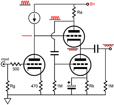
The White Cathode Follower This variation on the cathode follower is actually a push-pull amplifier, as evidenced by the disparity in current phase through top and bottom tubes when driving a load impedance; thus, the pulling and pushing. A small valued plate resistor is used to sense current variations through the top triode and the resulting anti-phase signal is relayed to the bottom triode. The October 1999 issue covered in detail both the workings and math behind this topology. The punch line was that the plate resistor must roughly equal the reciprocal of the Gm of the triodes used, if a balanced drive is to be achieved; or, put more precisely, Ra = (rp + 2Rload) / mu This circuit started this series of articles. In the reply to a reader's questions about this topology, I offered some possible recommendations or rather modifications to a circuit he submitted. Since then I have given the circuit a rethink. I had recommended using a FET based current source to load the first stage to lower the PSRR at the output. This suggestion is not a bad one, as it does afford the greatest gain, which feedback could use to lower the output noise. But it does lack the almost Aikido like noise sidestepping techniques that in this journal. In other words, let's get clever.
Note how the noise-free signal passed to the White cathode follower input is not enough to ensure a noise-free output signal, as the power-supply noise present o the top triode's plate is relayed to the bottom triode's grid. |
|
| www.tubecad.com Copyright © 2001 GlassWare All Rights Reserved |