|
|
Design Idea:
A Constant Power Output Stage
|
|
|
|
|
What if we are willing to accept the price of Class A operation, but we are not willing to have the output tubes plate dissipation exceeded? In other words, how do we achieve a constant power dissipation of the output tubes regardless of the wall voltage's wandering? The answer lies in a slight modification to the auto-bias circuit so that it adjusts the idle current to match the changes in B+ voltage.
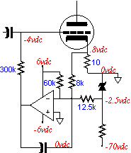
The adjustment of the idle current can be made at either the grid or at the cathode of the output tubes. This circuit adopts the latter option. Auto bias circuits that control the grid bias voltage of the output tubes work by striving to maintain a constant voltage across a resistor in series with the cathode. A constant voltage across this resistor equals a constant DC current. If the voltage reference is not fixed and changes with the changes in the B+ voltage, then the idle current through the output tubes will track the changes in the B+ voltage. Tracking the change in B= voltage can be preformed in two ways. The first is the obvious way: use a large valued, high wattage resistor to connect to the high voltage power supply. The second is to sample a lower voltage power supply that tracks the voltage drift as the high voltage power supply. (This is another reason why Class A operation is essential, as in a Class AB type amplifier the power supply voltage will sag with output signal.) this second approach not only saves on heat it is also safer for the use with solid-state devices. The lower power supply voltages are +/- 6 volts, although just about any voltages could be used.
|
|
|
|
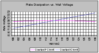
Biasing an output tube can be a hassle: thus the attractiveness of an auto-bias circuit. An auto-bias circuit will maintain a constant idle current in spite of the tubes aging or becoming gas filled or the wall voltage shifting. The limit to ready acceptance of these circuits is two fold. The first is that unless some clipping circuit or some input signal sampling rectification circuit is included, these circuits only work well as long as the amplifier remains in strict Class A operation. In a Class A amplifier, the average current flow while in use equals the idle current, but in a Class AB, or B amplifier the average current flow while amplifying music exceeds the idle current, which precludes using this simple auto-bias circuit. The second is that the plate dissipation of the output tubes may be exceeded when the wall voltage climbs. For example, a 2A3 has a maximum plate dissipation of 15 watts, which would be met with 300 volts from cathode-to-plate and an idle current of 50 mA. However, if the wall voltage were to climb by 10%, then the B+ voltage would climb by the same percentage. Now the 2A3 would see 330 volts and the same 50 mA of idle current, which would put its plate dissipation at 16.5 watts. (This scenario assumes that the power supply is unregulated.)
|
|
|