|
To lower the distortion further means that we are going to have to resort to feedback, as the input stage is much cleaner than the output stage. Thus wrapping a loop back to the input stage means that it can iron out the output stage’s non-linearity. Pawel must be pulling out his hair right now, but we can make a swap: we will use feedback, but will not use the coupling capacitors. The circuit below will confuse many. The circuit is no longer balanced at the output, which is actually a plus, as most headphones come with a standard plug, not an XLR connection. Wait a minute, don’t circlotron type amplifiers have to have a balanced, floating output? No, they don’t. Remember ground is not a physical component that you can buy at Radio Shack, it is a point of reference, nothing more. Yet many speak of “ground” as if it were an electrical black-hole or magical entity. The tubes, resistor, and capacitors are blind to “ground.” All they know is that so much current flows through them or so much voltage is present across their leads. If you name the positive terminal of a 9-volt battery “ground,” then you have a 9-volt negative voltage source; if you name the negative terminal “ground,” a 9-volt positive voltage source. (I have been told that grounds cannot be become polluted or dirty, as a ground is perfect —you know, metaphysically, which is, in fact, true, as long the infinitely small point of chassis or wire that has been christened “ground,” is the only point under consideration, not any of the adjoining atoms of metal, let alone the end of a long, snaking coil of 22-gauge wire.) |
|
More ð |
|
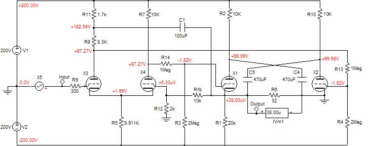
Consider this: grounding the output stage’s second triode does not stop it from working. As its grid sees a varying voltage relative to its cathode, it conducts a varying amount of current, which must flow through resistors, R10, R6, R1, Rfb, R12, R2, and the triode, X1, as capacitor C5 AC couples its plate directly and indirectly to those other circuit elements. For example, when the grounded triode sees a positive grid voltage, it conducts more, pulling its plate down in voltage, which in turn pulls the amplifier’s output down in voltage; at the same time the other triode sees a negative grid voltage, so it conducts less, pushing its cathode down in voltage as well. Thus the grounded triode’s cathode is locked, but its plate is free to move; the floating triode’s plate is locked, but its cathode is free to move. Both triodes see the same cathode-to-plate voltage at idle and each sees the output signal in anti-phase: if one triode sees an extra 2 volts, the other will see 2 volts less. But how can this output stage cannot be balanced, as the grounded triode works as a grounded-cathode amplifier, while the other works as a cathode follower? True enough, if it were not for the added capacitor, C1, which relays any perturbation at the output back to the grounded triode’s grid, which converts the grounded-cathode amplifier into a cathode follower (plate follower is closer to the mark). Thus balance is preserved. Doesn’t the difference in plate resistors, R8 and R7 undermine balance? No, in fact, this discrepancy actually promotes balance. The long-tail phase splitter is not perfect in that it does not offer a perfectly balanced output. Well, if a constant current source is used in place of a cathode resistor, then perfect balance would be ensured, right? Wrong. Even a perfect constant current source is not enough, as balance will be off by at least 1/mu. Reducing the first plate resistor’s value by the required amount reduces the gain at its plate to the same level as the opposing plate. We were lucky enough to hitch a free ride on this circuit’s failing. (I like to think of this as Aikido applied to electronic design. What do you think of the title Audio Aikido for a book? Kind of snappy, in a eastern-looking, trendy, California way; but would it sell?) |
|
The distortion results are interesting. Note how the 2nd and 3rd harmonics are almost equal and how the same holds true for the 4th and 5th harmonics. Compare this graph with the last graph to see the vast improvement. (Some may like 2nd and 3rd harmonic distortion, but no one likes 6th, 7th, 8th, and 9th harmonics, with which this amplifier nicely dispenses.) The output impedance is a low 24 ohms, which much better suits driving 32 ohm headphones. So, Pawel, how unhappy are you with the path I have taken? I know which headphone amplifier I would prefer to listen to (“to which I would prefer to listen” sounds too weird to my ears). Before anyone writes to ask if 300-ohm headphones can be driven, the answer is yes. Before anyone writes to ask if 5687s, 6BX7s, or EL84s can be used, the answer is yes, if resistor R5’s value is adjusted to set the output to close to zero volts. And before anyone writes to ask if a power amplifier could be made from this circuit, the answer is no. This amplifier was meant to work in a true, not an advertising, class-A mode, not that it can’t put huge class-AB peaks for short durations, something Pawel’s original circuit cannot do. But a real power amplifier could be made if resistors R1, R2, and R10 were eliminated and capacitors C1 and C2 were replaced by independent power supplies. As I look at the schematic, I am still worried about safety; this time I am concerned about the output tubes, more than the headphones or the listener. What happens when the amplifier is first turned on and the output tubes are still cold? The cathodes will be at negative 200 volts, while the grids will be at 0 volts; not a good idea. Or what happens if someone pulls an output tube out of its socket while the amplifier is use? For safety’s sake, I would add several solid-state rectifiers in series to the output and ground, reverse biased, so that they would only conduct when the output falls below 3 volts, say. |
|
Fourier analysis of the headphone amplifier above (0.32 volts into 32 ohms) in B2 Spice A/D |
|
TCJ horizontal headphone amplifier version 2 drawn in B2 Spice A/D Download B2 Spice A/D circuit of amplifier |