|
|
|
|
|
Because of the negative feedback loop that results from connecting the Split Load phase splitter's plate resistor to the output stage's output, the effective maximum output is now equal to the voltage potential across the cathode (or plate) resistor in one direction and equal to the cathode-to-plate voltage in the other direction. This increase in headroom a welcome improvement over the conventional use of the Split Load phase splitter.
We will start with the cathode connection first: if the grid is presented with a positive going pulse of voltage, the cathode will follow. This climb in cathode voltage is transmitted to the grid of the top triode, whose cathode then follows this signal. So the Split Load phase splitter's plate resistor is pulled up, and the current through the phase splitter increases, which in turn increases the voltage developed across its plate resistor, which pushes the plate voltage down. Tthese two voltage movements, save for the gain losses, cancel. In other words, the voltage at the plate remains fairly constant, while the cathode voltage varies with the input signal. The result for this example is that the output stage can swing almost 200 volts peak-to-peak. While a 200 volts peak-to-peak output is quite healthy, could we optimize for the greatest peak-to-peak output for this circuit?
We could. By breaking the DC coupling of the Split Load phase splitter's plate resistor to the top triode's cathode, much greater output voltages are possible. AC coupling allows us to increase the cathode-to-plate voltage of the phase splitter's triode and the voltage across its load resistors, while still retaining the balanced signal driving features of the DC configuration. Since the phase splitter's current path was severed along with the DC connection, an additional resistor must be placed in series with the plate resistor to span to the positive power supply connection. This resistor become a very real load for the output stage, but as the resistor's value is relatively high it will not drag down the output unduly.
|
|
|
|
|
|
|
|
|
|
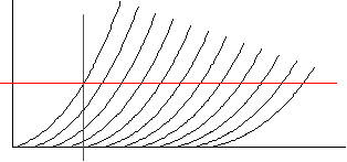
Given the specified output tubes and idle current, 100k makes for a reasonable value. Given 1 mA of current flow through the phase splitter and the 100 volts that develops across this resistor, we are left with 500 volts to divide up for the triode and cathode and plate resistors. Dividing by three is the easiest way to go, but not the best. Since we do not want the triode to experience positive grid voltages, we should give the triode some extra voltage to keep it operating in a negative grid bias range. How much voltage? Graphically, the answer is found by drawing a horizontal line at twice the idle current and marking where this line hits the 0 volts grid line of the tube. This point defines how much additional voltage the tube should have. We then subtract this voltage from the 500 volts and divide by three. The result is then divided by the idle current to yield the cathode and plate resistor values. Mathematically, we multiply the tube's rp by twice the idle current to find the extra voltage needed by the triode:
Vkp = rp2I,
in this example,
125 = 62500 x 2 x 0.001.
The cathode and plate resistor values are
Ra, Rk = (Vb - rp2I) / 3I,
in this example,
125k = (500 - 62500 x 2 x 0.001) / 0.003.
Since rp is not as constant as we would like, the graphical method is more accurate.
|
|
|
|
|