For example, a MOSFET based output stage that used two devices with a transconductance of 1 A/V achieves a 2 A/V input voltage to output current ratio. If used, however, in a lean Class-AB or Class-B amplifier, the output stage's effective transconductance only equals that of a single device (or one bank of output devices).
    Which topology is better? This was a trick question, of course: there is not a better topology without specifying what the intended use is or what restrictions are placed on the circuit.
     For example, if the output devices are pentodes, then the plate referenced variation is preferred, as it provides us a means to driving the top pentode's screen with the an output referenced voltage. This was exemplified in the New York Audio Lab's versions of the Futterman OTL amplifier. Using voltage regulator referenced to the output, these amplifiers fed the output of the regulators to both the top output pentode's screen and to the plate side of the split-load phase splitter. Thus, killing two songbirds with one voltage regulator, if you please. If you pause to think about it, you will realize that a series voltage regulator is nothing more than a voltage shifted follower with the ground as the input source. (In fact, three-pin voltage regulators can be used as output devices in an amplifier. The circuit below shows a single-ended, unity gain, short-circuit protected amplifier made out two LM317s.) 

Split-load, plate-referenced, unity-gain
output stage

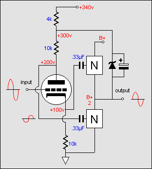
     Thus, any perturbation at the output is directly relayed to the phase splitter's plate resistor. Since the triode's effective rp is hugely increased by the unbypassed cathode resistor, the full magnitude of the perturbation at the output is relayed to the bottom output device unattenuated. This error signal provokes either an increase or a decrease in the current conduction of the bottom output device in an effort to cancel the perturbation.
    In both topologies, the top output device sees a constant ground referenced input signal, which means that the top device will work as hard as the bottom device to keep the output inline with the intended signal. Furthermore, in both topologies, the bottom output device provides no voltage gain, as all potential gain is entirely fed back to its input via its connection to the split-load phase splitter, which results in 100% degeneration and no gain, just as in the case of a cathode follower. So, in other words,
both output devices function as followers. When used in a Class-A amplifier, they effectively equal both devices placed in parallel, which means a doubling the transconductance.

< PREVIOUS

www.tubecad.com   Copyright © 2001 GlassWare   All Rights Reserved

NEXT >

Pg.

2