| John Broskie's Guide to Tube Circuit Analysis & Design |
| June 07 2025 | Post Number 622 |
||||
Crossovers
The least evil crossovers are those that deliver a phase-flat summation from the speaker drivers. Phase-flat crossovers are, paradoxically enough, both common and rare. The simplest and cheapest two-way crossover, the 1st-order, either in parallel or series arrangement, requiring only one capacitor and one inductor, delivers a phase-flat summation. Rare phase-flat crossovers, such as the Baekgaard or Bunkichi-Yamanaka or the Kreskovsky, are so rare that most professional speaker builders have never heard of them. Well, this post reveals my third phase-flat crossover design to add to the list.
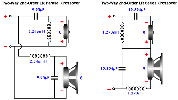
1st-order Crossover
The 1kHz crossover part values are, for both topologies, 19.89µF and 1.273mH. (Of course, if we actually built this crossover, we would use a 20µF capacitor and 1.3mH inductor.) The woofer's and the tweeter's output are down -3dB at the crossover frequency, and the attenuation falls off at -6dB per octave and -20dB per decade of frequencies.
Note that 100Hz is a decade away from 1kHz, and the tweeter's output is down -20dB; also note that from 200Hz down to 100Hz the output is down -6dB. A constant 90 degrees of phase difference exists between both drivers at all frequencies, but the acoustical sum in the air is phase flat, i.e. 0 degrees.
The assumption behind all the graphs I will show is that the woofer and tweeter voicecoils are aligned and that the distance between driver centers is much smaller than the wavelength of the crossover frequency. (Just imagine a high-quality coaxial driver.) Ideally, we should hear neither the tweeter nor the woofer, but only the sum of the two drivers. In other words with the loudspeaker grill cloth in place, we should not be able to guess the number of drivers used. Too many falsely imagine the sound leaving a loudspeaker driver being like a tightly focused beams of light. True, high-frequencies tend to beam, but if you stand behind a loudspeaker, do hear nothing? I once asked a professional loudspeaker driver designer about how to mitigate frequency-modulation distortion, FMD, wherein low-frequency reproduction creates a Doppler-effect distortion upon the high-frequency waves, as the big in-and-out speaker cone motion alternately stretches out the high-frequency tone and compresses it. He told me that it didn't exist; or, rather, he pointed out that it could not be diminished, as the physics of sound transmission always creates FMD. His example was of two identical drivers next to each other, with one producing a 100Hz tone, while its partner produced 1kHz; in the air, the 1kHz tone travels through the same air as does the 100Hz tone, so the 1kHz tone is pulled lower and higher in frequency as it encounters either compressed air or rarefied air created by the 100Hz tone. My counter was that I have heard a great reduction in perceived distortion when using two fullrange drivers with 1st-order crossover at 600Hz. He explained that the reduction I heard was due to vastly smaller cone travel required by the high-frequency fullrange, which kept it within its tiny linear portion of cone excursion. My rebuttal was that he should imagine a huge fullrange electrostatic loudspeaker whose diaphragm covered 20 square feet, but whose excursion, even at 100dB, would be only a fraction of a millimeter. Nonetheless, I believe that he was more right than wrong, as the sound wavelength of 100Hz leaving the driver is independent of the cone size. Returning to the 1st-order crossover, in SPICE simulations, we can see the perfect reproduction of a three-cycle 1kHz tone burst.
Note that sum exactly follows the input signal, but both drivers continue to move beyond the end of the input signal due to the release of stored energy from the capacitor and inductor. Nonetheless, their anti-phase outputs cancel, leaving behind a perfect tone burst. This is the gold standard of loudspeaker performance, which helps to explain both why Vandersteen loudspeakers always use 1st-order crossovers and why they image so well. No smearing.
By the way, another name for phase-flat crossovers is "Transient-Perfect," which by necessity implies both a flat frequency response and a flat phase response. The workaround to the limited tweeter protection offered is to create a three- or four-way loudspeaker, which moves the tweeter's crossover frequency further up the audio spectrum. (In addition, if the crossover points are cascaded (one high-pass filter's output feed another high-pass filter), the tweeter sees a progressively steeper attenuation slope at low-frequencies.)
2nd-Order Crossovers
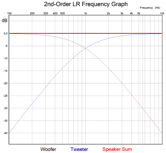
This example's crossover frequency is 1kHz. Both the woofer's and the tweeter's output are down -6dB at the crossover frequency, and the attenuation falls off at -12dB per octave and -40dB per decade of frequencies.
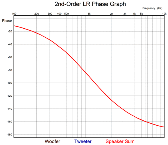
With the Linkwitz-Riley 2nd-order crossover, the tweeter must be wired in anti-phase to the woofer; otherwise, a deep output null appears at the crossover frequency. The phase shift is identical between drivers, so their sum equals that of each driver, with a -90 degree phase shift at the crossover frequency.
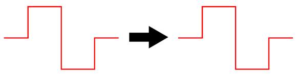
This is not phase flat. You can call it "phase coherent," but it is not phase-flat. Phase-flat music reproduction is important due to how our ears evaluate phase shifts in a musical tone's higher harmonics of its fundamental. In other words, a steady 1kHz pure tone created by a function generator and reproduced through the 1kHz Linkwitz-Riley crossover will sound identical to that from a 1st-order crossover. Few listen, however, to pure steady tones, and musical instruments are replete with their own complex higher harmonic signatures; for example, the same note played on a violin will not sound the same as that tone played through a flute. With the 2nd-order Linkwitz-Riley crossover passing a note played on a musical instrument with a 1kHz fundamental, the note's 4th harmonic shifts by -60 degrees; in contrast, with a phase-flat crossover, zero degrees. Square waves are made up of its fundamental frequency and an infinite series of fundamental frequency's odd harmonics; thus, they readily reveal phase shift.
It is often said to never test a loudspeaker with square waves, as this test will blow out the tweeter. The reason is not hard to find. A square wave at the crossover frequency after passing out of a Linkwitz-Riley 2nd-order crossover will deliver twice the peak voltage to the tweeter, with the woofer seeing only a peak voltage equal to the input voltage. Twice the input signal, four times the instantaneous wattage. It makes sense that phase shifts must enact havoc upon continuous square waves, but they also scramble sinewaves—when the sound wave delivery is not continuous. (Other than a sustained organ note or that from a synthesizer, very little music contains steady tones; instead, we behold an ever shifting, wavering array of notes.) Here is the transient graph for the Linkwitz-Riley 2nd-order crossover, with a tone burst of three cycles at 1kHz:
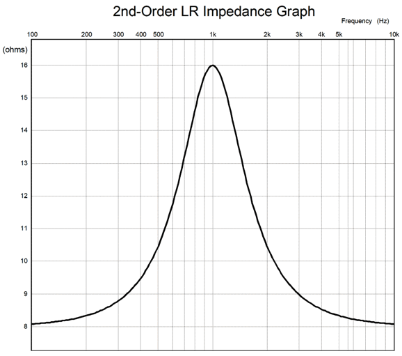
Note that three positive peaks produced, but four negative peaks are also delivered, the first peak in anti-phase to the input signal. In addition, the signal stops at 4 milliseconds, but the summed output continues on for 1ms, smearing the tone burst. So why is the 2nd-order Linkwitz-Riley crossover alignment so popular, for example modern Magnepan loudspeakers use it? First, it was an improvement over the old Butterworth alignment in that yielded a flat frequency response. Second, this crossover uses capacitor values at half the nominal value, but with inductors twice the nominal value; back when ferrite-core crossover inductors were common, high-quality capacitors were the most expensive part of a passive crossover. Today, air-core inductors are just as expensive as film capacitors. The impedance plot is not close to flat:
This doubling of impedance at the crossover frequency makes three-way cascading of filters impossible. In contrast, the Butterworth 2nd-order crossover allows for easy cascading and for the series-cascade topology in multi-driver loudspeaker with several crossover frequencies—something that is only possible with many extra parts and much care with the Linkwitz-Riley alignment. For example, what follows is a four-way series Linkwitz-Riley 2nd-order cascading crossover that uses my signature impedance-flattening networks.
The math is fairly straightforward, but that is a lot of crossover parts. On the other hand, one feature to this four-way crossover topology is that we can use the driver's own internal series inductance (Le) as part of the crossover. For example, if the first crossover is 300Hz and 8-ohm drivers are used throughout, then L1 will be 4.24mH; and if the woofer's Le is 0.64mH, then L1 need only be 3.6mH in value. In other words, no Zobel network is needed for any of the drivers other than, possibly, the tweeter.
3rd-Order Crossovers
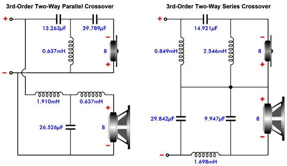
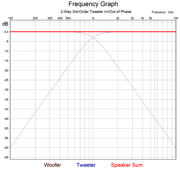
The acoustic sum is frequency flat, as is the impedance plot.
When the tweeter is wired out of phase with the woofer, the phase shift between drivers is a constant 90 degrees. A tone with a fundamental frequency of 1kHz will see its 4th harmonic phase shifted by 60 degrees.
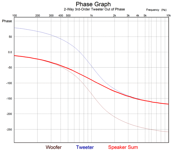
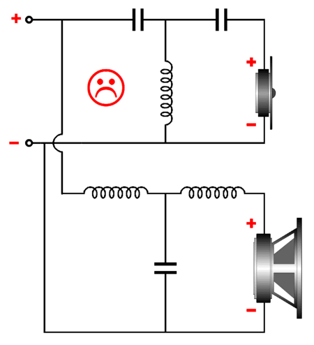
An interesting feature and possible trap of the 3rd-order Butterworth two-way crossover is that the frequency response is the same with the tweeter wired either in phase or with it out of phase to the woofer. That's interesting, but it is also a potential trap. Some loudspeaker designers figure that, since the same flat frequency response results, they might as well wire the both drivers in phase, thereby obtaining some free phase coherence.
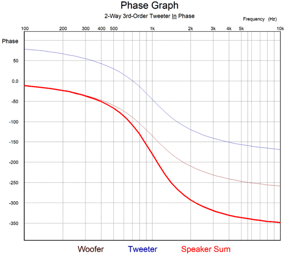
A big mistake. Here's why: with the tweeter wired out of phase, the combined-driver phase goes from 0 degrees at DC to -180 degrees at high-frequencies; with the tweeter wired in phase, 0 degrees at DC to -360 degrees at high-frequencies.
This means that with the tweeter wired in phase with the woofer, the 1kHz tone sees its 4th harmonic phase shifted by 150 degrees! Moreover, as we would expect, the severe phase shift make square-wave reproduction impossible. In addition, it garbles sinewave fidelity with actual music playback, but not laboratory steady harmonic-free sinewaves.
Note that three cycles of 1kHz were delivered, but five positive peaks and five negative peaks show up leaving the crossover. In contrast, with the tweeter wired out of phase relative to the woofer, we get the following results.
Now, we see three positive peaks and four negative peaks show up leaving the crossover. Note that the static frequency response and distortion as measure with steady pure sinewaves in a laboratory are identical with either tweeter phasing, yet our ears can readily hear a difference with actual music playback. In other words, there's no absolute guarantee that what measures the same in a lab is the same in our homes with music playback. A further complication with the 3rd-order crossover is that making a three-way crossover is far more complicated than most imagine. Here is my workaround to the usual headaches associated with a three-way design:
The added resistor and capacitors C3 & C4 along with inductor L5 produce no sound, but they do allow the woofer's output to meld with that of the midrange and tweeter by better aligning their phase relationships. See my Post 539 for more details, but the quick punchline is that the midrange must offer a slightly high SPL to compensate for the resistor's failure to deliver any sound. The genius workaround would be to use a dual-voicecoil midrange (DVC), with one of its voicecoils replacing the resistor. With crossover frequencies of 200Hz and 2kHz, a 6-inch DVC woofer could be used to good effect.
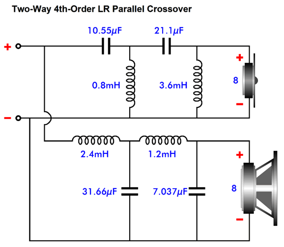
4th-Order Crossovers
Unlike the 2nd-order Linkwitz-Riley crossover, the tweeter must be wired in phase with the woofer. Both drivers are down -6dB at the crossover frequency.
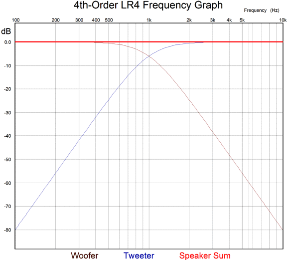
To be -80dB down is to see a voltage reduction of 1/10,000, hence the great tweeter protection. As we might expect, we must pay for this extravagant attenuation with extreme phase shift.
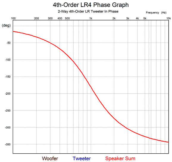
Where the 2nd-order Linkwitz-Riley crossover went from 0 degrees to -180 degrees, the 4th-order Linkwitz-Riley goes from 0 to -360 degrees. (Note that if we flip both the woofer and tweeter phase, there is zero phase shift at the crossover frequency. Alas, this is an imaginary victory, as the total phase shift across the entire bandwidth is still 360 degrees. In additiion, there's no telling if the phase on the recording is in or out of phase.) The transient graph reveals the effect of the phase shift upon the tone burst.
I count five positive peaks and four negative peaks. Given that we should see only three of each, we should expect substantial sonic smearing at the crossover frequency. If we use a 500Hz three-cycle tone burst instead, we get the following result.
Not perfect, but it is certainly better than the tone burst at the crossover frequency of 1kHz. My workaround to the Linkwitz-Riley 4th-order's failings is to add a filler driver, which transforms the crossover radically, so much so that it now delivers a phase-flat output and fairly flat impedance plot.
Note that all the drivers are in phase with each other. Also note that the filler driver's impedance is twice that of the woofer and tweeter; in addition, its SPL is +6dB greater than that of the woofer and tweeter. The filler driver only sees 6dB-per-octave leading and trailing slopes, so it must be capable of exhibiting a wide bandwidth. Fortunately, high-efficiency fullrange drivers are readily available.
The loudspeaker's sum of all three drivers is frequency flat:
Since the both the woofer and tweeter experience a -180 degree phase shift at the crossover frequency, the filler driver—whose output is phase flat at the crossover frequency—must deliver +6dB more SPL at the crossover frequency to undo the inverted signal from the woofer and tweeter. In other words, the filler driver forces a flat phase upon the loudspeaker's output. If we use the three-cycle tone burst to test the crossover for phase-flat output, we should see a clean tone burst.
Note that the filler driver's cone excursions are twice that of the woofer and tweeter. If we remove the three driver's individual outputs, we can better see the resulting tone burst.
The impedance plot is close to flat with resistor-like loudspeaker driver impedances in SPICE simulations:
As 16-ohm driver are so hard to find, we should use 4-ohm woofers and 4-ohm tweeters along with an 8-ohm filler driver to build an actual loudspeaker.
Broskie Phase-Flat 2nd-Order DVC Crossover
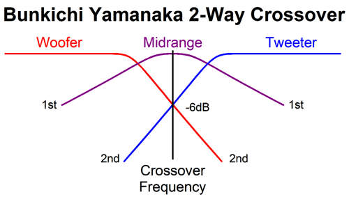
Ever since I first saw in the 1970s the Bunkichi/Yamanaka phase-flat crossover (1967)—that was later used in the Technics SB-7000 three-driver, two-way loudspeaker and, later, in the Bang & Olufsen Uniphase-loudspeaker line—I have been interested in phase-flat crossovers. (See post 475, post 476, post 544, post 564, and post 581 for more information on the Bunkichi/Yamanaka crossover.) This novel phase-flat, two-way crossover used a Linkwitz-Riley 2nd-order crossover with a Q of 0.5 (I believe well before Linkwitz and Riley did, by the way), but with the woofer and tweeter in phase, which resulted in a huge suck-out at the crossover frequency, which was filled in by the "filler" driver (aka, midrange), which had to deliver an SPL 6dB greater than the woofer and tweeter.
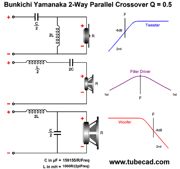
The Yamanaka crossover is easy enough to implement. All that is needed is three drivers, three capacitors, and three inductors.
Sadly, the Yamanaka crossover does not deliver a flat impedance plot across the audio bandwidth, as the impedance dips at the crossover frequency. With a nominal 8-ohm impedance loudspeaker, the Yamanaka falls to 5.33 ohms at the crossover frequency, which means that a nominally 4-ohm loudspeaker would fall to a crushing 2.66 ohms; not good. Moreover, tube power amplifiers much prefer a flat impedance plot.
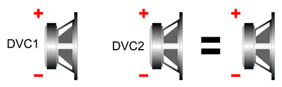
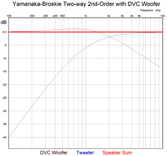
Still, a flat-phase output is a far more worthy goal. I realized that I could replace both the woofer and the filler driver with a single dual-voicecoil woofer, while all the crossover parts would remain the same.
We retain the flat-phase and flat frequency response and the good tweeter protection from the 2nd-order cutoff, but must pay the price of the big dip in the loudspeaker's load impedance. I wanted it all: flat-phase and flat frequency response and flat impedance. This made me remember the 1st-order 3-way series crossover. I saw that I could use the same crossover frequency on both crossover sections, thereby creating a Linkwitz-Riley 2nd-order high-pass filter for the tweeter and bumpy 1st-order slope for the DVC driver.
The math is super simple, as it is the same as that for the 1st-order crossover: C = 159155/R/Fcrv, L = 159.155 x R/Fcrv. (Both of the DVC voicecoils should get its own Zobel network.) The resulting frequency plots look identical to that of the Yamanaka-Broskie 2-way 2nd-order with a DVC woofer.
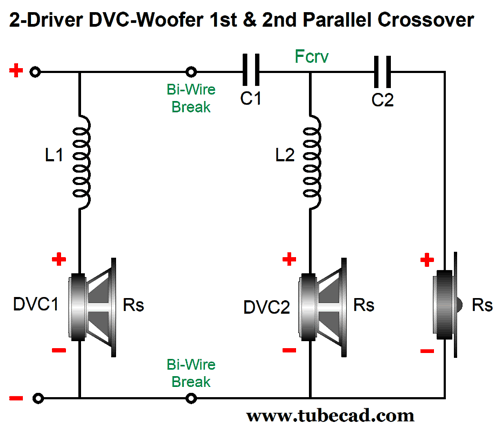
In addition, the impedance plot is as flat as the frequency response and the phase response. Mercy! I got all that I wanted. By the way, the parallel version of this crossover allows for bi-wiring. (See my Post 560 for more details.)
The math is the same as that for the series arrangement: C = 159155/R/Fcrv, L = 159.155 x R/Fcrv. The phase sum is flat.
Some tweeters require more protection than the 2nd-order Linkwitz-Riley high-pass filter provides. I tried to come up with a crossover that held a 3rd-order high-pass filter for the tweeter and a bumpy 1st-order cutoff for the woofer that would sum to phase flat, but it eluded me—until recently that is. I realized that I had come close with a parallel variation on the 2nd-order crossover shown above. It appeared in the same 560 post: 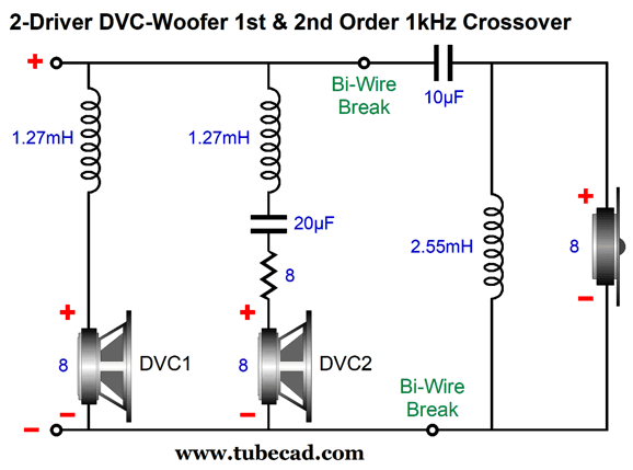 I realized that if we lost the 8-ohm resistor and added an extra capacitor, we might arrive at flat-phase—while giving a 3rd-order high-pass filter to the tweeter, which would offer even more protection to the delicate tweeter.
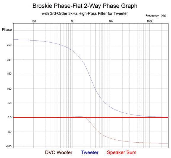
Broskie Phase-Flat 3rd-Order DVC Crossover
The 3rd-order high-pass filter is a conventional 3kHz Butterworth, while the remaining capacitor and inductors are the same values as in 1st-order crossover.
Note that the woofer must deliver greater output at the Crossover frequency than it did in the previous version with a 2nd-order high-pass filter for the tweeter. The transient reponse is excellent:
The tone burst's fidelity is possible due to a flat phase and frequency response.
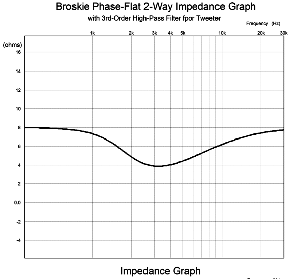
Well, this new crossover topology gets two stars, one for a flat frequency response and one for a flat-phase response. It fails to earn its third star, as it does not present a flat load impedance top the power amplifier.
If the impedance peaked rather than dipped, we could apply an impedance-dipping network. The best workaround I could come up with was to flatten the impedance plot to 4 ohms, since I could not raise it to 8 ohms.
With the added impedance-flattening network the impedance plot looks like this:
I don't much like the wasted power used to heat the 8-ohm resistor. One idea I had was that we put some of that wasted power to use by driving a rear-firing woofer, which would also serve to undo low-frequency diffraction loss.
The resulting impedance plot is within ±1 ohm relative to 4 ohms.
The added woofer's output will be down -3dB at 1590Hz. Much like a recoilless rifle that fires two bullets at one, one forward and one backward, the rear-firing woofer will cancel the front-firing woofer's back-and-forth rocking of the cabinet. Moreover, small loudspeaker cabinets exhibit a diffraction loss at low-frequencies due to the speaker radiating omnidirectionally at low frequencies, but directionally at higher frequencies. The rear-firing woofer would undo the loss of bass. By the way, we could replace the 8-ohm resistor with a tweeter, which would see a 1st-order 10kHz crossover frequency, thereby adding some high-frequency shimmer to the reflected sound. This designs example shows a 3kHz crossover frequency, but one with a crossover frequency closer to 2kHz or, even, 1kHz is more likely. Here is the math required to create my crossover:
Note that driver impedances are fixed in value. Yes, four drivers, two on the front, two on the back. Of course, we could limit ourselves to just two, a DVC woofer and a tweeter. Another possibility is that we use two woofers in place of the DVC driver, probably in a D'Appolito arrangement (aka MTM, for Midrange-Tweeter-Midrange). This would offer a far greater choice of woofers (or mid-woofers); but if the crossover frequency is too high, we cannot expect the two woofer to meld nearly as well as with the DVC equivalent. In fact, I would strive to set the crossover frequency not much higher than 1.5kHz with two woofers in place of the DVC. Other than ribbon, planar, and air-motion-transformers (AMT, aka Heil) loudspeaker drivers, all round-voice-coiled drivers exhibit an internal series inductance (Le). Some high-end woofers hold intricate magnet assemblies that often contain a copper ring that deliver less series inductance, but they, too, do still present some inductance. Well, the DVC's own two voicecoils each exhibit Le, which in this crossover topology can be used as part of the crossover, as inductors L2 and L3 can be reduced in value by the amount of Le the DVC driver presents. In other words, no Zobel networks for the DVC driver, which is a big feature.
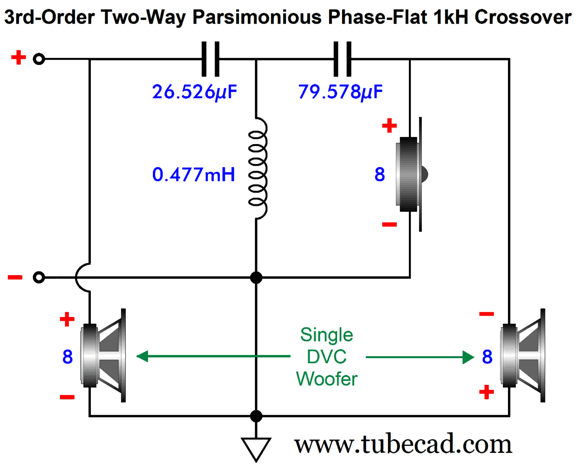
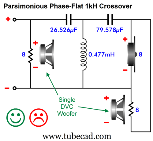
Parsimonious Phase-Flat Crossover
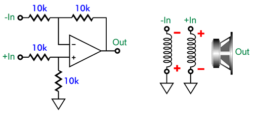
Mencken does not cover what happens when dealing not with a half dozen but hundreds spurts… Exiting self-congratulatory mode, when I look at the DCV driver's two voicecoils, I also see that they are analogous to a differential amplifier circuit.
Apply the same signal to the differential amplifier's two inputs and no signal comes out. Apply the same signal to the DVC driver's two voicecoils and zero cone motion results. For example, imagine attaching a 1.5V battery to both voicecoils, so one voicecoil would push the cone forward, while its brother would pull the cone backward. The net result: nothing. To make this point, here is a hybrid phase-flat crossover that uses a differential amplifier with single-voicecoil woofer.
The amazing, fantastic aspect of this hybrid design is that 3rd-order high-pass filter can be totally botched, wrong part values, poor part types, yet the summed output will be phase flat, frequency flat. How's that possible? The differential amplifier knows what the input signal is and it must deliver at its output the missing portion required to sum to unity. The actual implementation would cascade an OpAmp (powered by only a ±12Vdc power supply) configured as a differential amplifier into power amplifier (powered by only a ±45Vdc power supply).
By the way, this hybrid crossover might prove ideal with a high-efficiency tweeter, such as an 8-ohm horn-loaded design or with a fullrange driver, as small class-D power amplifier could hide within the enclosure, driving the 4-ohm woofer to a phase-flat summation. Moreover, a flea-power tube-based power amplifier can thunder with a 100+ dB horn high-frequency driver, while the class-D power amplifier can bring a 4-ohm, low-efficiency woofer up to the horn's SPL—all while using a relatively small loudspeaker enclosure. Now, let's look at an analogous passive phase-flat crossover.
One voicecoil sees the full audio bandwidth, while its brother voicecoil sees the same signal as the tweeter sees. As far as the 3rd-order high-pass filter is concerned it is driving a 4-ohm tweeter. The summed result is the same as that of the hybrid crossover. The downside is that load impedance presented to the power amplifier is 8 ohms at low frequencies, but 2.66 ohms at high frequencies. Really, 2.66 ohms? Yes, really. I realize that as drawn, this schematic might not make sense. Here is a redrawn:
Perhaps, you can better see that at high frequencies, three 8-ohm resistances are in parallel, 8 || 8 || 8 = 2.666…. Why the sad face? I can only see this design actually working with a truly low crossover frequency, say 200Hz to 500Hz, and with a DVC fullrange driver or with a planar driver, which presents virtually no series inductance, such as the Magnepan or the old Apogee loudspeakers. Here's the thing with differential amplifier circuits: they usually require 0.1% resistors to work well. Nothing about a loudspeaker driver, other than its weight, is 0.1%. Still, for out-of-the-box thinking, I feel that this design is worthy of two gold stars. By the way, class-D amplifiers are quite happy driving 2-ohm loads, so this parsimonious crossover might not be all that bad after all.
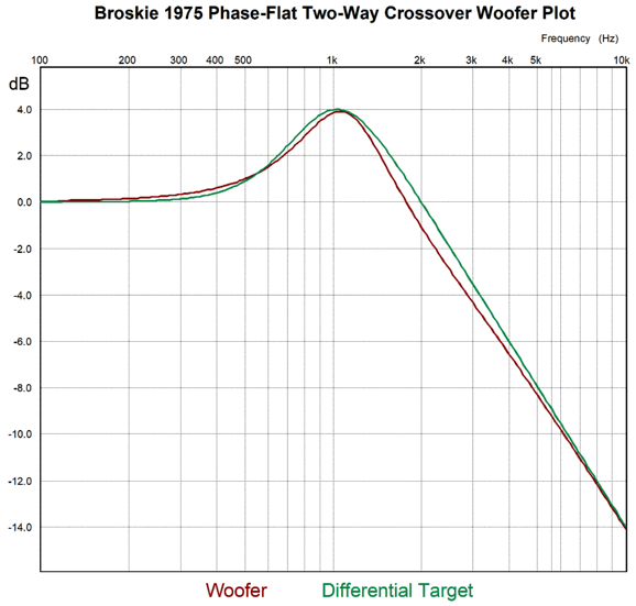
Broskie 1975 Flat-Phase Crossover My test-build speakers held one 5in woofer in a tall, narrow transmission-line cabinet, with an Audex 1in dome tweeter that got its signal from a 3rd-order Butterworth high-pass filter. Sadly, I long ago lost my original schematic. (I do remember making the PCB for the crossover, and that it held 19 parts. Of course, many of the parts were just capacitors and resistors either in parallel or in series.) Here is my attempted resurrection of the topology:
Other than the 3rd-order Butterworth 1kHz high-pass filter and the 0.6365mH inductor, I had to guesstimate the other part values. I have a vague memory of the crossover requiring an insertion loss of 4.2dB, but that amount of attenuation didn't work that well in SPICE simulations. The values here shown result in a loss of -5dB from the woofer. What follows is the woofer's plot next to the desired plot, which was easily created by using a differential amplifier to compare the input signal to the output signal the tweeter sees and deriving the perfect complementary woofer output.
Close, but no cigar or even a used 12AX7. Here is the three-cycle tone burst test:
Unfortunately, I am long past the days when I could burn through the math behind this crossover while eating my breakfast. Having just said that, I realize from a quick inspection of the transient graph that the more likely required insertion loss should be -6dB. Well, a -6dB loss is huge, as it translates into a power reduction of 75%. For example, 100W goes in, but as far as the woofer is concerned, it only gets 25W. (With -6dB of loss, the woofer would be, at low frequencies, in parallel with a resistor of equal resistance to the woofer's impedance, and the woofer would see 1/2 the AC voltage and 1/2 the AC current; thus, one quarter the wattage. In other words, this crossover looks like a non-starter.
Music Recommendation: Elan Mehler's Trouble In Mind
//JRB
Did you enjoy my post? Do you want to see me make it to post 1,000? If so, think about supporting me at Patreon.
User Guides for GlassWare Software
For those of you who still have old computers running Windows XP (32-bit) or any other Windows 32-bit OS, I have setup the download availability of my old old standards: Tube CAD, SE Amp CAD, and Audio Gadgets. The downloads are at the GlassWare-Yahoo store and the price is only $9.95 for each program. So many have asked that I had to do it. WARNING: THESE THREE PROGRAMS WILL NOT RUN UNDER VISTA 64-Bit or WINDOWS 7, 8, and 10 if the OS is not 32-bit or if it is a 64-bit OS. I do plan on remaking all of these programs into 64-bit versions, but it will be a huge ordeal, as programming requires vast chunks of noise-free time, something very rare with children running about. Ideally, I would love to come out with versions that run on iPads and Android-OS tablets.
|
I know that some readers wish to avoid Patreon, so here is a PayPal button instead. Thanks. John Broskie
John Gives
Special Thanks to the Special 92! To all my patrons, all 92 of them, thank you all again. I want to especially thank
I am truly stunned and appreciative of their support. In addition I want to thank the following patrons:
All of your support makes a big difference. I would love to arrive at the point where creating my posts was my top priority of the day, not something that I have to steal time from other obligations to do. The more support I get, the higher up these posts move up in deserving attention.
If you have been reading my posts, you know that my lifetime goal is reaching post number one thousand. I have 378 more to go. My second goal was to gather 1,000 patrons. Well, that no longer seems possible to me, so I will shoot for a mighty 100 instead. Thus, I have just 8 patrons to go. Help me get there. Thanks.
New URL of the GlassWare website |
||||


| www.tubecad.com Copyright © 1999-2025 GlassWare All Rights Reserved |