| John Broskie's Guide to Tube Circuit Analysis & Design |
| April 30 2025 | Post Number 620 |
||||
Single-Ended Cornucopia
Safe, Safer, Safest SE Headphone Amplifier
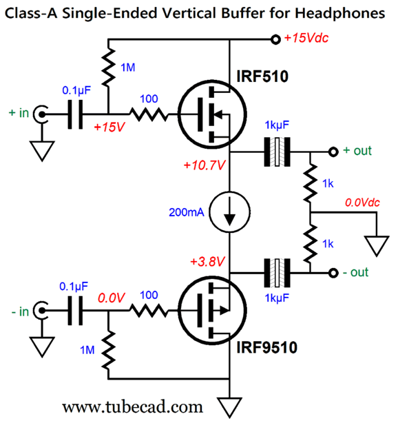
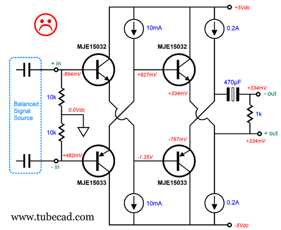
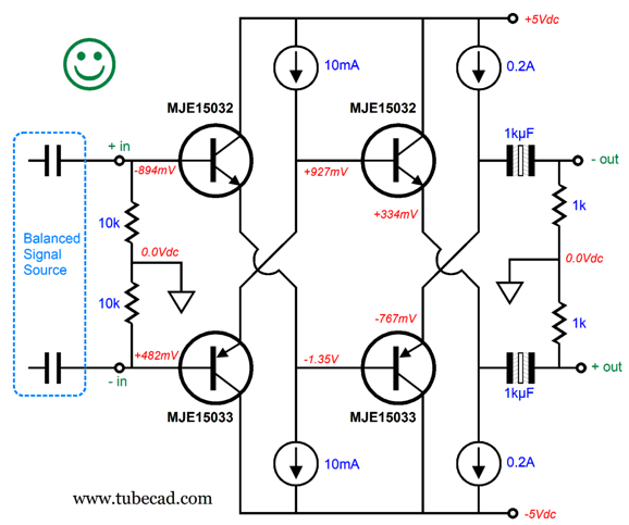
(The assumption behind the original design was that since modern high-end DAC often sport balanced output jack and offer remote controls to adjust the volume, this circuit is all we need to add to be able to drive balanced dynamic headphones.) He pointed out that if we lost the bottom 1kµF output coupling capacitor, the headphone drivers would still see zero differential voltage.
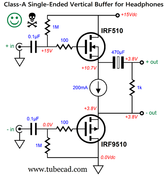
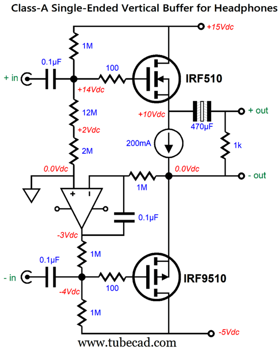
Note that the single output coupling capacitor has halved in value. The logic behind this move is that using the two output coupling capacitors, which are effectively in series, halves their capacitance, unlike resistances which add in series. The required-capacitance formula is easy enough: Capacitor = 159155/Frequency/Resistance where the capacitor's value is in µF; the frequency is the low-end cutoff frequency; and the resistance is the load impedance. With 32-ohm headphones, the 470µF coupling capacitor will produce a low-frequency cutoff of 10.6Hz. With 300-ohm headphones, we could get away with a 30µF to 47µF coupling capacitor. Also note that this is a balanced power buffer that accepts a balanced input signal and delivers a balanced output signal. In other words, the output is not grounded. In fact, at idle there's a 3.8Vdc voltage difference between the two output terminals and ground. Admittedly, 3.8Vdc is not all that much voltage and the male connector prongs enter a female jack and the headphone drivers are sealed within, so there's not much chance of an electrical short. Still, the Underwriter's Laboratory (UL) would not be pleased. Moreover, I cannot imagine a situation wherein a headphone listener would get shocked, but a failure of imagination does not prevent accidents. In short, my recommendation was to use the two output coupling capacitors. Besides, they are small and relatively inexpensive—even the slightly more expensive but better-sounding non-polarized electrolytic capacitors. Well, the more I think about it, I can see a way for him to get away with the single coupling capacitor and still remain safe—or, at least remain safer. One thought that came to mind was that if we could lower DC offset voltage from 3.8V to something closer to 0.38V, the single-capacitor setup would look less scary. Here is what I came up with:
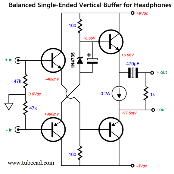
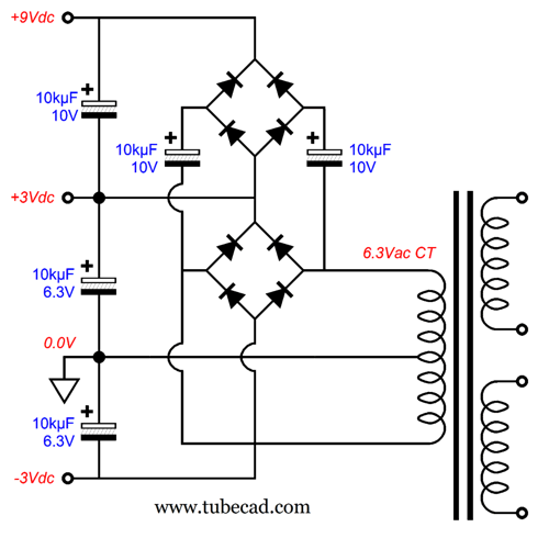
Do not be fooled into thinking that we have a diamond circuit here, as the classic diamond circuit is an unbalanced circuit, not a balanced one. By cascading an NPN transistor into a PNP transistor we get close to a 0.0V DC offset; in this example, the offset is only 97.5 millivolts. If these two transistors attach (closely) to the same heatsink, they will track each other, which results in a fairly-fixed DC output voltage; in other words, changes in ambient temperature do not result in big DC offsets. The 6.2V 1W zener diode creates the voltage shift needed to raise the topmost transistor's base. What makes this design extra odd is the nonsymmetrical bipolar power supply, whose -3Vdc and +9Vdc power-supply rails are anything but common. Nonetheless, making such a power supply is only slightly difficult.
Two bridge rectifiers and five capacitors along with a center-tapped power transformer are all that is needed. Still, a more conventional and congenial power supply is the symmetrical bipolar power supply, which we could use with this design with the addition of a second constant-current source.
Yes, we gained a constant-current source, but we lost a bypassed zener. So, have we arrived? No, sadly, there's one problem with this design, which is that it assumes a balanced signal source that is output-capacitor free; in other words, DC coupled. Such a coupling-capacitor-free DAC will be hard to find, as audio-gear manufacturers, rightly, fear DC offsets, as a DC power amplifier can magnify small DC offsets into woofer-burning big DC offsets.
Note that the DC offset has gown threefold. Why? Transistors draw current from their bases, unlike vacuum tubes that only draw grid current when the grid is positive relative to the cathode, but otherwise operable with negative grids. Bipolar transistors are "enhancement" electronic devices must be turned on by having their bases see a greater voltage than their emitters. Well, even a small current flow through a 10k base resistor will create a sizeable voltage drop. Thus, the safer bet is to use the following design instead.
With the 200mA two constant-current sources, the peak potential output voltage swing into a 32-ohm load will be 6.4Vpk, which is crazy loud, as most headphones play plenty loud with just 1Vpk of voltage swing. On the other hand, some planar headphones are shockingly low-efficient. In fact, we might need 8Vpk of output, which we can achieve by increasing the constant-current sources to 0.25A. It looks like the move to bipolar transistors from MOSFETs didn't pan out. I decided to return to the original MOSFET-based design and add bipolar power supply and a DC servo.
Only one output coupling capacitor. The DC servo eliminates any DC offset, and it's OpAmp can run off the asymmetrical bipolar power supply. The 200mA constant-current source can be made from an LM317 and a 6.2-ohm resistor. The asymmetrical bipolar power supply will require an 8Vac center-tapped primary. All in all, this is probably the best way to forgo the second output coupling capacitor. If we move away from the DAC's balanced output to an active balanced line-stage amplifier's output, we could build a balanced single-ended power amplifier based on this topology.
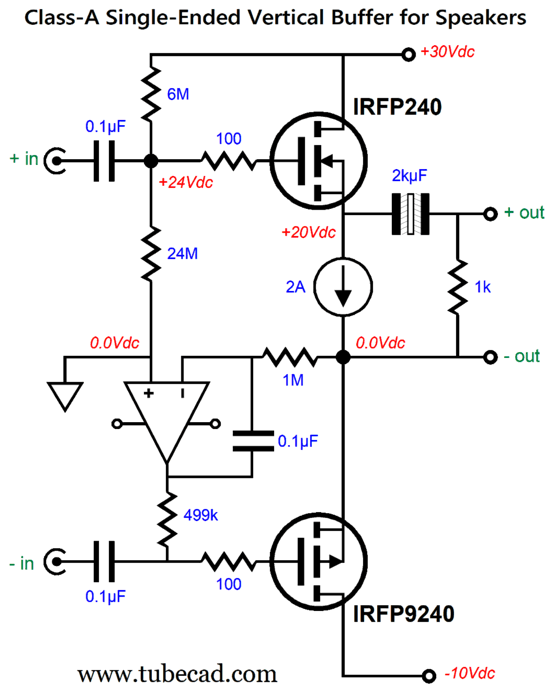
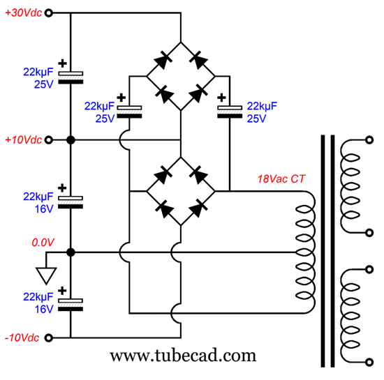
The 2A constant-current source limits the peak voltage output swing to 16Vpk, which into an 8-ohm loudspeaker equals 16W, as power = Voltage²/2R and 16²/16 = 16. The power supply looks like this:
I would use a 300VA toroidal power transformer. Note that the power-supply capacitors need only be rated for 16V and 25V. In addition, I would use a tube-based balanced line-stage amplifier. If we wanted to drive 4-ohm loudspeakers, then we would have to increase the constant-current source to 2.8A and reduce the bipolar power supply rail voltages to +22Vdc and -7Vdc. Or, we could up the idle current to 4A, which would deliver 32W into 4 ohms, but would double the dissipation of the MOSFETs and constant-current source. Sticking to the 2A constant-current source and an 8-ohm load, the total dissipation is 80W, which makes the efficiency only 20%, as 16W/80W = 0.2. Considering that the theoretical maximum efficiency for a constant-current-source-loaded single-ended amplifier is 25%, the 20% is not too severe. No one ever said that class-A operation was for sissies. In contrast, an inductor-loaded single-ended amplifier boasts a theoretical maximum efficiency of 50%.
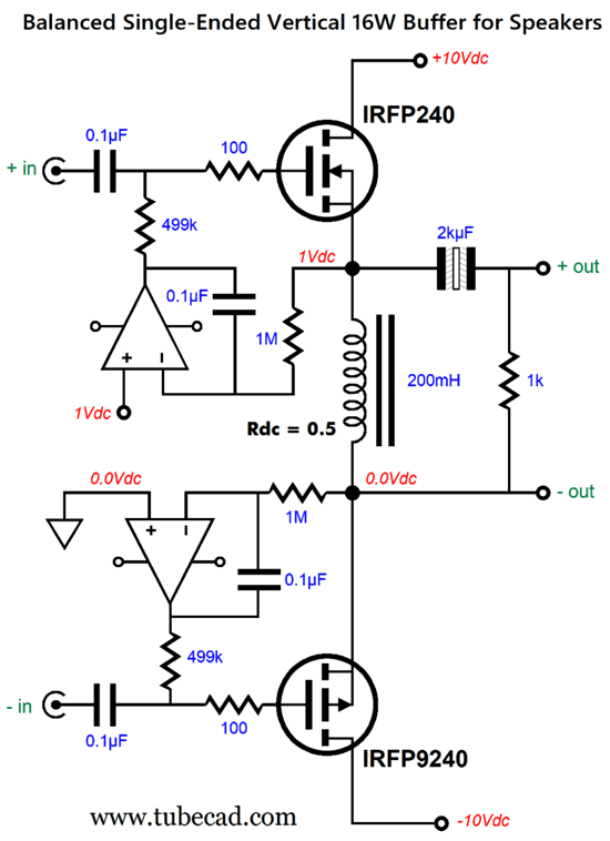
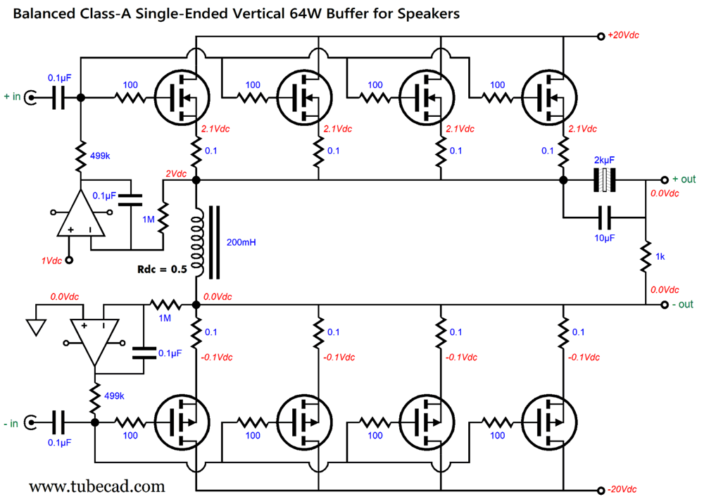
Note the symmetrical bipolar power supply of ±10Vdc. The inductor replaced the constant-current source. Since the inductor is made from iron and wire, the inductor exhibits a DC resistance, which we can use in auto-biasing the power buffer. The top OpAmp monitors the DC voltage drop across the inductor, ensuring a DC voltage drop of 1Vdc. Mind you, the inductor's DC resistance will vary with heat, with the resistance increasing with temperature. In other words, at startup, the power buffer's idle current will exceed 2A, until the inductor's winding heats up and the idle current falls to 2A. What if we want even more output power?
The idle current of 4A against the total of 40V of power-supply voltage develops a dissipation of 160W, for which we could get 64W of single-ended glory. Put redundantly, 64W of single-ended class-A glory.
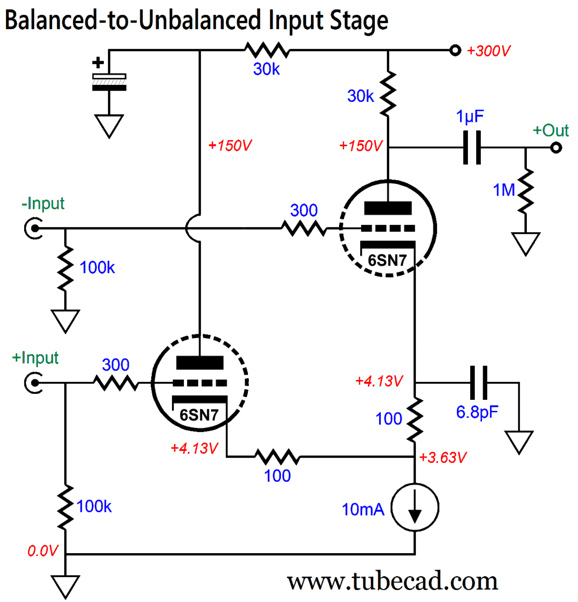
Balanced-to-Unbalanced Input Stage
The unbalancing circuits in post 619 were mostly hybrid, transistor-tube circuits, which is not to everyone's taste. There were a few pure-tube versions (with the exception of the solid-state constant-current source), such as the following circuit.
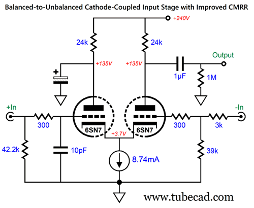
The 10pF capacitor and 3k resistor were added to the textbook Cathode-Coupled amplifier topology to increase the CMRR. The underlining assumption behind this modification was that the balanced signal source presented a low output impedance. This may not prove to be the case, however, especially with tube-based line-stage amplifiers (i.e. preamps). For example, if the output impedance is just 300 ohms, the 10pF capacitor must be replaced with a 5pF capacitor; the 3k resistor, with a 2.7k resistor. After some head scratching, I found a solution in my moving the CMRR-enhancing parts to the cathode side of the circuit.
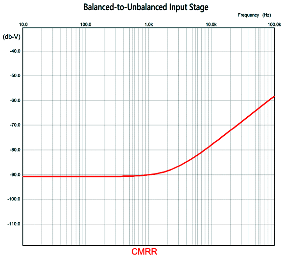
With this variation, the balanced signal source's output impedance does not matter as much. The left triode functions as a cathode follower that drives the right triode's cathode through the two 100-ohm resistors. The 6.8pF capacitor balances the high-frequency responses between the two phases of signal. Here is the resulting CMRR.
That’s pretty darn impressive. By the way, without the added 6.8pF capacitor, the CMRR at 100kHz worsens by 30dB. With a ±1Vpk balanced input signal, the gain comes in at 27.1dB. The high-frequency -3dB cutoff frequency is over 2MHz. Great performance, but I worried about the constant-current source getting too low an overhead voltage when encountering ±2.2Vpk balanced input signals. I needn't have worried, as the constant-current source still experiences a 2.4V voltage drop with this hot input signal. (The LM334 constant-current source IC needs at least 1.5V of voltage drop with 10mA of current flow.) Of course, if the constant-current source terminated into a negative bipolar power supply rail, instead of ground, this would not be a concern. By the way, with a ±2.2Vpk balanced input signal, the output voltage swing is 54.3Vpk.
Single-Ended Super-Triode
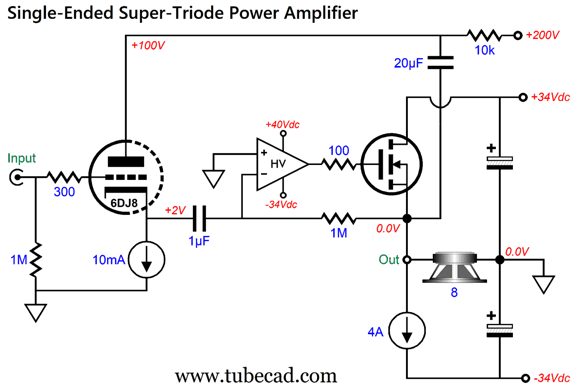
The following design uses a high-voltage OpAmp both to drive the MOSFET and act as a DC servo to eliminate an offset voltage at the output.
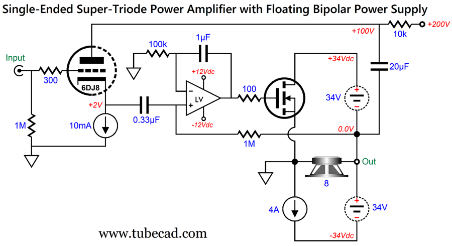
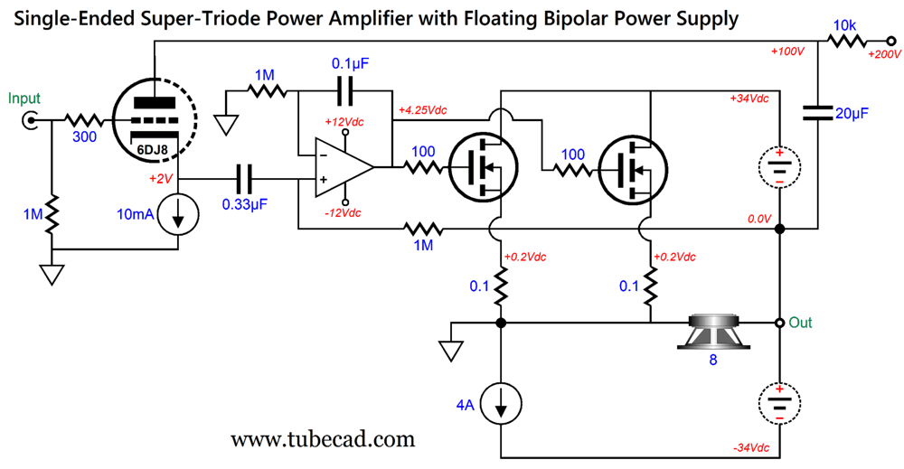
Although the 4A constant-current source sets the idle current flow, the 6DJ8 is in charge of the MOSFET's AC current conduction. This is what makes the super-triode magic take hold. Note that the high-voltage OpAmp's positive power-supply pin attaches to, not the +34Vdc power-supply rail, but +40Vdc that could be derived from the 200Vdc power-supply rail. Why? It needs the higher positive voltage as it must drive the MOSFET's gate about 5V higher than its source voltage. The 4A idle current implies a peak output voltage swing into an 8-ohm load of 32Vpk, which further implies a power output of 64W. Given that the output stage must dissipate 68V against 4A, it must dissipate 272W at idle, putting the output stage's efficiency at 23.5%, which is dang close to the theoretical maximum of 25%. This circuit performed flawlessly in SPICE simulations, but then I used the Ideal-OpAmp SPICE model. Real high-voltage OpAmps are fairly rare and none is perfect. In contrast, normal, low-voltage OpAmps are plentiful and many are excellent. How do we use a low-voltage OpAmp in place of the high-voltage OpAmp? Answer: we flip the OpAmp's inputs and ground the MOSFET's source and a add floating power supply.
The OpAmp no longer inverts the 6DJ8's cathode signal, but the MOSFET now does invert the output signal. In other words, the super-triode function remains intact, as the triode still controls the output. The OpAmp now runs off ±12Vdc rails and still maintains a DC-free output. The dashed lines denote a floating power supply, i.e. one that is not grounded. Conceptually, it is often easier to just imagine two 34-volt batteries in series, as many assume that the power supply creates the "ground." Ground is simply the signal's reference point. In this circuit, the 200V power supply will be grounded. Now, 4A against 34 volts produces 136W of heat dissipation from the MOSFET (and also 136W the from the constant-current source, making for a total of 272W per channel). Of course, that is a crazy amount of heat for any single MOSFET. The workaround is to place many MOSFETs in parallel.
Although the schematic holds two MOSFETs, a more likely number of output MOSFETs is closer to four, if not six or eight. With eight MOSFETs, each MOSFET dissipates only 17W, which is a comfortable amount of heat. Another approach is to place the extra MOSFETs vertically; the cascode arrangement being an obvious example.
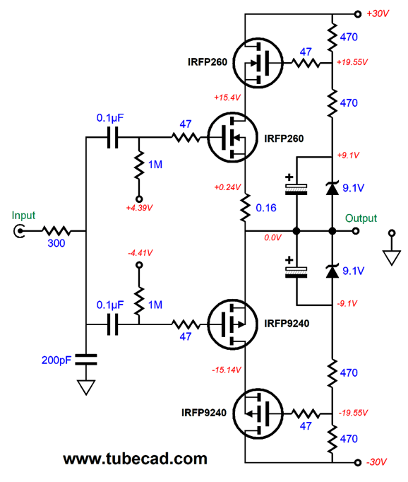
(Yes, this is a push-pull example, so just ignore the top IRFP9240 and imagine a constant-current source in its place.) The advantage to the cascode is that the MOSFET's input capacitance is greatly reduced compared to the parallel arrangement. The downside is the added complexity and slightly less potential output power, as each MOSFET requires some voltage overhead (i.e. source-to-drain voltage) to pass high current. In addition, the cascode arrangement will dissipate just as much heat at idle as the parallel arrangement. In contrast, the class-G arrangement can reduce the dissipation to a third.
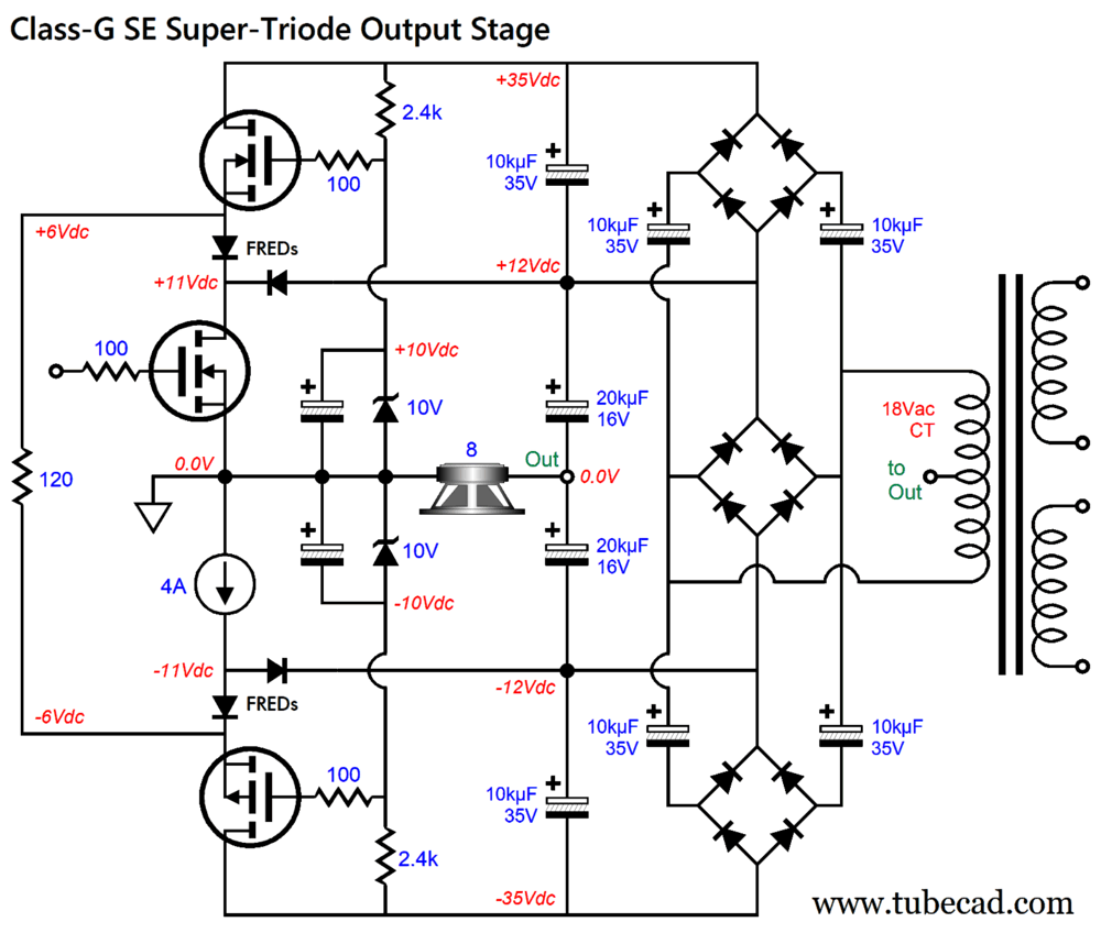
This bipolar power supply is stall floating, as it makes no direct connection to ground. The 120-ohm resistor is my own secret-sauce contribution to class-G operation, as it prevents oscillations at the transitions in current conduction when the top or bottom MOSFETs suddenly turn on or turn off. With my added resistor, they never turn off. At idle, the total dissipation per channel is only 103W (do not forget the heat from the 120-ohm resistor and the top and bottom MOSFETs), only 38% of the non-class-G arrangement's dissipation. The amazing thing is that this class-G arrangement works just as well as the more conventional setup that uses a grounded bipolar power supply. This shows the power of symmetry. Okay, how about losing the 4A constant-current source and replacing it with an inductor?
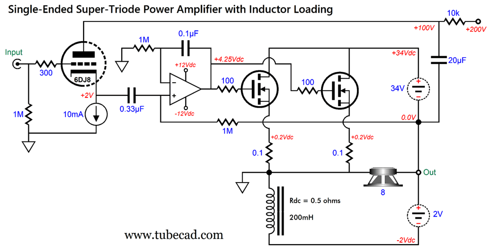
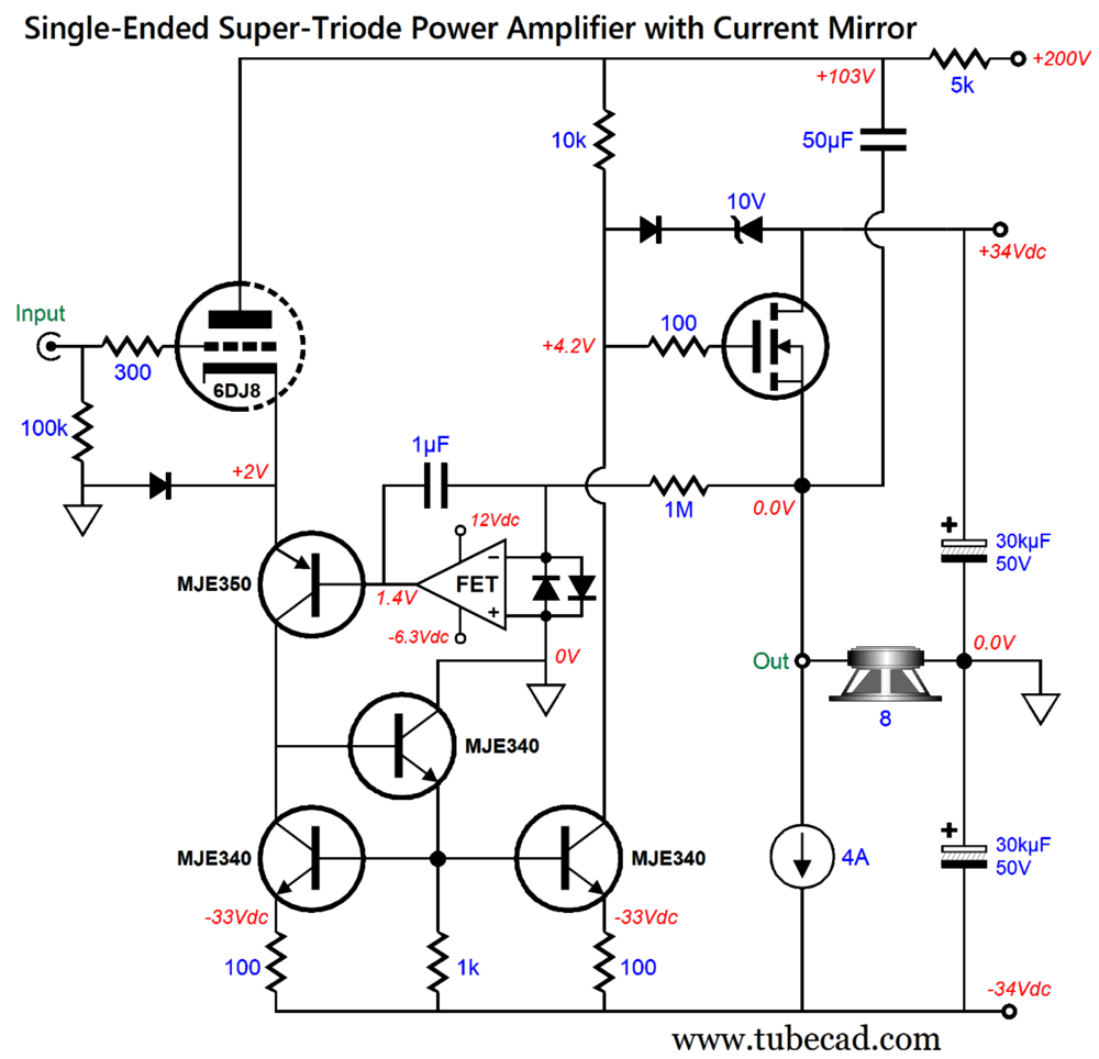
An ideal inductor, like the ideal capacitor, dissipates zero heat. Real inductors are made from iron and copper wire. Perhaps one day we will have inductors made from super-conducting windings, but until that day we are stuck with a big inductor that exhibits a DC resistance. Well, why not exploit this seeming liability? The OpAmp prevents a DC offset voltage at the output, which means it also effectively forces a 2V voltage drop across the inductor's 0.5-ohm DC resistance, which implies a 4A idle current. Of course, the inductor will dissipate some heat, 8W, and its DC resistance will increase with heat. In other words, its DCR might be only 0.4 ohms when cold, but once heated will exhibit the desired 0.5 ohms. This means that at turn on the idle current will peak at 5A, but level off to 3A as the inductor heats up. What about applying the class-G arrangement to the MOSFET side of the output stage? We could, but I am too lazy to draw the schematic, so I will leave to the reader's imagination. Are we done? I know that some do not deem any audio gear containing an OpAmp truly high-end, so what if we lose the OpAmp, replacing it with some discrete bipolar transistors? What I came up with was using a current mirror to let the triode indirectly drive the MOSFET's gate. Wouldn't this violate my first rule of super-triode operation, i.e. the triode must run under constant current? Yes, it does, but only by a little, as I threw in some bootstrapping, so the triode's current flow variation is tiny.
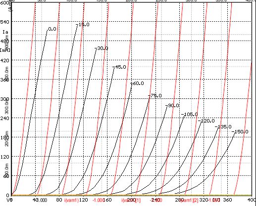
The MJE350 PNP transistor's emitter presents a truly low-impedance to the triode's cathode. The OpAmp's only job is to act as a DC servo that eliminates a DC offset at the output. The diode is needed to prevent the output from slamming to the positive power-supply rail voltage at startup, when the triode is cold and still not conducting. The three MJE340 NPN transistors form a fancy current mirror that relays the triode's current conduction to the 10k collector resistor, which creates an inverted signal to drive the MOSFET's gate. Note well where the 10k resistor terminates, it's not the 200V power-supply rail. Effectively, it's terminated in the amplifier's output via the 50µF capacitor. In other words, bootstrapping. The triode only needs to vary its current conduction by the idle current divided by the MOSFET's transconductance and further divided by 10k. For example, let's assume a transconductance of 10A/1V for the MOSFET, so we have 4/10/10000 or 0.04mA. With the 6DJ8's idle current flow of 10mA, this represents a 0.4% change in current flow. Why don't we replace the 10k resistor with high-voltage constant-current source? We could, but in SPICE simulations the resistor delivers better performance, amazingly enough. I haven't showed any the SPICE-generated Fourier graphs. Why not? They all displayed unbelievably good plotlines (i.e. ultra-low distortion), which we would expect from the SPICE triode models portraying a perfectly constant amplification factor (mu); reality differs. Here SPICE-generated plate curves (red) are overlaid upon the 6C33's actual curves derived from a curve tracer, which I found at the Audiomatica website.
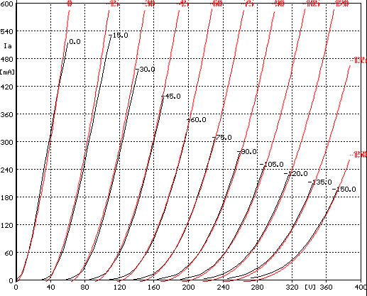
Note the perfectly spaced plotlines from the SPICE model versus the real plate curves. Do not forget that the whole point to the Super-Triode approach is that we want the triode's transfer function, warts and all, to be superimposed upon the amplifier's output. You might be wondering how my own True Curves math model of the 6C33 compares to the curve tracer-generated plot lines. Here is the answer.
Not too shabby.
Music Recommendation: Prestomusic Beyond the tastefully truncated catalog (do you really want to be offered a "Chopin for Cat Lovers" or a "Classical Music for Slackers" album?), Prestomusic offers many high-res albums and downloadable PDFs of the album's booklet, which I deem a huge feature. (I sorely miss the LP's back covers and inner folds, as they allowed for many a wonderful capsule essay on the album's contents, whereas the CD's booklet failed at hand-feel and size. At least on my computer monitor I can increase the font size.)
The best question to ask is does Prestomusic offer any more or any higher resolution versions of albums than Amazon Music, whose catalog, behooving its Amazon parentage, is simply staggeringly huge? I have found some examples. Prestomusic offers all five of their United Strings of Europe albums in 24-bit, 192kHz, whereas Amazon Music offers the same five albums, but only one is 100% unalloyed 24-bit, 192kHz, the others hold a mix of 24-bit, 192kHz and CD resolution tracks. (Amazon Music seems to offer 14 albums by this ensemble, but Amazon seems to not understand the distinction between an album and a single.) Another feature is that Prestomusic claims to return more money to the actual music creators than the competing music streamers, with payments based on per second rather than per track. "Claims" was added due to there being some dispute over whether in practice this extra fair outlay is true. I hope it is. I wish that all music-streaming services offered a tip jar with every artist, so I could send directly a cash tip to the artist, which would be added to my monthly bill.
Taylor doesn't need the added cash, but many, if not most, musicians could use and deserve the money. Just yesterday, I gave the young man who made my sandwich a few dollars tip, which would have required a few thousand music streams to equal. The only constant in the music business is that the artist gets screwed. When I have gone to concerts that also offered the sale of CDs, I often bought the CDs in spite of already owning them. Why? I knew that unlike my first purchase of the CDs, this purchase netted the musician ten times more profit; besides, they made good gifts.
The Prestomusic app looks good, but fails to play 24-bit, 192kHz resolution tracks without hiccupping, which is super annoying to hear. (Well, 24-bit, 96kHz plays fine.) Perhaps, this only happens at my house, but with my fiber optic DSL that delivers a download speeds of 1 Gbps I doubt it. In addition, the app fails to offer any casting feature. (By the way, Prestomusic sells their own streamer, but that does little good for the rest of us who already own a streamer.) Moreover, its sound-control options are embarrassingly meager, nor can you download the album for offline listening, a feature offered by all the other streaming services. Weirdly, when I stream from the Prestomusic website app on the Firebird browser, 24-bit, 192kHz resolution tracks play flawlessly; perhaps, the web browser allocates more buffer memory for streaming than the app does. (I have yet to try the Chrome browser, but it might offer casting natively.) My prediction is that in a few years, the Prestomusic catalog will expand and the app will improve. A curated catalog of over 200,000 premium albums, many in high-res, for only $10.99 a month is a deal. Prestomusic offers a one-month-free trial, so it a try.
//JRB
Did you enjoy my post? Do you want to see me make it to post 1,000? If so, think about supporting me at Patreon.
User Guides for GlassWare Software
For those of you who still have old computers running Windows XP (32-bit) or any other Windows 32-bit OS, I have setup the download availability of my old old standards: Tube CAD, SE Amp CAD, and Audio Gadgets. The downloads are at the GlassWare-Yahoo store and the price is only $9.95 for each program. So many have asked that I had to do it. WARNING: THESE THREE PROGRAMS WILL NOT RUN UNDER VISTA 64-Bit or WINDOWS 7, 8, and 10 if the OS is not 32-bit or if it is a 64-bit OS. I do plan on remaking all of these programs into 64-bit versions, but it will be a huge ordeal, as programming requires vast chunks of noise-free time, something very rare with children running about. Ideally, I would love to come out with versions that run on iPads and Android-OS tablets.
|
I know that some readers wish to avoid Patreon, so here is a PayPal button instead. Thanks. John Broskie
John Gives
Special Thanks to the Special 89 To all my patrons, all 89 of them, thank you all again. I want to especially thank
I am truly stunned and appreciative of their support. In addition I want to thank the following patrons:
All of your support makes a big difference. I would love to arrive at the point where creating my posts was my top priority of the day, not something that I have to steal time from other obligations to do. The more support I get, the higher up these posts move up in deserving attention.
If you have been reading my posts, you know that my lifetime goal is reaching post number one thousand. I have 380 more to go. My second goal was to gather 1,000 patrons. Well, that no longer seems possible to me, so I will shoot for a mighty 100 instead. Thus, I have just 11 patrons to go. Help me get there. Thanks.
New URL of the GlassWare website |
||||


| www.tubecad.com Copyright © 1999-2025 GlassWare All Rights Reserved |