| John Broskie's Guide to Tube Circuit Analysis & Design |
19 July 2021 Post Number 540
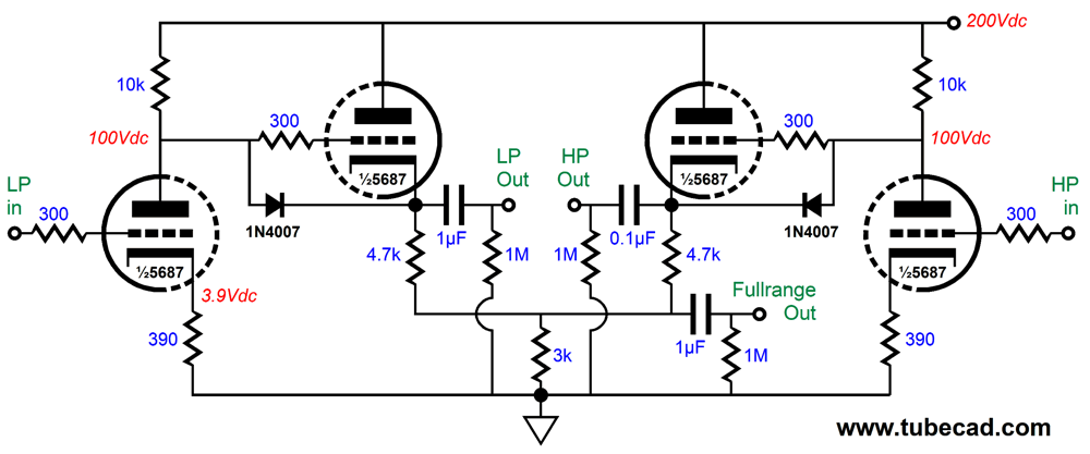
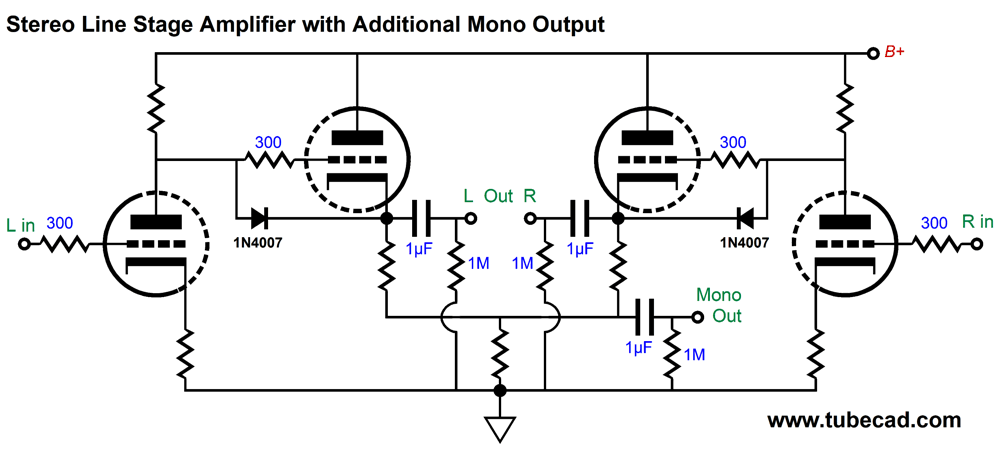
Phono Preamp with RIAA EQ Tone Control Originally, the active crossover was a 2nd-order type, but I wasn't pleased with the stereo imaging, so I swapped the active crossover for a passive 1st-order crossover between amplifiers. Since the amplifiers only put out 20W, I wasn't that worried about blowing the fullrange driver—and even if I did, they were cheap.
The above passive crossover worked well, in spite of a small signal insertion loss of -4dB. Each channel held one Alps 20k audio-taper stereo potentiometer, the bigger dark gray type, not the smaller blue versions. Yes, that meant that I had to adjust two knobs, not one, for volume changes. It was not the torture that many bemoan, as the pots held detents that made matching volumes easy. In addition, I could alter the balance easily. The line-stage amplifier was also very simple, but excellent sounding, as the 5687 is a fine tube. (I had the reputation for having a lead-foot, as I ran much higher idle currents than my friends. Where a buddy might run the 5687 with 1mA of idle current, I ran 10mA. Guess which sounded far better. Of course, I had to pay in decreased tube life and in having to build a more robust power supply, but I deemed the results well worth the exchange.)
This is not a stereo line amplifier, as two of these circuits are needed, one per channel. Note the additional fullrange output at the bottom, which allowed me to use subwoofers later. By the way, we can build the same line-stage for normal non-bi-amped use.
The resulting sound was excellent, but I wondered if I couldn't reduce the part count by incorporating the two crossover filters inside the power amplifiers. My idea was that I could build the 500Hz low-pass filter in the woofer amplifiers and the high-pass filter in the highs amplifiers. The results were not good, as I ran into stability problems with the low-frequency power amplifiers. So, I went back to the external passive crossover in front of the power amplifiers.
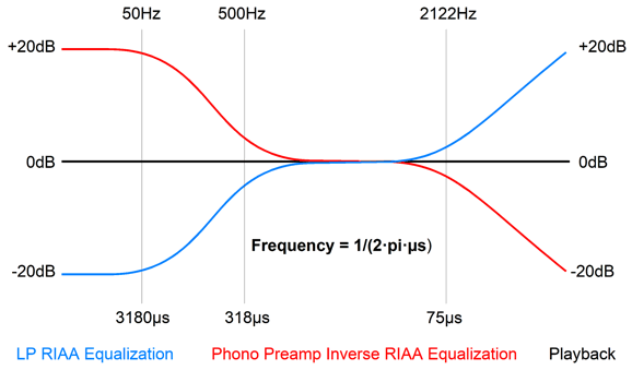
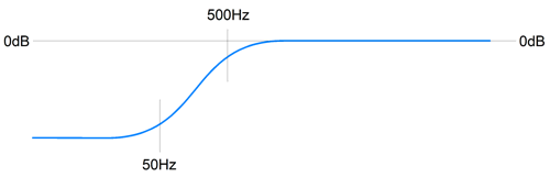
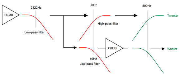
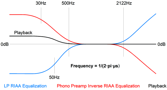
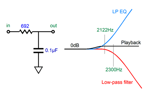
A month or two later, as I examined the RIAA equalization curve that is impressed on an LP record, I noticed that if we imposed the 2122Hz low-pass filter on the non-equalized phono signal, the resulting frequency plotline would come close to being a 500Hz high-pass filter; but not quite, as the high-pass slope flattened below 50Hz.
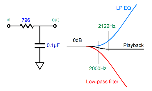
What was needed was a high-pass filter at 50Hz to continue the 500Hz slope down to DC. I then realized that a 50Hz and 2122Hz low-pass filters applied to the phono signal would create a perfect 500Hz 1st-order low-pass crossover. In other words, by exploiting the preexisting equalization on the LP, I could create a two-way 500Hz active crossover.
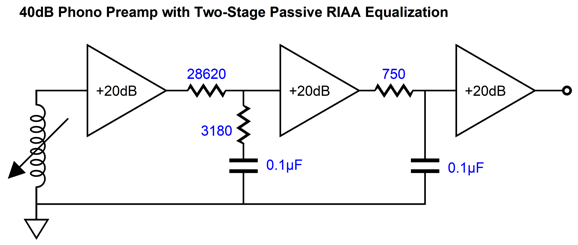
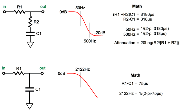
My first attempt was with OpAmps, which I later replaced with a tube-based circuit. Both worked well. Of course, as soon as I built, or bought, more conventional loudspeakers, the active crossover was no longer needed. Years later, I saw that we could alter a phono stage's RIAA equalization to achieve tone control. But my vision was only conceptual, as I never built a test circuit or even evaluated SPICE simulations. Well, that changed recently; I ran many simulations and the results were exactly as I expected, which does not always happen, sadly. The best and, possibly, only way to implement this idea is to use passive RIAA equalization and break the curves into two sections, the first encompassing the 3180µs and 318µs time constants, i.e. the 50Hz and 500Hz shelving frequencies; the second, the 75µs time constant, i.e. the 2122Hz low-pass filter.
Add the three gains together and subtract the insertion loss due to the shelving network of -20dB and we get 40dB. The required math is simple in the extreme compared to the feedback RIAA equalization alternative.
By the way, several readers have bemoaned the excessive and near-universal use of microfarads, i.e. the exclusive use of µF for all capacitor values. For example, they argue that we specify a 10kµF capacitor, we should state 10mF; not 0.1µF, but 100nF, not 0.00033µF, but 330pF. Only capacitor values between 1µF to 999µF should be denoted by µFs. Surely, we can all see their point, but the practice of indicating capacitor values in µF is old and useful. That last word, "useful," is key.
When dealing with time constants in µs, µF make more sense. A time constant of 1µs means that we divide 1 second by 1 million (or multiply by 0.000001), so when we multiply a 1k resistor against a 0.001µF capacitor we are actually multiplying 1000 against 0.000000001F of capacitance and which we then must multiply by one million, which yields a time constant of 1µs. In other words, microfarads already contain the multiply by one million for us. For example, we need a 75µs time constant to impose the 2122Hz low-pass filter of the RIAA equalization curve, so we need only use the following formulas to find the right resistor to go with our 0.01µF capacitor.
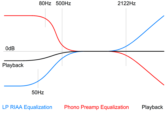
where the capacitor, C, is in µF. We use the middle formula and divide the time constant 75µs by the 0.01µF capacitor value and get 75/0.01 = 7500 ohms; with a 0.33µF capacitor, we get 75/0.33 = 227.273. In other words, using only µF capacitor values makes for easier and quicker math. Had we specified the 0.33µF capacitor as a 330nF capacitor, doing the math would no longer be easy or quick, as we would have to remember to divide by 1000 at the end. We return to RIAA equalization; these two networks combine to impose the inverse RIAA equalization on the preamp's output. If we break the math, shifting the time constants, the output will no longer be flat, which is something that we can exploit. For example, if the shelving network departs from the standard and required 50Hz and 500Hz contour, starting at 30Hz instead of 50Hz, but still ending at 500Hz, we get a bass boost.
The way it works is that the inverse boost starts too early, so we get a boost of the flat signal below 50Hz. (Of course, the transition is slow and smooth.) Conversely, if the shelving network departs from the standard 50Hz and 500Hz contour by beginning at 80Hz, but still ending at 500Hz, we get a bass cut, as the inverse boost starts too late.
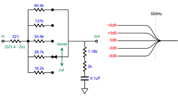
Nice. But how do we retain the ending 500Hz frequency while shifting the start frequency? We leave parts, R2 and C1, unchanged in the shelving network, but alter R1's resistance.
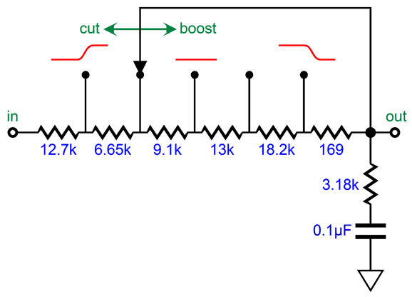
At the middle position, the frequency plotline is flat, as the 3180µs and 318µs time constants are realized. As we rotate the knob to the left, the time constant decreases, so the first transition frequency rises, causing a bass cut. Rotate to the right, the constant increases, so the bass gets a boost. Some solder-slingers have a fear of rotary switches, preferring potentiometers.
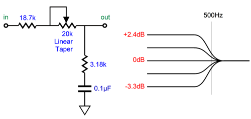
With the potentiometer centered, the pot represents a 10k resistance, which added to the 18.7k resistor value combines to 28.7k, which is dang close to the required 28.62k. How close? Within 1%. (One externality that should be considered is the output impedance of the amplifier driving the shelving network, as this resistance must be included in our calculations.) I fear potentiometer failure, so I much prefer rotary switches. Do not rotary switches fail? They do, but with an open structure, we can apply contact cleaner and we are good to go again; something that is impossible with a sealed potentiometer. In addition, I prefer a parallel arrangement over a series arrangement: fewer solder joints and fewer resistors in the signal path, but slightly more difficult math.
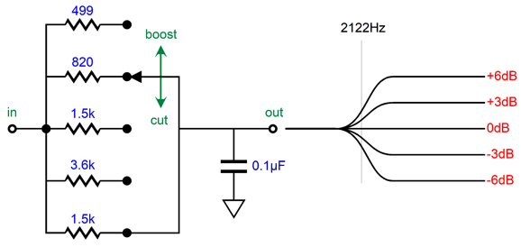
The 221-ohm resistor is required to establish ruler-flat output in the center position. The required 3.18k resistance is made up by the 1.18k and 2k resistors in series. When placing to resistors in series to reach some desired resistor value not made, always strive to use two values close to each other, as was done in this example; otherwise the resistor tolerance will work against us. In other words, we have four possible relations between the two resistors: both resistors are exactly on the money, both are over their stated value, both are under, one is over and one is under. The first and the last possibilities are best, but the last only works if the values are close. For example, say we want exactly 4k of resistance. We place two 1% 2k resistors in series. If both are exactly 2k, great; also great is if one is 1% too high and the other is 1% too low, as 2020 + 1980 = 4000. But if we used 3.9k and 100-ohm resistors, the high-low pairing does not work as well as 3939 + 99 = 4038 ohms; or with the relation flipped, 3861 + 101 = 3962 ohms. If you are making audio gear for a living, it is easy to buy a hundred of both 1% 1.18k and 2k resistors and then make three piles of each value: too low, just right, too high; then pair the too low with the too high and the just-rights 2k resistors with the just-right 1.18k resistors. (Actually, I just realized that 1% 1.6k and 1.58k would have been the better pairing.) In addition, We should subtract the proceeding amplifier output impedance from its value; for example, a Zo of 100 ohms reduces the resistor value to 121 ohms. A five-position rotary switch is shown, but a six-position or eleven-position switch could be used instead—just add more resistors. With a six-position switch, I would give the bass-boost side the extra step, making the progression go from -6dB to -3dB, 0dB, +2db, +4dB, to +6dB. At the other end of the audio spectrum, the LP's frequencies above 2122Hz get boosted 6dB per octave or 20dB per decade, a rising first-order slope in other words. Thus, the inverse RIAA equalization must impose a countervailing low-pass filter at 2122Hz.
If the low-pass filter is tuned to a frequency higher than 2122Hz, we get a highs boost.
Conversely, if the low-pass filter is tuned to a frequency lower than 2122Hz, we get a highs cut.
Once again, a five-position rotary switch makes a fine design example.
At the switch's center position, the output is flat, as the two 1.5k resistors are in parallel with each other, so the effective resistance is 750 ohms, which forms the needed 75µs time constant with the 0.1µF capacitor. In summery, we got some extra functionality as a freebie, as we had to impose the RIAA EQ anyway. I know audiophiles who regularly buy $100 0.1µF capacitors. Since we are only switching between resistors, not capacitors, the saving would prove huge.
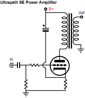
Zero PSRR Frontend for Ultrapath
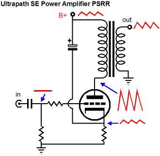
The huge problem, of course, is that all the B+ voltage noise is coupled to the output tube's cathode, where the ripple is treated as signal to be amplified.
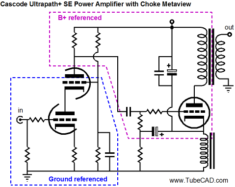
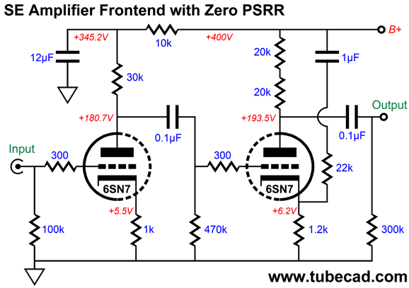
The only two ways to sidestep this problem are either to have a truly noise-free high-voltage power supply (good luck) or to ensure that 100% of the power-supply noise appears at the output tube's grid, which effectively makes the output stage B+ voltage referenced, rather than ground referenced. Here is an example with a cascode input stage.
The cascode input stage offers a PSRR of nearly zero, which works well with this ultrapath amplifier. Since the output tube and output transformer see 100% of the power-supply ripple, they effectively see zero ripple, much in the same that while you sit in an airplane traveling at 400mph, you do not notice that the coffee in your cup is moving at 400mph—as far as your mouth is concerned, it isn't moving at all.
Assuming that two triodes in cascade are used, an input stage and a driver stage, the driver stage must offer a PSRR of zero. In other words, the driver stage must pass 100% of the power-supply noise along with the music signal to the output tube's grid. The new problem we run into is that triodes present a relatively low plate resistance (rp), so the plate resistor and the triode's plate resistance form a two-resistor voltage divider, which means that we will always get a PSRR greater than zero. One workaround is to inject a small portion of the power-supply noise into the driver triode's cathode, so the ripple will be amplified with no phase inversion, bringing the PSRR down to zero.
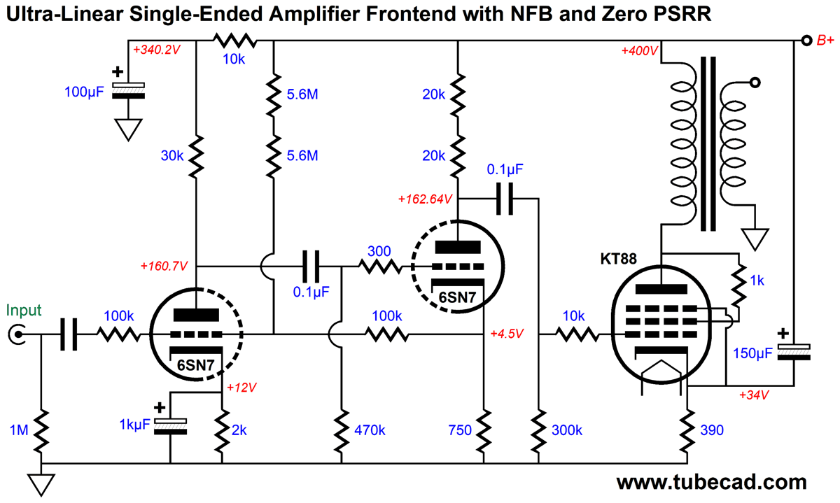
The 12µF and 0.1µF (the internal coupling capacitor) and 1µF are interrelated, so we cannot change on value without having to charge the other two. This arrangement works well, but it does not let us apply a negative feedback loop across the two frontend triodes. Why would we want to apply negative feedback? Two reasons: lower gain and lower distortion. A triode-connected KT88-to-KT120 output tube requires far less input signal to achieve full output than does a 300B. The circuit shown above realizes a gain of 1:107, which would work well with the 300B, which will require close to 80Vpk of grid signal. In contrast, a KT88 only needs about 33Vpk to be driven to full output.
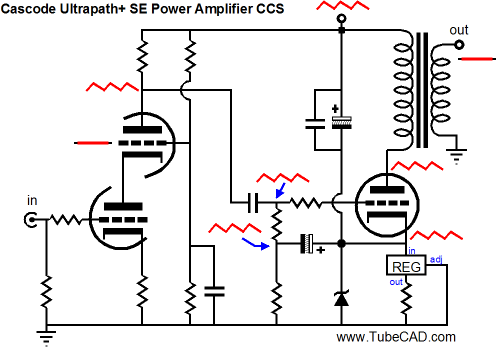
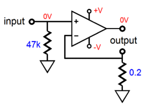
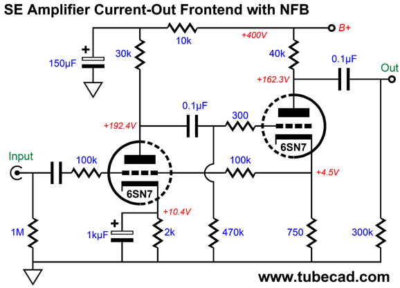
This got me thinking about converting the two-triode frontend into a current-out amplifier, which does use a negative feedback loop, but the loop terminates at the driver triode's cathode, not its plate.
The input stage strives to establish an inverted signal upon the driver triode's cathode. To see how this works imagine that we forced an external positive voltage pulse on the output at the plate of the driver tube. This pulse will cause the driver triode to draw a bit more current, as it now sees a higher cathode-to-plate voltage. As the cathode resistor is in the same current path as the triode, the cathode voltage increases slightly, prompting the input triode to experience a high grid voltage, producing a negative-going pulse at its plate, this travels to the driver triode's grid via the internal coupling capacitor, decreasing the driver current flow. The result is the driver triode offers very little countervailing current change to the pulse. In other words, the driver triode's plate resistance has increased dramatically due to the negative feedback loop. All of this is a move in the right direction, but we still do not achieve a PSRR of zero. The workaround is to inject a small portion of the power-supply noise into the input stage's grid.
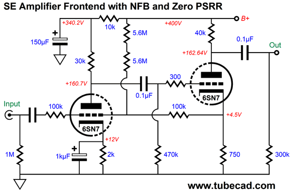
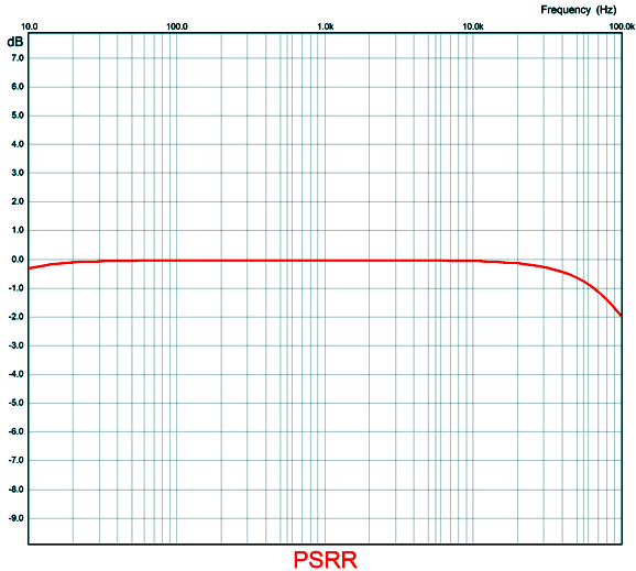
The added 5.6M resistors bring the PSRR down to zero. Note that the resistor string is DC coupled to the B+ voltage, which helps explain why the two resistors are placed in series, as some carbon-film resistors are rated for only a 250V maximum working-voltage. For example, each 5.6M resistor will dissipate only 7 milliwatts, but see a near 200-volt voltage drop. The gain for this frontend comes in at 1:33, which is enough for the EL34 and KT88 triode-connected power tubes. It is an odd situation to be striving to obtain a PSRR of zero after having sought the highest PSRR possible. Here is the PSRR versus frequency graph.
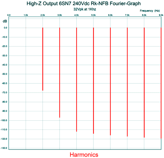
The PSRR is flat to within 0.1dB from 20Hz to 20kHz. Next, let's look at the SPICE-generated Fourier graph at full output from the frontend.
Very clean indeed with a lovely single-ended cascade of harmonics. The THD is below 0.1%. What I love about this circuit is that it could have been designed and built in 1940, as no recent device is needed, not even 1% metal-film resistors. Okay, let's put the entire amplifier together now.
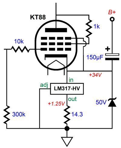
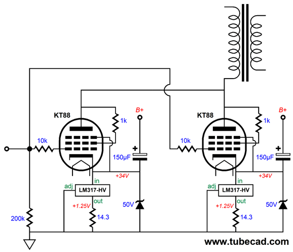
The KT88 plate dissipation is 32W and its cathode resistor dissipates 3W, so I would use at least a 5W resistor. In fact, we could replace the cathode resistor with a constant-current source based on an LM317-HV positive, adjustable voltage regulator IC.
The constant-current source works much better at decoupling the ground from the KT88 cathode and provides auto-bias functionality, a win-win situation. The zener is a protection device that prevents the regulator from seeing too high a voltage at start-up and allows a discharge path for the 160µF of capacitance (the 150—F capacitor bypassed with a 10µF film or PIO capacitor) at shut-off. After more than two decades of writing about tube circuits here, I know that I must spell out the justification for every essential part, as many readers leave out of their projects any part whose purpose they fail to grasp—then I get an angry email. I wish it were otherwise. If the zener is left out of the circuit, and especially if the output tube is missing from its socket, the LM317-HV will die at turn-on, as the large 150µF decoupling capacitor will pull the LM317-HV input pin up beyond its maximum voltage limit. Overall, I think that this would be a fun single-ended power amplifier to build. I would double-up on the KT88 tubes, which would allow us to run them with a slightly lighter idle current, say 75mA. The problem we would then face is that the 300k grid resistor would be too high in value. If we reduce its value to 200k, then we must lower the 5.6M resistor values down to 4.7M to achieve a PSRR of zero.
The gain drops a wee bit, down to 1:31, still enough to drive the output tubes with 1Vpk of input signal. Note how each KT88 cathode gets its own constant-current source and decoupling capacitor to the B+ voltage. This makes tube matching less critical and allows for tube aging.
Music Recommendation: //JRB
Very few can imagine just how much hard work is required to make one of my posts. If you have any sort of inkling or intuition of what is involved, please think about supporting me at Patreon.
User Guides for GlassWare Software
For those of you who still have old computers running Windows XP (32-bit) or any other Windows 32-bit OS, I have setup the download availability of my old old standards: Tube CAD, SE Amp CAD, and Audio Gadgets. The downloads are at the GlassWare-Yahoo store and the price is only $9.95 for each program. http://glass-ware.stores.yahoo.net/adsoffromgla.html So many have asked that I had to do it. WARNING: THESE THREE PROGRAMS WILL NOT RUN UNDER VISTA 64-Bit or WINDOWS 7, 8, and 10 if the OS is not 32-bit or if the OS is 64-bit. I do plan on remaking all of these programs into 64-bit versions, but it will be a huge ordeal, as programming requires vast chunks of noise-free time, something very rare with children running about. Ideally, I would love to come out with versions that run on iPads and Android-OS tablets.
|
I know that some readers wish to avoid Patreon, so here is a PayPal donate button instead. Thanks. John Broskie
John Gives
Special Thanks to the Special 84
I am truly stunned and appreciative of their support. In addition I want to thank the following patrons:
All of your support makes a big difference. I would love to arrive at the point where creating my posts was my top priority of the day, not something that I have to steal time from other obligations to do. The more support I get, the higher up these posts move up in deserving attention.
If you have been reading my posts, you know that my lifetime goal is reaching post number one thousand. I have 460 more to go. My second goal is to gather 100 patrons. I have 17 patrons to go. Help me get there.
Only $9.95
The Tube CAD Journal's first companion program, TCJ Filter Design lets you design a filter or crossover (passive, OpAmp or tube) without having to check out thick textbooks from the library and without having to breakout the scientific calculator. This program's goal is to provide a quick and easy display not only of the frequency response, but also of the resistor and capacitor values for a passive and active filters and crossovers. TCJ Filter Design is easy to use, but not lightweight, holding over 60 different filter topologies and up to four filter alignments: While the program's main concern is active filters, solid-state and tube, it also does passive filters. In fact, it can be used to calculate passive crossovers for use with speakers by entering 8 ohms as the terminating resistance. Click on the image below to see the full screen capture.
Tube crossovers are a major part of this program; both buffered and un-buffered tube based filters along with mono-polar and bipolar power supply topologies are covered. Available on a CD-ROM and a downloadable version (4 Megabytes). Download or CD ROM To purchase , please visit our Yahoo Store:
What we believe is not intentionally isomorphic with what is actual
Tautologies are tautological—and boring
Love is the the desire for and generation and birth in beauty. — Plato
Science is a method, not a repository of wisdom and truth
Justice is conflict (strife, war)
—
Heraclitus
Water is water, nothing more. Beer and wine are something more.
Advertising one's imagined moral and intellectual superiority is both tedious and off-putting. —Me
|
|||


| www.tubecad.com Copyright © 1999-2021 GlassWare All Rights Reserved |