| John Broskie's Guide to Tube Circuit Analysis & Design |
22 October 2020 Post Number 517
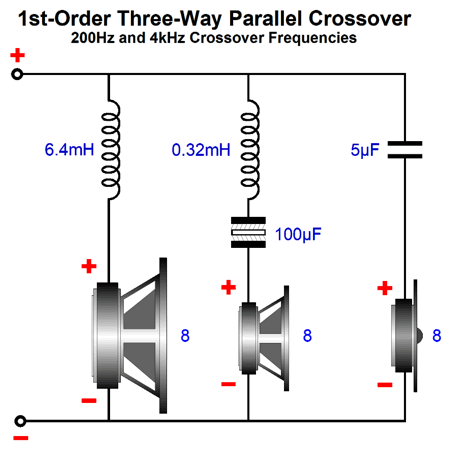
Loudspeaker Crossovers with Polarized Capacitors The batteries are not the cost-prohibitive part of this setup, but the crossover capacitors, as we must use two capacitors at twice the value of the non-polarized crossover capacitor, as two capacitors in series halve the capacitance, unlike resistors, which double in resistance. Here is an example of a stock three-way 1st-order crossover.
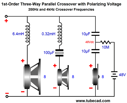
The tweeter capacitor is 5µF in value and results in 4kHz high-pass filter with the 8-ohm tweeter. Now, let's look at the polarized version.
Two 10µF capacitors have replaced the single capacitor. The 48V battery applies its polarizing voltage through the 1M resistor. The battery doesn't power anything beyond the few seconds required to charge up the two 10µF capacitors, which will produce a minuscule and brief warming of the 10M resistor. Once charged, the battery will last as long as its advertised shelf-life (up to seven years for quality batteries), as its working days are over. By the way, the battery's voltage need only be a bit higher than the highest expected peak voltage swing into the loudspeaker. For example, 100W into 8-ohms results in 40Vpk, so a 48V battery is adequate. In contrast, a 16W single-ended amplifier only puts out 16Vpk, so two 9-volt batteries in series would work; a 4W flea-power amplifier, 8Vpk, so one 9-volt battery.
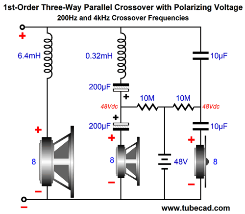
By the way, we don't have to use batteries, as we can use a 48V switcher wallwart power supply. You might be nervous about the switcher screwing up the sound, due to its high-frequency switching. I worry more about how the switcher is grounded relative to the house ground. Well, this may not prove all that important. Here is why: high-quality film capacitor retain a charge for an amazingly long time. I charged up two polypropylene capacitors (1µ and 10µF) to 60V and then measured them the next day. Both had only lost 5 volts. In fact, I am not sure that they had actually lost any voltage, as the voltmeter so quickly discharged them that it is likely that the charge was closer, far closer, to 60V the next day. This means that we could just plug the power plug into the back of the speaker for a second or two and then break the connection until our next listening session. Indeed, we could devise a circuit that monitored the capacitor voltage and only quickly charged up the capacitors once a threshold voltage had been reached and then disconnect. By the way, note that in the design example, the midrange's 100µF non-polarized electrolytic capacitor didn't get a polarizing treatment. Why not? I am not sure that this type of capacitance would benefit from a polarizing voltage. Perhaps, we could replace the single capacitor with two 200 µF polarized electrolytic capacitors in series, say a high-frequency type, such as the Panasonic FM or FC or FR series capacitors. One problem I would expect to encounter is the electrolytic capacitor's leakage current would eventually drag down a battery, so an external power supply would be needed. By the way, long ago, I read an article on a radio design that pointed out that electrolytic capacitors could be used in place of mica and film capacitors, if a polarizing voltage was applied, as the bias voltage greatly extended the capacitor's high-frequency bandwidth.
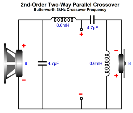
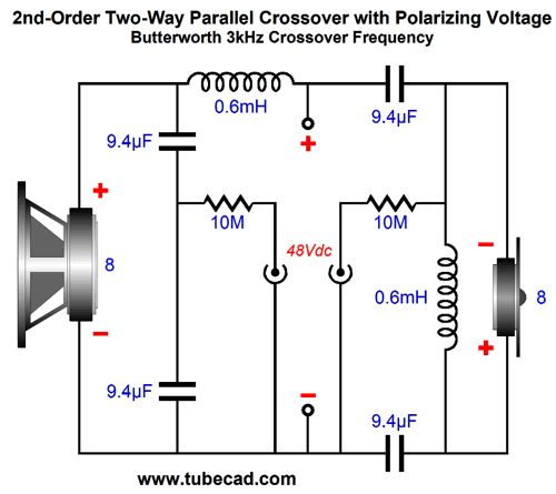
Okay, what about 2nd and 3rd order speaker crossovers? Here is a stock 2nd-order, two-way crossover.
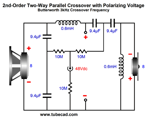
All we need to do is to replace each 4.7µF capacitor with two 9.4µF capacitors in series and apply a polarizing DC voltage.
Here we see a DC power jack that accepts the 48Vdc from a wallwart switcher power supply. By the way, we can move one of the 9.4µF to the bottom of the tweeter and inductor.
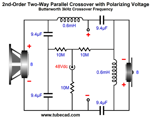
This crossover performs exactly like the previous example. The only real difference is that the inductor and tweeter and their wires now see the 48Vdc polarizing voltage. In the interest of symmetry, we can split the woofer's inductor as well.
Once again, the exact same performance obtains. So why bother? Aesthetics makes its own dictates. This layout looks more balanced, so it is intellectually more pleasing. At the same time, there might be lower DCR from two inductors than one, or, perhaps, two smaller inductors might be easier to place on a PCB. One question worth asking is, Will the two crossover filters interact with each other due to the 10M polarizing resistors? I doubt it, but we could play it safe by using two DC power jacks per loudspeaker cabinet. Before sitting down to listen, we would plug in one jack briefly, then the next.
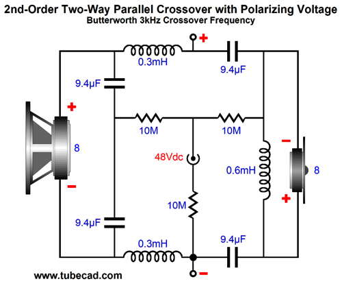
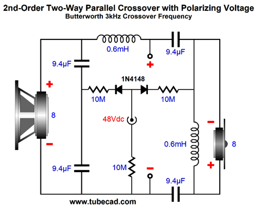
How about this idea: we leave the external power supply constantly engaged, but we add two diodes to isolate the two crossover filters.
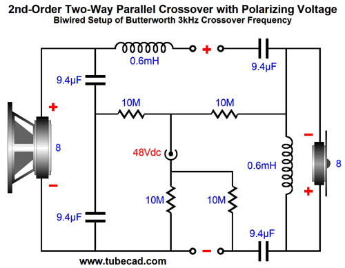
The two 1N4148 signal diodes are insanely fast and tiny. Speaking of separation, what about a bi-wired crossover?
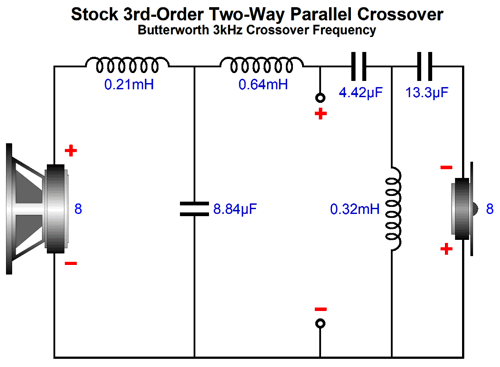
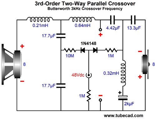
If the loudspeaker attaches to only one power amplifier, then all the previous polarized configurations will still work. On the other hand, if you are also bi-ampping with two mono-bloc power amplifiers, then the setup shown above is needed. The four 10M resistors establish a DC path for both of the separate filters. Okay, what about 3rd-order crossovers? We could just double up on all the capacitors, but complex crossover can hold a lot of capacitors. Thus, it behooves us to try to retain as many preexisting capacitors as possible.
Note that the 4.42µF and 13.3µF capacitors are already in series with each other. If only we could charge the two up without the 0.32mH inductor shorting our efforts. Well, here is one possible workaround.
The added 2kµF/50V electrolytic capacitor largely behaves as an AC short, while still blocking the flow of DC. Why did I use a 1M resistor for the tweeter section and a 10M for the woofer section? I worry about the electrolytic capacitor's leakage current dragging down the polarizing voltage. Of course, the best route is to perform a quick experiment, using a 1M resistor and 2kµF electrolytic capacitor and 48Vdc power supply. We hook up all three and measure the voltage drop across the capacitor. If it measures 48V, then we try the 10M resistor in its place.
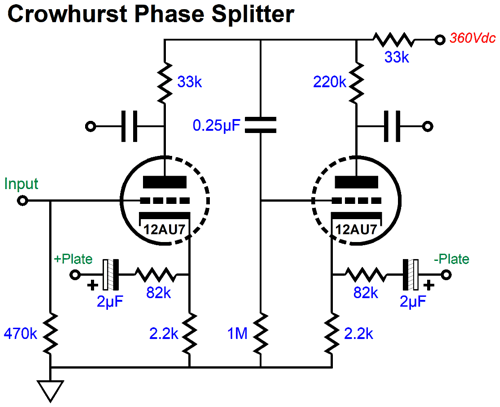
Crowhurst Phase Splitter
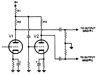
In addition, his article laid out an interesting push-pull power amplifier design. For example, he used two negative feedback loops, one local and the other global. As I looked over his schematic, I noted what I thought must be an error, as his phase splitter seemed way off base.
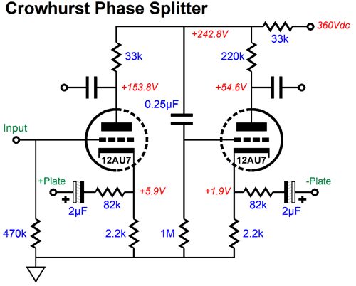
Note the 220k plate resistor for the triode on the right. Surely, this value was a mistake. I ran SPICE simulations and the results were grim. I guessed that he had missplaced a decimal place, so I tried a 22k value instead. Also grim. Here are the voltage relationships with his original part values.
Grotesquely asymmetrical. Worse, his plan of using the two 82k negative-feedback resistors to lower the output pentode's distortion and output impedance must fail, as the right side produces far more gain than the left side. The only way his setup would work is if both plate resistors shared the same value—otherwise the negative feedback ratios would be off, because the left triode produces so much more gain than the right triode. In SPICE, I tweaked the right plate-resistor value until I got the best output signal balance.
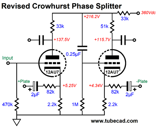
This gets us closer, but we still have problems. A phase splitter that converts an unbalanced input signal into a balanced output must achieve three goals. The first is, obviously, good balance between the output phases; in other words, equal magnitudes, but inverted phase. The second is that the two outputs should offer the same bandwidth. And the third is that the outputs promote a good PSRR; in other words, both outputs should present the same amount of power-supply noise and in phase, so that the next stage, usually a push-pull output stage, can ignore the power-supply noise, since it is a common-mode signal. Crowhurst's phase splitter failed at all three. I decided to forgo the two negative feedback loops and to use a common cathode resistor.
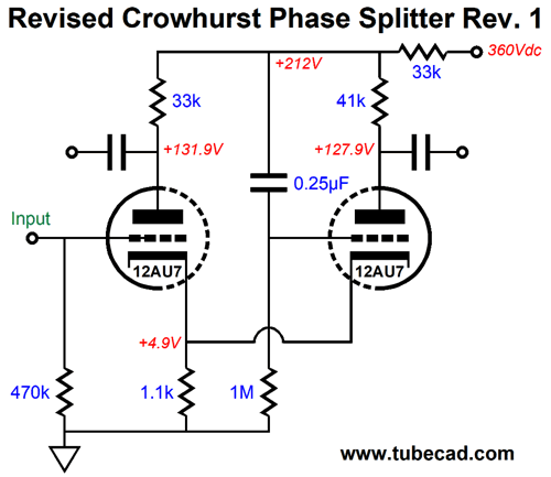
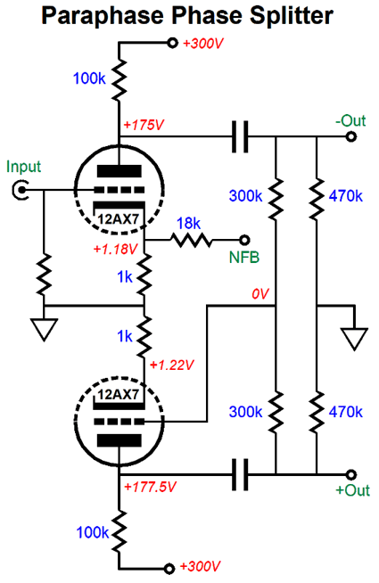
The balance was good with the 41k plate resistor. By the way, if you are wondering how one might source a 41k resistor, since that is not a common resistor value, the answer is that we place two 82k resistors in parallel. Let's pull back and try to understand what Crowhurst had in mind. His phase splitter is ultimately a variant of the paraphrase phase splitter, which explains why the circuit uses a 33k series resistor to attach to the B+ voltage, rather than terminating directly. Any imbalance in output signals will create an error signal at the nexus of the plate resistors and the 33k resistor to the B+ voltage. The 0.25µF capacitor relays this error signal to the right triode's grid, which allows the right triode to correct the imbalance. Okay, let's supercharge the circuit.
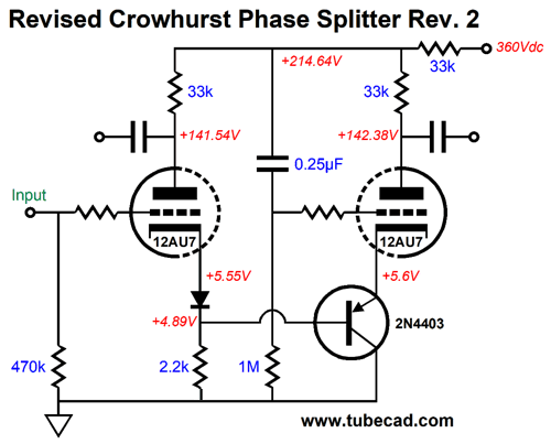
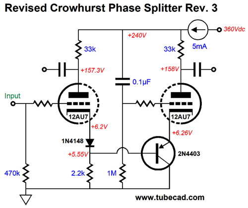
The PNP transistor faithfully relays the left triode's cathode signal to the right triode's cathode. The 1N4148 signal diode serves to make up for the PNP transistor emitter-to-base voltage drop. Both plate resistors share the same value and the balance is excellent. Alas, the PSRR is poor. The workaround is to replace the 33k series resistor with a constant-current source, which will promote better balance and shield the phase splitter from power-supply noise.
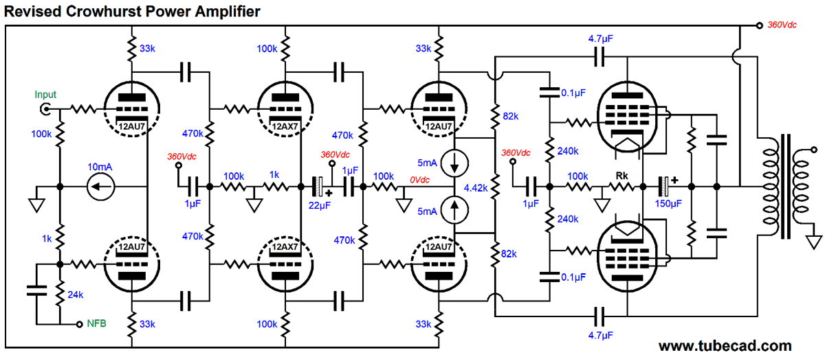
What about the two local negative feedback loops? Can they be reintroduced? No. Since we resorted to adding a constant-current source, however, we could use them to redeem Crowhurst's goals. Speaking of his goals, I was stunned to see so much open-loop gain being realized. His amplifier's input stage consisted of two 12AX7-based grounded-cathode amplifiers in cascade. Assuming a gain of 1:50 from each, we are looking at a combined gain of 1:2,500. Mercy, that's a lot of gain. In days past, negative feedback was seen as being like gold: you could never have too much. Today, we take a more sober stance towards negative feedback: if it doesn't cause more problems than it fixes, it's okay; otherwise, not. Here is a remake of his amplifier that seems far more sane to me.
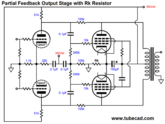
Three solid-state, low-voltage constant-current sources are used. The input stage both offer signal gain and phase splitting. The 10mA constant-current source proves a godsend in this application. One interesting feature of the differential amplifier with constant-current source cathode loading is that the output PSRR is close to zero; in other words, no power-supply rejection. Well, we can take this seeming liability and run with it, transforming it into a feature. (I cannot imagine a more American sentence.) Other than the input signal and the negative feedback connection, which are both ground referenced, the rest of the power amplifier is B+ voltage referenced. Note how the local negative feedback loop never terminates into ground; instead, the 4.42k resistor replaces the two 2.2k cathode resistors, which greatly enhances CMRR in the driver stage. In AC terms, the two constant-current sources are not there, so the two 82k negative feedback loop resistors and the 4.42k resistor form a low-loss balanced negative feedback loop. By the way in SPICE simulations, I noted that low-frequency peaking was evident. The workaround is to carefully tweak the internal coupling capacitor and negative feedback capacitor values. Another workaround is to use a partial-feedback topology.
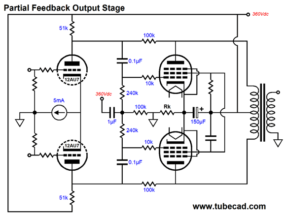
This arrangement produces the same gain as the cathode-feedback version, but does not require capacitors to attach to the plates. Note the 51k and 100k in parallel come close to equaling 33k. This alternative topology retains the same PSRR trick of being B+ voltage referenced.
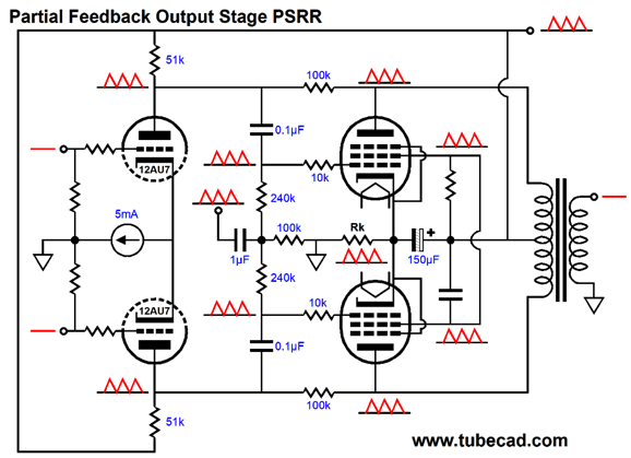
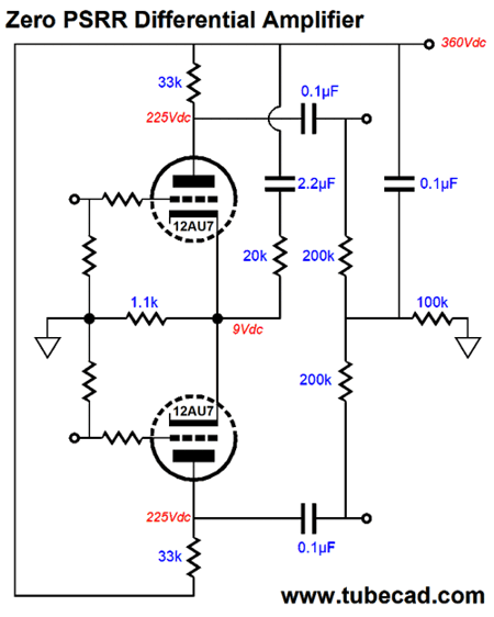
The output pentode's cathode, grid, screen grid, and plate all see 100% of the power-supply noise; thus, they ignore the noise, much in the same way you ignore that you are traveling at 400 MPH in a jet, as you and your coffee and seat and book are also traveling at 400 MPH. I know that for some readers things went bad once I introduced the solid-state constant-current sources, as they insist on pure-tube technology. Well, never let it be said that I am not accommodating. Here is a solid-state-free variation of the differential amplifier with zero PSRR.
This circuit could have been designed in 1920, if anyone thought the way I do. The 20k resistor injects enough power-supply noise into the joined cathodes to force a PSRR of zero. The next step is to incorporate this circuit inside the output stage.
In terms of total performance, the version with the constant-current source wins, as the constant-current source provides far better CMRR. On the other hand, in this application, we are relying on the output transformer to provide CMRR, as the transformer is an intrinsically differential device that only passes differences.
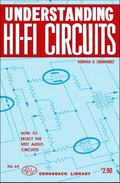
The following is an excerpt from Crowhurst's book, Understanding Hi-Fi Circuits.
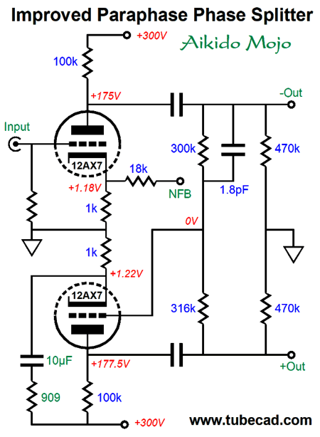
Paraphase Phase Splitter
The top triode defines a grounded-cathode amplifier, while the bottom triode defines an anode follower that simply inverts the signal present at the top triode's plate. The top triode defines a grounded-cathode amplifier, while the bottom triode defines an anode follower that simply inverts the signal present at the top triode's plate.
As we can see, we get fairly good but not perfect balance, as the bottom triode fails to match the top triode's gain. Next, we examine the frequency of the two output phases.
As we can readily see the anode follower's high-frequency bandwidth falls compared to the grounded-cathode amplifier's bandwidth. The last test is of the phase splitter's potential to yield a fine PSRR. This is a bit subtle, as we are not actually concerned with the PSRR of the two triodes, but the measure of how closely they match in ripple output. Phase splitters are seldom standalone circuits; instead, they usually drive a balanced stage, such as a push-pull output stage. As long as the amount of leaked ripple at both outputs match in both magnitude and phase, the driven balanced stage will apply its CMRR to ignore the ripple. In contrast, if the magnitudes or phase relationships are off, the leaked power-supply noise will be treated by the driven balanced circuit as signal to be amplified.
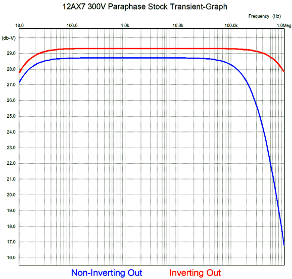
In this test, the input was grounded and the B+ voltage experienced a 1Vpk 1kHz superimposed sinewave. Ideally, the plot line would have been a flat line; instead, we see 60mV of ripple that cannot be flattened by CMRR. Okay, here is my quick remake of the paraphase circuit.
I count three changes: a 316k resistor replaced the 300k feedback resistor, a 1.8pF capacitor shunts the anode-follower's input 300k resistor, and a pair of Aikido mojo parts (the 10µF capacitor and 909 ohm resistor) were added. The first change improved the output balance; the second, the high-frequency bandwidth; and the third, the PSRR potential. Let's see how well these changes worked. First, the balance test.
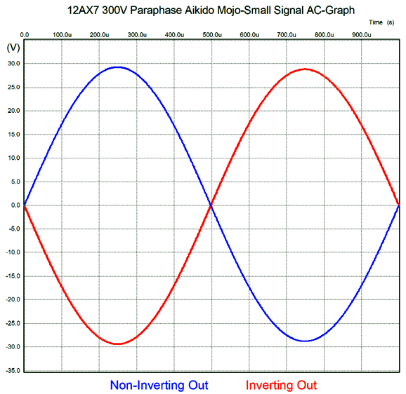
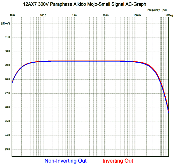
Much better. Next, the high-frequency bandwidth gets tested.
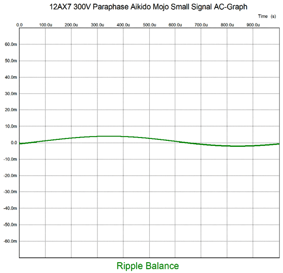
Dang close. Last, we test the difference in power-supply noise leakage.
The improvement over the stock circuit is at least 15 fold, which is about a 23dB improvement.
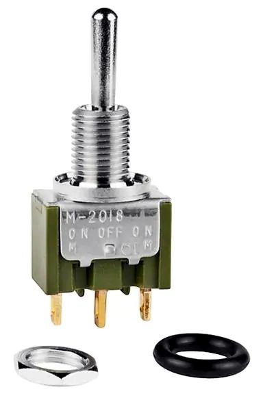
Tube Power Amplifier Input Switch
The important detail is that the toggle switch must hold gold contacts, not silver, not brass, not nickel-plated iron. The other toggle type will work at first, but will fail with time, as the tiny signal is not powerful enough to "clean" the contacts the way 120Vac at 1A would. The way you discern if a toggle switch holds gold contacts is to search for its current rating. Gold contacts are rated for only 100mA or so, not 1A; 28Vac, not 230Vac. in addition, a gold-contact switch cost far more than its less noble brothers. They are often labeled either "Logic Level" or "Signal Level." Here is an example, a NKK Switches model M2013SS1G01. Note the gold-plated solder pins.
Music Recommendation: Blackbirds LaVette summons the astounding ability to make any song she sings sound profoundly personal and seemingly autobiographical; for example, even the famous Moody Blues song, "Nights In White Satin," from her Interpretations: The British Rock Songbook album sounds intimate and confidential leaving her lips. A staggering talent. Note that the recording label is Verve. I would classify this album as belonging more in Jazz Vocals, rather than Rhythm and Blues. Amazon Music offers the album in 24-bit/96kHz resolution. Well worth hearing.
//JRB
User Guides for GlassWare Software
For those of you who still have old computers running Windows XP (32-bit) or any other Windows 32-bit OS, I have setup the download availability of my old old standards: Tube CAD, SE Amp CAD, and Audio Gadgets. The downloads are at the GlassWare-Yahoo store and the price is only $9.95 for each program. http://glass-ware.stores.yahoo.net/adsoffromgla.html So many have asked that I had to do it. WARNING: THESE THREE PROGRAMS WILL NOT RUN UNDER VISTA 64-Bit or WINDOWS 7, 8, and 10 if not 32-bit or any other 64-bit OS. I do plan on remaking all of these programs into 64-bit versions, but it will be a huge ordeal, as programming requires vast chunks of noise-free time, something very rare with children running about. Ideally, I would love to come out with versions that run on iPads and Android-OS tablets.
|
I know that some readers wish to avoid Patreon, so here is a PayPal button instead. Thanks. John Broskie
John Gives
Special Thanks to the Special 89 To all my patrons, all 89 of them, thank you all again. I want to especially thank
I am truly stunned and appreciative of their support. In addition I want to thank the following patrons:
All of your support makes a big difference. I would love to arrive at the point where creating my posts was my top priority of the day, not something that I have to steal time from other obligations to do. The more support I get, the higher up these posts move up in deserving attention.
If you have been reading my posts, you know that my lifetime goal is reaching post number one thousand. I have 483 more to go. My second goal was to gather 1,000 patrons. Well, that no longer seems possible to me, so I will shoot for a mighty 100 instead. Thus, I have 11 patrons to go. Help me get there.
Support the Tube CAD Journal & get an extremely powerful push-pull tube-amplifier simulator for TCJ Push-Pull Calculator
TCJ PPC Version 2 Improvements Rebuilt simulation engine *User definable
Download or CD ROM For more information, please visit our Web site : To purchase, please visit our Yahoo Store: |
|||||||||||||||||||||||||||


| www.tubecad.com Copyright © 1999-2020 GlassWare All Rights Reserved |