| John Broskie's Guide to Tube Circuit Analysis & Design |
|
03 July 2020 [Updated July 4th] Post 507
Four-Triode Cascade
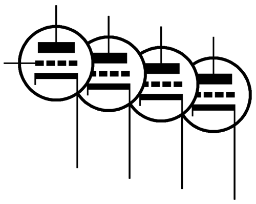
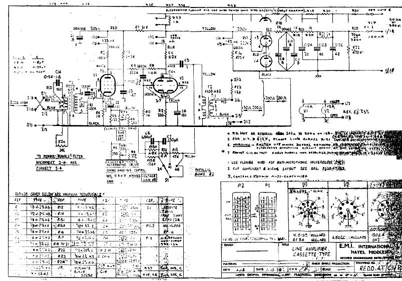
In addition, when you place three grounded-cathode amplifiers in series along with a cathode follower output stage, the phase shifts begin to add up and negative feedback becomes less stable. Now, the REDD.47 used a triode-based anode-follower stage after the input pentode stage. What if we double up this topology, in other words, the lineup I envisage would be grounded-cathode amplifier followed by two anode followers in series, the last of which would hold a cathode follower. The input stage grounded-cathode amplifier would run open loop, while the next two stages held negative feedback loops.
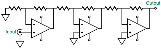
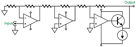
Sure it looks complicated, but much of it is duplicated. In other words, the two anode-follower stages are in series. Here is a translation into OpAmps.
All three tube stages are inverting, but the input OpAmp isn't. Since there is an odd number of tube stages, the output signal's phase is inverted, which explains the inversion of the output transformer primary. We can further the translation from vacuum to silicon by adding an emitter follower stage.
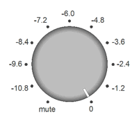
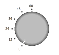
The NPN transistor based emitter follower's output is contained within the last stage's negative feedback loop, just in the same way as the cathode follower is contained by the last anode-follower stage's negative feedback loop. In the REDD 47 circuit, the output transformer is a step-down type, which yields a huge decrease in output impedance, but at the expense of wasted gain. In contrast, with the cathode follower output stage, the output impedance will prove plenty low. Indeed, because of the second anode-follower negative feedback loop encompassing the follower's output, even lower still. Thus, I bet that we can get away with a 1:1 isolation output transformer, which will offer less distortion and wider bandwidth. Assuming an input signal transformer with a winding ratio of 1:10, we start with a gain of 20dB. The grounded-cathode amplifier first stage delivers a gain of 20 (+26dB). The two anode-follower stages bring the total gain up to 80dB (1 to 10,000). The REDD 47 offered two volume attenuators, one fine and one coarse. Sadly, the fine was too fine, while the coarse was too coarse. A better arrangement would be place a stepped attenuator with -1dB steps at the input transformer's secondary; and insert a six-position stepped attenuator with -12dB steps within the anode-follower gain stages.
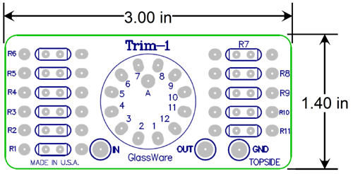
The input stepped attenuator could easily be made with one of my Trim-1 11-position stepped attenuators.
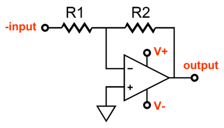
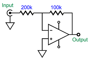
The coarse stepped attenuator is more subtle. By varying the ratio between the two resistances in the negative feedback loop we set the amount of gain realized. In fact, unlike a non-inverting negative feedback loop arrangement, the inverting arrangement allows for actual attenuation, not just a reduction in gain. The following arrangement reduces the input signal amplitude by half (-6dB) at the output.
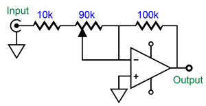
Making an adjustable amount of gain is easy enough.
At one extreme of the potentiometer, we get unity gain, as the 10k and 90k resistances add to 100k. At the other extreme, we get a gain of 10 (+20), as 100k/10k equals 10. We could use a stepped attenuator on each of the two anode-followers, but three volume controls seems excessive, although I must admit that this three-knob setup would deliver the most control.
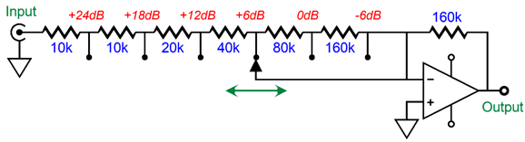
Actually, we can use the two stepped attenuators, but place them on a single two-pole, six-position rotary switch. Our goal is -12dB steps, so each stepped attenuator must offer -6dB steps, as the two attenuations add. Fortunately, -6dB steps makes for easy math, as each step presents a halving of the signal.
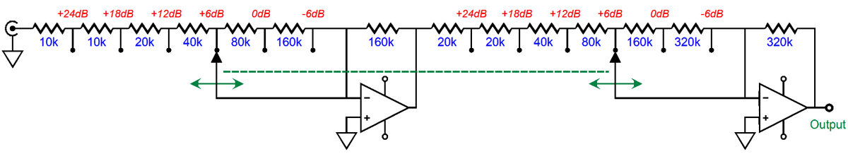
When the stepped attenuator switch is full on, the inverting amplifier sees 10k and 160k in its negative feedback loop, resulting in a gain 16 (+24dB). At the other extreme, the gain fall to 0.5 (-6dB), as the negative feedback loop contains two resistances, 320k and 160k. Cascading two anode-followers is easy enough.
Note that the second anode-follower attenuator gets higher valued resistor by a factor of 2. Why? With the higher gain, we are less concerned with noise from the resistors. In fact, if we were willing to go hybrid, we could replace all the plate resistors with constant-current sources, which would allow us to run a much lower B+ voltage and would deliver far better PSRR. Wit the constant-current sources in place, we could lower the first anode-follower's feedback resistor values even more and not lose gain.
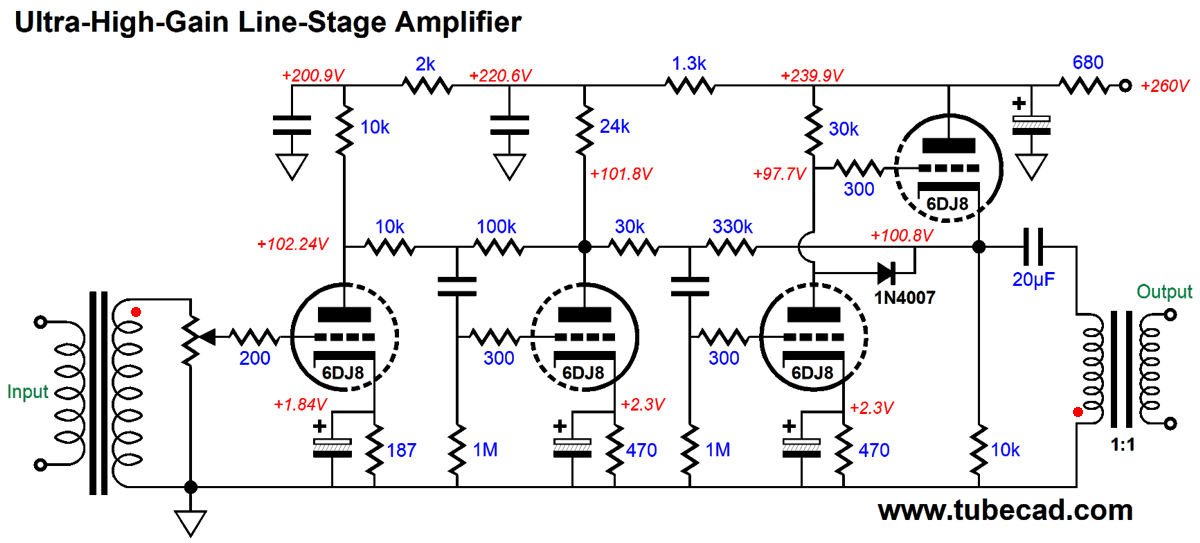
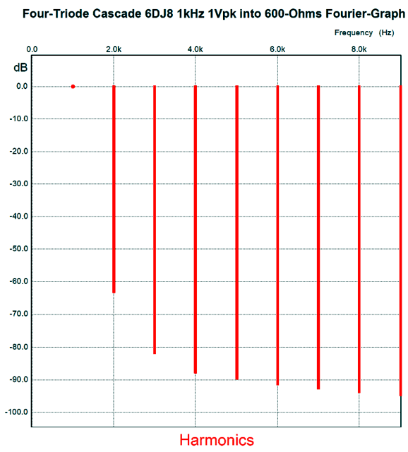
Just two 6DJ8/E88CC tubes and two signal transformers. Put it all in a fancy box and slap a $5,000 price tag on it and you are set. Perhaps, I am jumping the gun here. How does the circuit perform? Let's start with the output impedance of 30 ohms. The distortion at 1Vpk @ 1kHz is below 0.1%, with a lovely single-ended harmonic structure. The PSRR is better than 60dB.
Not bad, when you consider the gain of 60dB (1:1,000) and the 600-ohm load.
Broskie Source Follower
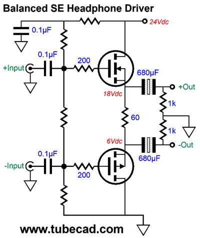
The two power MOSFET run in strict class-A, single-ended mode. The shared 60-ohm load resistor sets an idle current of 200mA, which implies an output voltage swing of 6.4Vpk into 32-ohm headphones. Plenty loud, as 6.2Vpk implies 640mW of power. The only thing I don't like is that none of my four low-impedance headphones holds balanced termination. This got me to try to think of a circuit that would convert the balanced input signal into an unbalanced output signal strong enough to drive 32-ohm loads. Why not try a Broskie source follower, I thought.
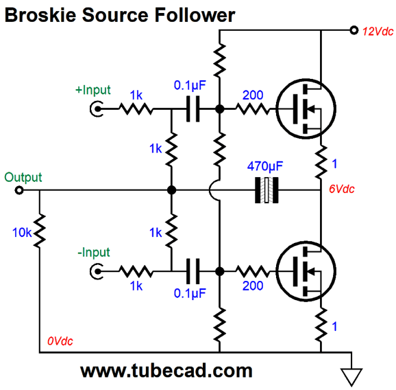
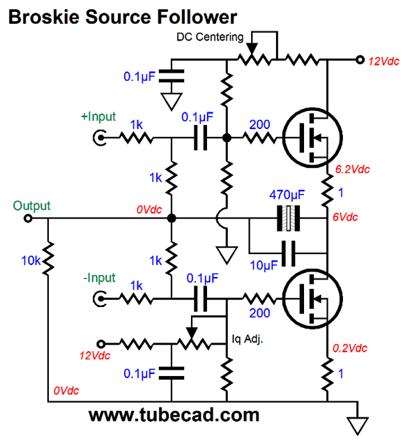
Just like the Broskie cathode follower circuit, this MOSFET version converts the balanced input signal into an unbalanced output signal. Moreover, it matches the Broskie cathode follower's gain, i.e. 0.5 (-6dB). In other words, given 1Vpk of input signal from each phase of the balanced input signal, we get 1Vpk of output, not the 2Vpk that the typical differential amplifier yields. Since we are driving two naked MOSFETs, we run into the same problem the Pass Zen amplifier faces: high input capacitance from the MOSFETs, which require low-resistance negative feedback loop resistor values to get decent high-frequency bandwidth. Fortunately, the balanced DAC output should be able to drive 600-ohm loads, so we are not as constrained as you might imagine. In addition, the MOSFET dissipate relatively low heat, so smaller devices can be used, which offer correspondingly low input capacitances. It's a win, win throughout. To make this circuit more user-friendly, I added two potentiometers, one for setting the idle current, the other for centering the MOSFETs to half the B+ voltage.
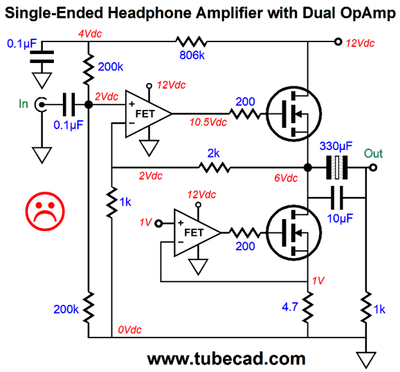
I first center the output stage, then set the desired idle current, and then set the centering again. As this circuit runs I pure class-A, push-pull we can expect to get twice the idle current as the peak output current. I didn't specify all the resistor values, as they depend on the MOSFETs used. I would try the IRF630 MOSFET. Why? Somewhere I have a bunch of them. More importantly, they offer relatively low input capacitance, just 540pF. While on the topic of making use of switcher wallwarts to drive headphones, I have a bunch of orphaned 12Vdc wallwarts, which came with external hard-drives, printers, modems... Why not make a single-ended headphone amplifier?
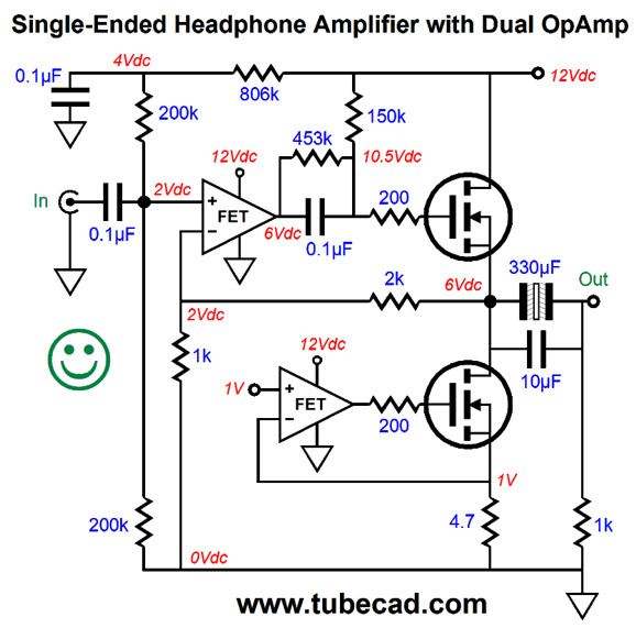
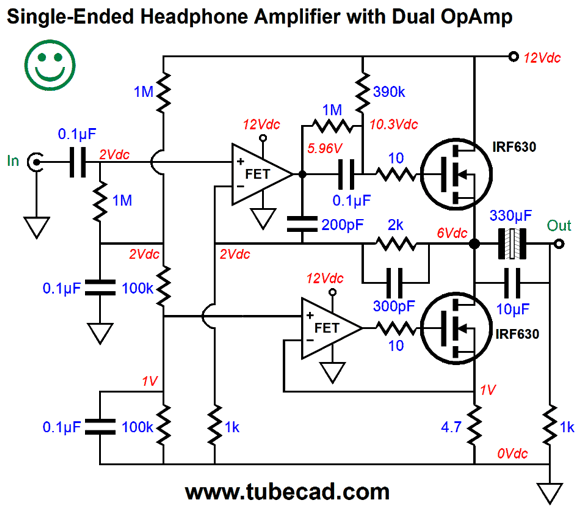
The bottom OpAmp controls the current flow through the bottom MOSFET, resulting constant-current conduction from the device. The top OpAmp controls the top MOSFET, which runs as a source follower. The gain is set by the 1k and 2k resistors, resulting in a gain of 3, as (1k + 2k)/1k equals 3 (+9.5dB). There's only one problem: we would be lucky to get more that 1V of peak positive output voltage swing from it. Why? The top OpAmp's output can only swing so far to the positive power supply voltage. Enhancement-mode MOSFETs, of the non-lateral type, require a relatively high turn-on gate voltage. Inother words, the top OpAmp cannot swing high enough positively to drive the top MOSFET. Here is the workaround.
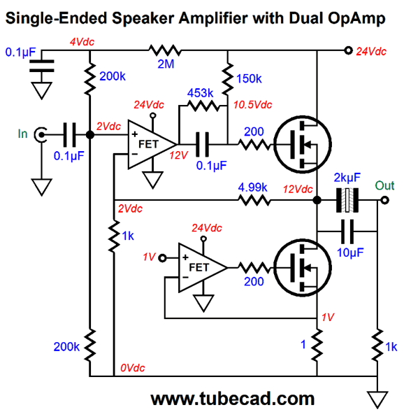
The added internal coupling capacitor that is shunted with the 453k resistor allows the top OpAmp to center its output at 6Vdc, while still prompting the top MOSFET to conduct heavily enough for class-A operation. By the way, the 4.7 ohms source resistor sets the current flow to 213mA, so we could expect peak current swings of 200mA. Before anyone asks, yes this topology could be scaled up to drive speakers, rather than headphone. First we would use a 24Vdc switcher and up the current flow to at least 1A by replacing the 4.7-ohm source resistor with a 1-ohm resistor. The 1A idle current would deliver 4W into 8-ohm loads. Next, we would replace the 2k feedback resistor with a 4.99k resistor. I would use an OPA2107 dual OpAmp, as it sounds quite tube-like.
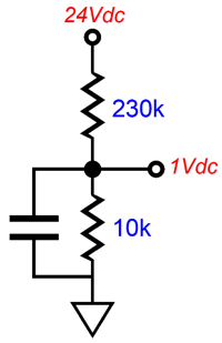
How do we get the 1V reference voltage?
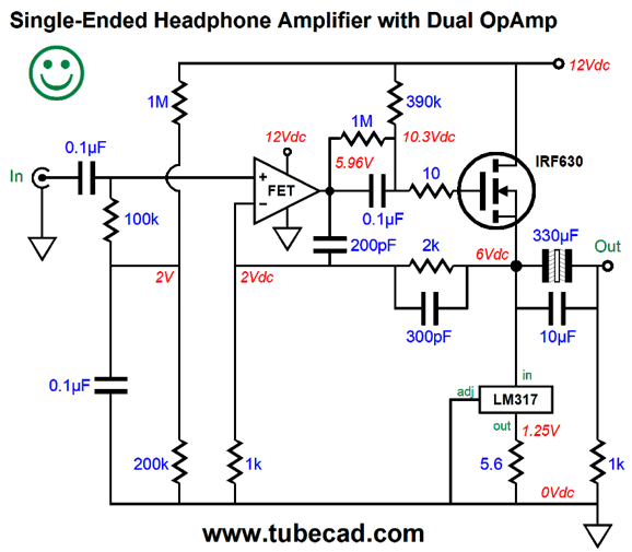
Switcher power supplies offer fairly tight voltage regulation, usually 1% or better. All we have to is voltage divide 24Vdc down to 1Vdc and strip away the ripple. I would use a fairly large shunting capacitor, as it would impose a slow ramping up of the idle current. This might make the perfect computer-speaker amplifier. [Updated July 4th] I decided to model the above amplifier in SPICE, the 12V version. After much modifying, the optimal design looks like this.
Note the lowever valued gate-stopper resistor values and the addition of two phase compensation capacitors. I also modeled a simpler version that used an LM317-based constant-current source in place of the bottom OPA2107 and IRF630; it worked equally well.
The LM317 is far cheaper than the OPA2107. The 5.6-ohm resistor sets an idle current of 223mA, as 1.25V/5.6 = 0.223A.
Music Recommendation: Yo-Yo Ma and Friends
The Not Our First Goat Rodeo album could only have been conceived and executed in the United States, as it drips with American gusto, although an eclectic mix of musical influences, such as Appalachia, bluegrass (and a smidgen of blues), Celtic, Chinese, country, jazz, and classical musical traditions. If I had to sum it up as concisely as possible, I would called it bluegrass meets string quartet. Others might call it great musicians jamming. Truly, the album is unclassifiable. (For the airplane pilots out there, that's you Jim, do you know what the title, Not Our First Goat Rodeo, alludes to?) When giving it a listen, start with the second track, not the first. This album follows the jazz-album tradition of a steamroller first track, which I have never liked (it might have been the result of the LP's first track enjoying the most extend high-frequency response due to more vinyl passing under the needle than during the last track). Enjoy. //JRB
User Guides for GlassWare Software
For those of you who still have old computers running Windows XP (32-bit) or any other Windows 32-bit OS, I have setup the download availability of my old old standards: Tube CAD, SE Amp CAD, and Audio Gadgets. The downloads are at the GlassWare-Yahoo store and the price is only $9.95 for each program. http://glass-ware.stores.yahoo.net/adsoffromgla.html So many have asked that I had to do it. WARNING: THESE THREE PROGRAMS WILL NOT RUN UNDER VISTA 64-Bit or WINDOWS 7 & 8 or any other 64-bit OS. I do plan on remaking all of these programs into 64-bit versions, but it will be a huge ordeal, as programming requires vast chunks of noise-free time, something very rare with children running about. Ideally, I would love to come out with versions that run on iPads and Android-OS tablets.
//JRB
|
|
I know that some readers wish to avoid Patreon, so here is a PayPal button instead. Thanks. John Broskie Special Thanks to King Heiple
John Gives
Special Thanks to the Special 80
I am truly stunned and appreciative of their support. In addition I want to thank the following patrons:
All of your support makes a big difference. I would love to arrive at the point where creating my posts was my top priority of the day, not something that I have to steal time from other obligations to do. The more support I get, the higher up these posts move up in deserving attention. If you have been reading my posts, you know that my lifetime goal is reaching post number one thousand. I have 493 more to go. My second goal was to gather 1,000 patrons. Well, that no longer seems possible to me, so I will shoot for a mighty 100 instead. Thus, I have 20 patrons to go. Help me get there.
Only $12.95 TCJ My-Stock DB
Version 2 Improvements *User definable Download for www.glass-ware.com |
||


| www.tubecad.com Copyright © 1999-2020 GlassWare All Rights Reserved |