| John Broskie's Guide to Tube Circuit Analysis & Design |
25 March 2020 Post Number 496
Killing Time I shut off the water, but the heater kept leaking from its 40 gallon tank. Towels, lots of towels. Lots of wringing of towels and dumping water. Sadly, the utility room is where I stored many boxes filled with books and magazines. Normally, due to the furnace, this is the warmest and driest room in our house, but now the bottom boxes had melted and their soaked contents had to be thrown away. I didn't particularly mind losing The Absolute Sound and Stereophile magazines, but I did mourn losing many Audio Amateur and Speaker Builder magazines. Mercifully, my MJ Stereo Technic and Audiocraft magazines were safe. Monday afternoon, after I had moved hundreds of pounds of boxes up three floors and pushed all of the contents of my workroom to one side and located a new water heater and plumber, the new water heater was in place. Both my back and wallet ached. The only positive aspect was that the plumber was a super nice fellow and we got to talk audio. He readily acknowledged that tube-based amplifiers sounded better than solid-state amplifiers—up to about a decade ago, but he thought that surely new advances in class-D design had turned the tables. I wish they had. I then told him about the Schiit Aegir (the Continuity) amplifier that I listened to for about two weeks and which I loved. Everyone who heard it said the same thing: sweet sounding. Alas, he seemed to lose interest when I pointed out that it didn't put out hundreds of watts. (By the way, if you haven't seen the new Schiit Sol turntable, you should.) In other words, I never got to write all that I planned on writing. Interestingly enough, much like our old water heater, the stream of circuits kept flowing. Indeed, when I am distracted, they flow the most abundantly.
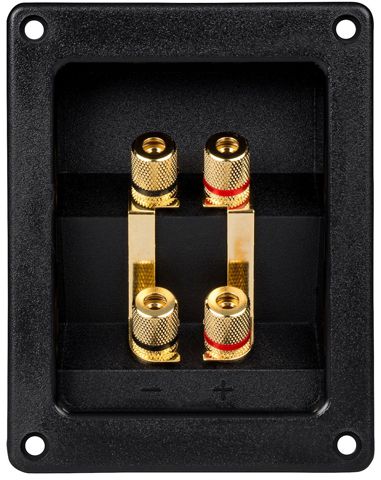
A Bi-Wire Answer I just performed a Google search with this query: "bi-wire site:tubecad.com" and 26 results came up. I hope the reader tried something like this. As I surveyed the Google Image results, I suspected that in spite of all that I had written on the topic, I might have left some territory uncharted. For example, we can force an active bi-ampping setup on the loudspeaker in spite of the internal passive crossover.
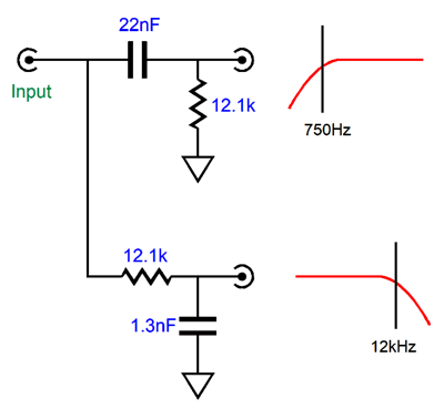
Let's say the speaker is a two-way design with a crossover frequency of 3kHz. We cannot put in place an additional 3kHz active crossover, as that would screw up the loudspeaker's frequency response. Here is an extreme example of why this would be a bad idea: the loudspeaker's crossover is 1st-order type and we place a 1st-order active crossover before the two power amplifiers. The result is that the speaker drivers now see a 2nd-order Linkwitz-Riley crossover, wherein each driver is down -6dB at the 3kHz crossover frequency. Sounds good, but it isn't, as the tweeter's phase must be flipped or a huge suck-out will center at the crossover frequency. In this example, we could flip the phase of the wires attaching to the tweeter's bi-wire terminals, but with any other crossover arrangement, the simple workaround wouldn't work. Let's say that the two-way crossover was a 3rd-order type, which are common in two-way loudspeakers. We could feed the woofer amplifier a 12kHz low-pass 1st-order filter and the tweeter amplifier a 750Hz high-pass 1st-order filter, as each filter is two octaves away from the 3kHz crossover frequency.
The assumption behind this circuit shown above is that the power amplifier input impedance is 47k, as this resistance must be included in the filter calculations. The tweeter amplifier certainly benefits more from this setup, as most of the musical content lies below 750Hz, which spectrographs of album's content reveal. But this unfair distribution is fine, as we can more readily hear clipping from tweeters than from woofers. Ideally, in this setup, the tweeter amplifier will never clip, while the woofer amplifier probably will often; yet, our ears will hear clean output. The obvious workaround is to use a much higher-output woofer amplifier. Additionally, if we were willing to open the loudspeaker, which actually means removing the woofer, we would probably find a two-resistor padding network attached to the tweeter, as most tweeters offer higher SPL with 1W of input than do most woofers. Since we could adjust the output level of the tweeter amplifier, we could remove the padding resistors, which would effectively make the tweeter amplifier much more powerful. For example, if the padding network imposed a -6dB attenuation, then a 16W tube-based tweeter amplifier would effectively become a 64W amplifier as far as the tweeter and our ears were concerned. Okay, perhaps I have mentioned all this before, but it's worth repeating. What I may not have mentioned before is that we could build a special tube-based tweeter power amplifier that took advantage of the limited bandwidth (750Hz and up). Low-frequency bandwidth and output transformer size are related. The lower the frequency that must be passed, the bigger the output transformer must be.
Let's say you desire a modest power bandwidth of 20Hz to 30kHz at 25W from a stereo tube power amplifier. Well, if the output transformers are not vastly larger than the power transformer, something went wrong, as 25W at 20Hz requires a much bigger transformer core than does 100W at 60Hz. What this means is that we can use a much smaller output transformer when we limit the low-frequency bandwidth to 750Hz. For example, we might use a Dynaco ST-70 output transformer (A470) with four KT88 output tubes, which could easily deliver over 100W at 750Hz and above—in spite of the output transformer's nominal 35W rating.
One danger, however, is heat. The idle current through the transformer would at least double, so the heat dissipated by the primary DCR would at least quadruple, as W = I²R. The workaround would be to air-cool the output transformers by providing perforated chassis holes around the transformers and maybe to place the transformer atop quarter-inch spacers, so air could flow across the bottom of the transformers. In addition, we ensure that greater distance separates the output tubes and power transformer from the output transformers. Worst-case, we could glue heat sinks to the transformer bell casing caps or fan cool the transformers. By the way, a friend of mine purposely uses smaller output transformers, say two KT88 output tubes with a 25W output transformer. Why? He states that he preferred the sound of transformer clipping to tube clipping. Beyond the use of smaller output transformers, we could get away with smaller-valued coupling capacitors with the tweeter amplifier. Indeed, with feedback-free output stages, the 750Hz low-pass filter could be achieved with the coupling capacitors to the output tube (or tubes, in a push-pull amplifier). For example, with a grid resistor of 300k, a 700pF capacitor would be needed. Or, differently arranged, we could use 1nF (0.001µF) coupling capacitor and 213k grid resistors.
Active Phono Equalization Later, I got ambitious and I built an elaborate tube phono preamp based on a Brian Clark design, which included a high-voltage regulated power supply. Other than being quieter, it did not beat the simple SRPP preamp, not in imaging or in ease of presentation. This troubled me. I then built what was effectively a Tetra phono stage based on 12AT7 tubes and it beat the SRPP preamp.
Since I was still convinced that all good-sounding amplifiers had to use negative feedback, I tried to make a better-sounding active equalization phono preamp; in vain. Passive always beat active. Why? Here is what I wrote back in 2002.
The above assumes an open-loop bandwidth far beyond 20kHz, which is certainly possible with discrete transistor or tube designs, but not with OpAmps. As I mentioned in a previous post, OpAmps offer insanely high open-loop gain, but severely truncated open-loop high-frequency bandwidth.
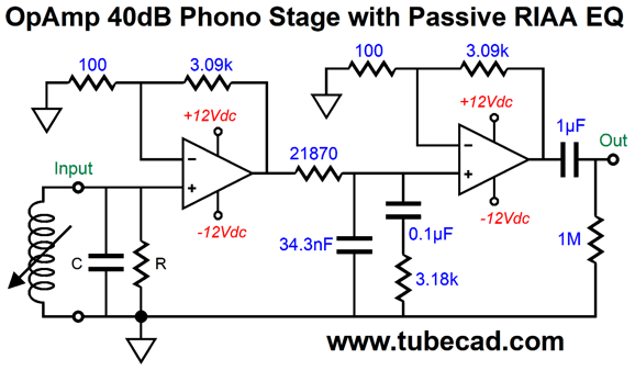
In other words, the OpAmp phono preamp might have an open-loop gain of 120dB, but a high-frequency roll-off between 1Hz to 50Hz. So the OpAmp-based 40dB phono preamp with active RIAA equalization would exhibit 60dB of negative feedback at 20-Hz but about 40 dB of feedback at 20-kHz. The question I asked myself was, What would a phono preamp with active equalization and constant negative feedback sound like? Here is an example of a two-gain-stage preamp with passive equalization.
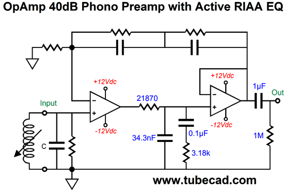
Each OpAmp provides 30dB of gain, seemingly making a total gain of 60dB; but as we lose 20dB due to the insertion loss of the passive equalization network, the final gain is 40dB. Now, what if we used both passive and active equalization?
The input amplifier's negative feedback loop encompasses the output buffer's output. The open frequency response looks just like the closed-loop response, but with more gain. The result would be constant negative feedback ratio across the audio frequencies, assuming a wide bandwidth input amplifier and output buffer. Here is the tube-based design I came up with 40 years ago.
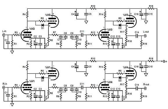
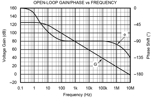
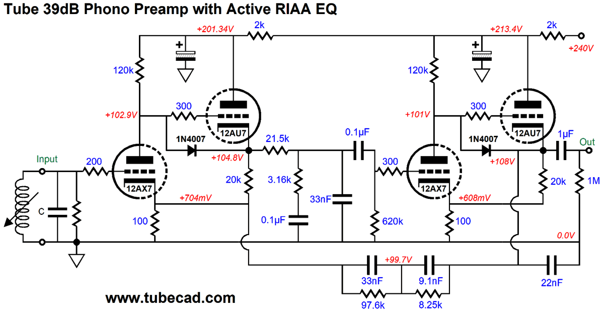
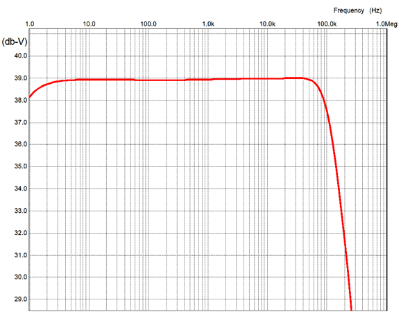
Two 12DW7/ECC832 tubes are used per channel, which are twin dissimilar-triode types, as each 12DW7 holds a 12AX7 triode and 12AU7 triode. The open-loop gain is 57dB; the closed-loop gain, 39dB. It took a lot of fiddling about in SPICE with the negative feedback part values to get a flat frequency response, which explains why my attempts to make a working version forty years ago failed. Sadly, the Tetra PCBs cannot be used to build this design, as the pin-outs on half the tube sockets would not work with the 12DW7 tubes. On the other hand, making a prototype on a perf board would be fairly easy, if a bit messy. By the way, both gain stages use a hint of positive feedback to boost the open-loop gain. With "all before us lie deserts of vast" time, this might prove an interesting project to undertake. Here is the SPICE-generated graph of the frequency response without the 2nd-order 50kHz low-pass filter imposed by record cutting-head's high-frequency bandwidth limitation.
Not too bad. The output is within 0.5dB from 20Hz to 20kHz. The addition of the 22nF capacitor shunting the output was needed to quell a resonance at 300kHz. The high-frequency cut-off slope may look steep, but it is only 6dB per octave, 20dB per decade.
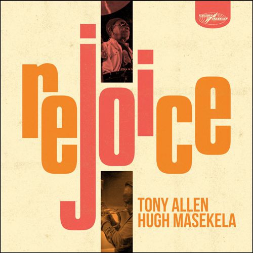
Music Recommendation: Rejoice, by Tony Allen, Hugh Masekela When I first saw the cover, I thought it must be a Blue Note or Atlantic reissue. It's not. The recording was started ten years ago and only recently completed. The Tidal offering is in MQA, which should unfold into 96kHz and 24-bit.
//JRB
User Guides for GlassWare Software
For those of you who still have old computers running Windows XP (32-bit) or any other Windows 32-bit OS, I have setup the download availability of my old old standards: Tube CAD, SE Amp CAD, and Audio Gadgets. The downloads are at the GlassWare-Yahoo store and the price is only $9.95 for each program. http://glass-ware.stores.yahoo.net/adsoffromgla.html So many have asked that I had to do it. WARNING: THESE THREE PROGRAMS WILL NOT RUN UNDER VISTA 64-Bit or WINDOWS 7 & 8 or any other 64-bit OS. I do plan on remaking all of these programs into 64-bit versions, but it will be a huge ordeal, as programming requires vast chunks of noise-free time, something very rare with children running about. Ideally, I would love to come out with versions that run on iPads and Android-OS tablets.
|
I know that some readers wish to avoid Patreon, so here is a PayPal button instead. Thanks. John Broskie
John Gives
Special Thanks to the Special 84
I am truly stunned and appreciative of their support. In addition I want to thank the following patrons:
All of your support makes a big difference. I would love to arrive at the point where creating my posts was my top priority of the day, not something that I have to steal time from other obligations to do. The more support I get, the higher up these posts move up in deserving attention.
If you have been reading my posts, you know that my lifetime goal is reaching post number one thousand. I have 504 more to go. My second goal was to gather 1,000 patrons. Well, that no longer seems possible to me, so I will shoot for a mighty 100 instead. Thus, I have 16 patrons to go. Help me get there.
Support the Tube CAD Journal & get an extremely powerful push-pull tube-amplifier simulator for TCJ Push-Pull Calculator
TCJ PPC Version 2 Improvements Rebuilt simulation engine *User definable
Download or CD ROM For more information, please visit our Web site : To purchase, please visit our Yahoo Store: |
|||


| www.tubecad.com Copyright © 1999-2020 GlassWare All Rights Reserved |