| John Broskie's Guide to Tube Circuit Analysis & Design |
16 September 2019 Post 477
RMAF 2019
When I learned of the upcoming change in venue at the last RMAF, I was pleased. Hell, I was more than pleased, as I was closer to overjoyed—although the old venue had recently gotten a facelift, it was still quite long in the tooth and seemed incapable of having both of its elevators working at the same time. In addition, the new location was slightly closer to my home. Be careful what you wish for, however, as you might get your wish good and hard. Well, we got it good and hard—all of us, the exhibitors and the attendees. The Gaylord Rockies Resort, a ridiculously mammoth of a hotel, swallowed up the RMAF as it were a dainty appetizer. The enormous structure could have contained ten RMAFs. Sadly, bigger isn't always better. Dwarfed by the immense hotel, the RMAF seemed tiny and insignificant. But do not imagine that the RMFA was comfortably tucked away in a corner. No, instead the RMAF was scattered about the hotel, so getting together with friends often required walking across football fields of distance. (The hotel is stupidly big. One exhibitor told me that early in the morning he went out to his car—unfortunately, without his hotel key, so he had walk around massive edifice until he found someone who would let him back in. Once inside, he looked at his Fit Bit and saw that he had already attained his daily goal of steps.) Worse, the RMAF was poorly signed, as only one sign greeted you after you exited the elevator on each floor, detailing who was showing in which rooms on that floor. But as the distance between exhibiting rooms was so great and the many hallways so long, we often gave up before arriving at the last audio-filled room and we often needlessly pursued long hallways to their empty ends. A poignantly pointless waste of time and effort. A few extra signs would have made a world of difference, with such handy notes such as "No More RMAF Exhibitors Beyond This Point" or "One more Exhibitor in Room 41,934."
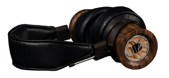
The bigger problem was the huge increase in room rates. Not one exhibitor told me that the new room rates were less than twice as expensive as years past and most said that they were easily three times the usual cost. The result was that only the few big boys or those with very deep pockets could afford to show up, which is tragic, as it's the small, new, wacky audio companies that offer the most interesting rooms. The headphone portion of the RMAF was also tiny, in spite of the much lower cost of renting a table in a ballroom. Well, no doubt some are thinking that the higher room fees must be offset by having larger, more nicely appointed rooms. Think again. The rooms were no larger and no nicer than those of previous RMAFs. In fact, an odd paradox obtained, wherein the doors worked supremely well at trapping noise inside the rooms, but the rooms all seemed nosier in general, perhaps due to the how the air conditioning was implemented, wall instead of window installations. In the headphone room, I could not evaluate headphones due to the high ambient noise. This was a dang shame, as I dearly wanted wanted to give the new Swan Song Audio headphones a serious listen.
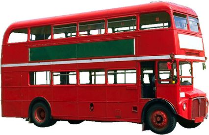
The baskets are made from walnut wood and unlike just about every other high-end headphone, they are sonically adjustable, as different types of wood disks can be interchanged, resulting in a different sonic signature. I can easily imagine that each music genre of music would find its preferred disk. To be honest, I am stunned that more headphones are not sonically adjustable. For example, take any preexisting open-back headphone and imagine if it was supplied with two form-fitting sealing caps, possibly lined with felt, which would convert the headphones to closed-back types. Why? At home, we would leave the sealing caps off; at a Starbucks, we might put the caps on to avoid hear the lamentations of the people sitting next to you. Many of the exhibitors told me that they were pleased with the crowds in their rooms, which helped take some of the sting off the increased cost of the room. But if 25% fewer attendees showed up and if half the exhibitors showed, the few remaining rooms would fill with people. A form of survivor bias, in other words. A less tragic problem, but a problem nonetheless, was that the Gaylord Rockies Resort is in the middle nowhere, with the Denver International Airport the only close by feature. In other words, once you are in the hotel you are stuck in the hotel. In contrast, the Marriott Tech Center in Denver was in Denver and you could walk across the street to bars and restaurants. In other words, this RMAF told me nothing about the state of audio in 2019, which is a shame. I used the RMAF as a proxy for high-end audio's general health and future. In short, if it weren't for my seeing old friends, I would have been happy to skip this year's RMAF. Perhaps, no RMAF could ever prove ideal, as too much works against it. It is hard enough to get good sound in our listening room; in a tiny hotel room, it's impossible. Back in post 309, I described a dreamlike alternative, wherein the show is held not in a hotel, but in a new housing development. Read post 309 and imagine boarding the buss to nirvana.
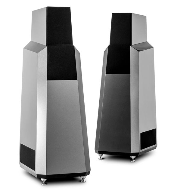
This year's highlight was the same as all the previous RMAF highlight: friends. It's great to see old friends and make new friends. I just loved talking with Richard Vandersteen, but then I always love talking to him. He is an American original and chockfull of audio insights. I would love to travel on a long cruise with him, as Richard is a walking audio encyclopedia and a wellspring of limitless great stories.
By the way, his Model 7 loudspeakers sounded fabulous, but then they always do. A spinning LP summoned Stravinsky and the speakers filled the room with sound, glorious and majestic. Symphonic works and those filled with massed voices are the hardest to reproduce, which explains why they are so seldom played at audio shows.
Low-Voltage Tube Phono Stage
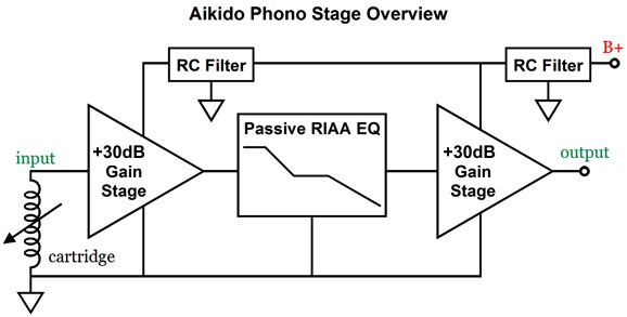
What about a phono preamp? If the circuit is solid-state, we would have no problem, as we could easily add a DC linear regulator to the switcher output. But what about a tube-based phono stage? Ideally, we would use two tube-based gain stages, each with a gain of +30dB, with a passive RIAA equalization in between gain stages, which would incur a -20dB insertion loss, bringing the total to 40dB of gain.
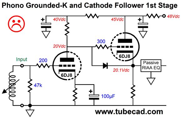
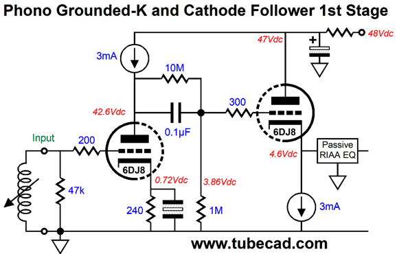
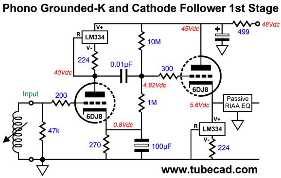
The big problem is that 48V is not a lot of B+ voltage. Even low-rp triodes, such as the 6DJ8 and 5687 and ECC99 require more cathode-to-plate voltage to perform best. Alas, no one is making modern production 6GM8/ 6N27P/ECC86 low-voltage dual-triode tubes and NOS versions now cost a fortune and the existing stock has already been picked over. This leaves us with the 6DJ8 as the only real candidate, as it combines a low rp (below 3k) with a fairly high amplification factor (mu) of 33. Still, we cannot do the following: The 6DJ8 needs a greater cathode-to-plate voltage and larger plate resistor value, if we are going to get enough gain and climb out of the non-linear bottom of its plate curves. One workaround is to use constant-current sources, which will yield a gain close to the triode's mu and shield the input stage from the B+ ripple.
(The odd looking capacitor symbol refers to anon-polarized electrolytic capacitor.) Both the input grounded-cathode amplifier and the cathode follower get the constant-current source treatment. The internal coupling capacitor is needed to give the cathode follower stage more voltage headroom. Now, it's super easy to just draw a constant-current source symbol, but much harder to actually implement a real one. If we could source high-voltage N-channel or P-channel FETs, these might prove ideal. In their place we can use an IC constant-current source, such as the LM334.
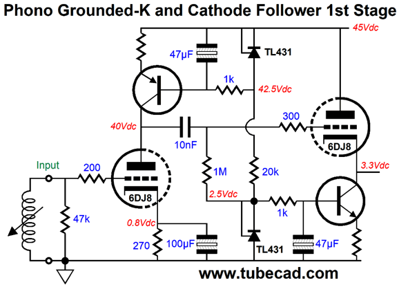
The LM334 is only rated for 40V, so the safe solution might be to place a 25V zener in parallel with it. Another constant-current source setup would use bipolar transistors.
Here the two LM431/TL431 shunt regulator ICs are configured as 2.5V voltage references that feed the transistor bases. I would use MJE15032 and MJE15033 transistors, as these TO-220 packaged transistors would dissipate so little heat that no heatsink would be required. We can get much fancier, however, as we could use an OpAmp-based constant-current source.
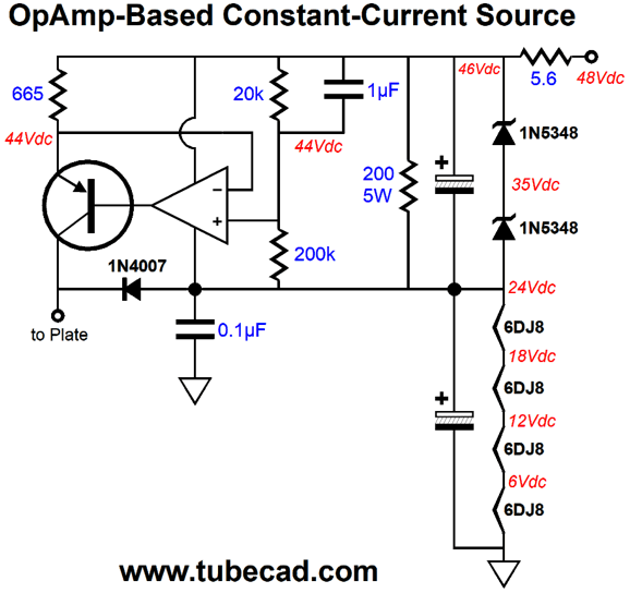
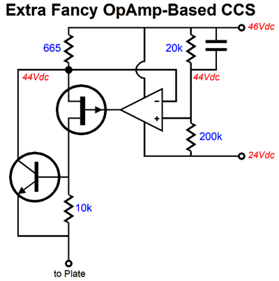
Here we see the 48Vdc from the switcher power supply working into an RC filter, which is formed by the 5.6-ohm resistor and the two electrolytic capacitors in series. This pre-filter removes much of the hash from the switcher power supply. The OpAmp should hold an FET input stage and offer low noise. The PNP transistor could be a low-voltage type, such as 2N4403, which is only rated for 40V, but the 1N4407 diode effectively limits the maximum emitter-to-collector voltage the transistor can see to 22.7 volts. Note that the 1µF film capacitor terminates into the OpAmp's B+ voltage, not ground. The 665-ohm emitter resistor sets the constant-current source current draw to 3mA. The 200-ohm power resistor is there to unload the two 11V Zener diodes. Note how the four 6-volt heater elements are wired in series. What about the second stage, the cathode follower, where does it connect? We could attach it to the 46V OpAmp B+ voltage or we could give it a voltage regulated B+ voltage.
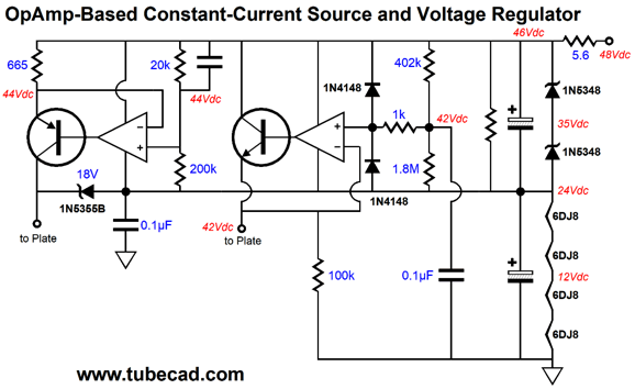
Imagine a unity-gain, low-noise dual or quad OpAmp being used. The NPN transistor functions as the pass device in the regulator. The 42V DC reference voltage is formed by the 402k and 1.8M two-resistor voltage divider and shunted by the 0.1µF capacitor to ground. The 100k resistor is there only to provide a current path at startup, while the triode is cold and not conducting. The 1N4007 diode was replaced by an 18V Zener for the same reason; we want the constant-current source portion to still draw current when the input triode is cold. By the way, if we want to get extra, extra fancy, we can use a P-channel FET and NPN transistor.
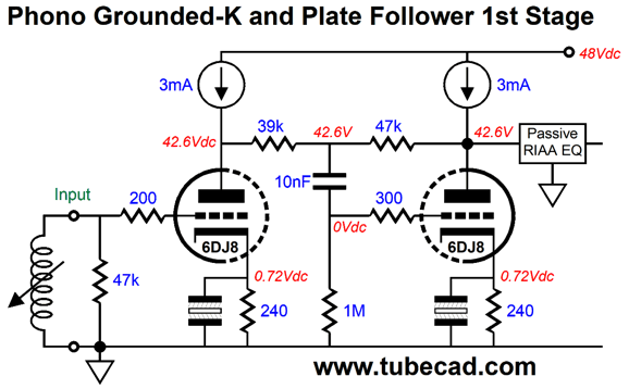
The FET's gate is like a triode's grid in that it presents a near infinite input impedance, unlike a transistor's base, which presents a relatively low impedance and draw current. In this fancy setup, the OpAMp controls the FET, which in turn controls the NPN transistor. Another possible tube circuit topology is a cascade of grounded-cathode amplifier into an anode-follower circuit.
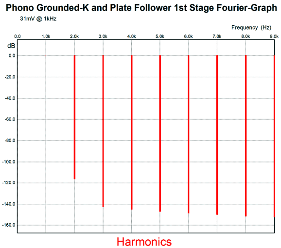
As configured, the gain is 31 (+30dB), which is partially set by the 39k and 47k inverting-amplifier feedback resistors. We could easily increase the total gain to +40dB for both gain stages, which would yield a final gain of 60dB. It's a bit risky, as the noise will probably prove excessive. (All my friends who have tried high-gain phono stages, as in 60dB types, have reverted to step-up transformers and 40dB phono stages.) Still it's great to have the flexibility of adjusting the gain both up or down as needed. Note how the two inverting stages result in no phase inversion. Also note how the two constant-current sources shield the triodes from the B+ voltage ripple. As the following graph show, the distortion is amazingly low.
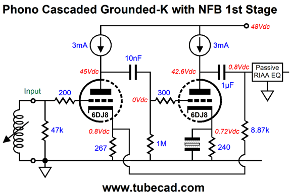
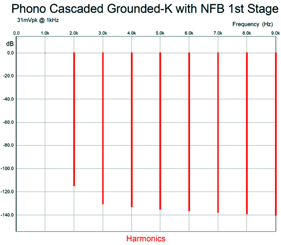
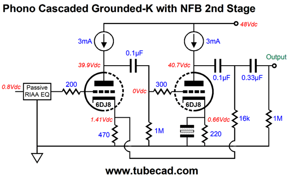
We can, moreover, use the two plate constant-current sources with a different topology, the two-stage negative feedback pair.
Both triode function as grounded-cathode amplifiers. No phase inversion results at the output, as the cascade of two inverted stages returns the phase to non-inverted. The output from the 6DJ8 on the right is returned to the input triode's cathode through the 8.2k negative feedback resistor. The distortion is low, which you can see from the graph shown below.
This arrangement sets the gain to 30dB and results in a 0.8Vdc DC offset, which will pass through the passive RIAA equalization network to the second gain stage, which can be compensated with a larger cathode resistor on the second stage, say a 470-ohm resistor.
Note the two coupling capacitors in series, which makes a total of five coupling capacitors throughout the entire phono stage.
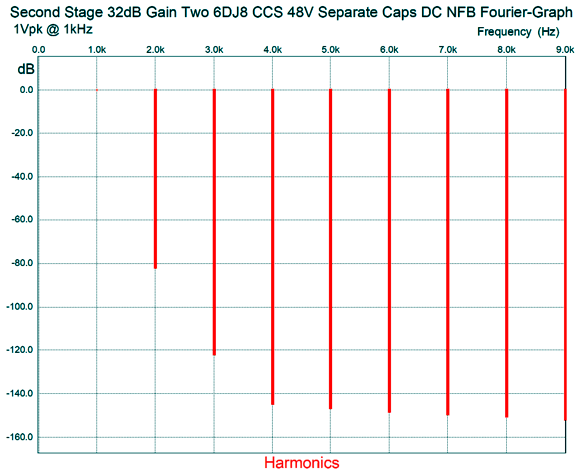
Alternatively, we can use this variation, which also uses five coupling capacitors altogether, but only one at the output.
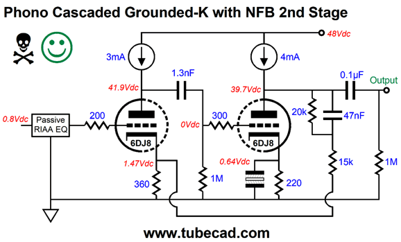
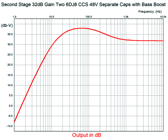
Why the skull and crossed bones? (If I were providing chess notation, I would have used !?) If we are not careful with the internal coupling capacitor values, we can get a huge bass boost, as in +24dB. Okay, why the happy face? If we are careful with the internal coupling capacitor values, we can purposely get a bit of a bass boost, as in +6dB at 60Hz, with a sharp cutoff below. Here is the frequency plot for the circuit shown above.
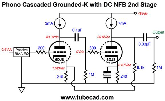
For some systems and certain tastes, this bass bump might lend the needed low-end heft and still avoid the problem of warped records. In other words, not for newbies. Another approach is the DC version, wherein we connect the negative feedback resistor directly to the second triode's plate, with an increased constant-current source current draw to compensate.
I was frightened by the look of this setup, as I feared that small discrepancies in the expected input DC offset voltage (0.8V) would cause huge DC voltage shifts. Well, in SPICE simulations, that scary outcome didn't arise. Still, if I had to choose, I would go with the two coupling capacitors in series version. Well, I went searching through my computer folders for low-voltage tube circuits. In a folder titled, 48V Phono Stages, I found the following circuit that I come up with long ago.
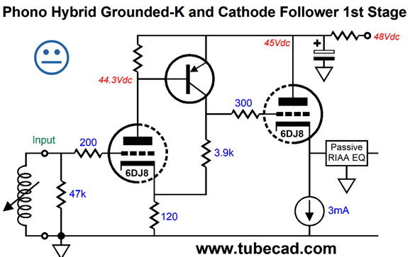
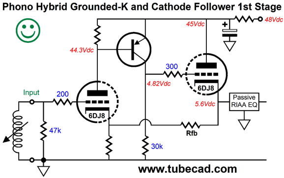
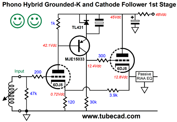
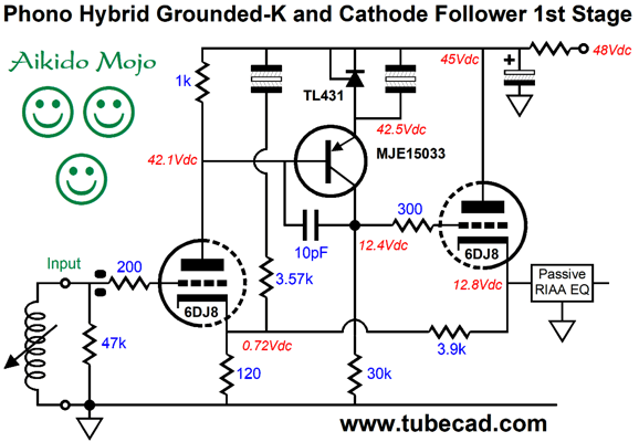
First of all, note that the input triode sees 44.3Vdc on its plate, which is healthy enough to get some good performance. Next, note that PNP transistor completes a negative feedback loop with the triode and the 120-ohm cathode resistor and the 3.9k collector resistor set the gain of this compound stage. The cathode follower Dc couples to the hybrid compound stage and offers a low output impedance. The only big problem is that the cathode follower with constant-current source loading delivers a relatively poor PSRR, as 1/mu of the B+ voltage ripple will appear at its output. Thus, the neutral face. In other words, if the B+ voltage is well filtered or regulated, then this circuit might work well enough, even for phono preamp use. On the other hand, if we enclose the cathode follower's output within the negative feedback loop, we can substantially reduce both is output impedance and noise contribution.
The PNP transistor now works into a 30k collector resistor, which allows the transistor to develop much greater open-loop gain. (The 30k value was chosen from SPICE simulation that showed it resulting in the lowest transistor noise.) The next step is to increase the gain delivered by the input triode.
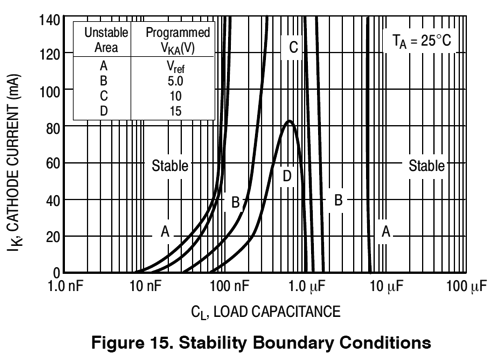
We added a 2.5V voltage reference made up from a TL431 shunt regulator IC. The 1k plate resistor allows the plate triode to control better the PNP transistor. When bypassing a TL431 with a capacitor, we need to consult the TL431's data-sheet, as a certain band of capacitor values will cause oscillations.
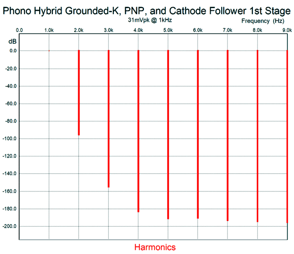
The distortion is quite low for this design, as shown in the SPICE-generated graph below.
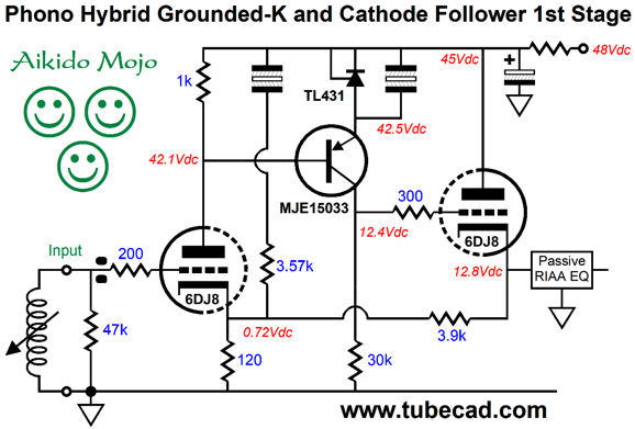
Mercy, mercy, mercy. The THD comes in at below 0.01%. Also note the lovely single-ended cascade of harmonics. This circuit's only real failing is that it offers almost no PSRR. In other words, whatever amount of power-supply noise taht exists at the B+ will also appear at the output. Major bummer. What is needed is some Aikido mojo. Fortunately, adding Aikido mojo comes as easily to me as swearing does to a standup comic.
This is the circuit I had created long ago and then forgot. In SPICE simulations, the PSRR came in at -46dB, which is a huge improvement over 0dB. (If we replace the 3.57k resistor with a 3.3k resistor in series with a 500-ohm potentiometer, we could trim for an even better PSRR figure.) The unmarked non-polarized electrolytic capacitors were 300µF types in my simulations. The MJE15033 made a big difference in reducing distortion and other PNP transistors might offer even better performance. Only one component is missing from this circuit: a 10pF capacitor to ensure high-frequency stability.
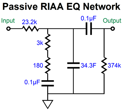
With the added capacitor in place, the high-frequency bandwidth extends to 260kHz. If RFI is an issue where you live, then we can replace the 10pF capacitor with a 100pF capacitor and reduce the high-frequency cutoff frequency to 110kHz. By the way, the two black rounded squares at the input represent a ferrite bead. Speaking of frequency, I haven't shown the passive RIAA equalization network that would mate with this first stage of amplification.
The amplifier circuit delivers an output impedance of about 5 ohms, so this resistance was included in the calculations. So, have I said all that I can say on the topic of a low-voltage phono preamp? Not likely. In fact, I am stunned by how all electronic topics seem limitless. For example, we didn't look into using an OpAmp-based first stage, followed by passive RIAA equalization network and ending with a tube-based circuit. Nor, did we look into using FETs with triode in cascode. In other words, given an infinite amount of time, time being the only variable I never have enough of, we could come up with an infinite number of possible circuits. Here is a quick example. The big problem we face is that 48Vdc is not a lot of B+ voltage. More would be better. Well, who says that we are restricted to using only one switcher power supply? Why not place two in series?
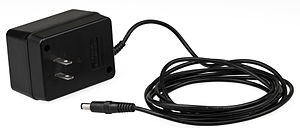
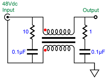
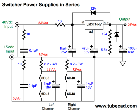
Here we see a 48V power supply stacked atop a 15V power supply, creating a raw B+ voltage of 63Vdc. We then use an RC filter to pre-filter the DC entering the LM317-HV regulator. Since this linear regulator is only rated for 57V, we protect it by using the two 12V Zener diodes in place of regular diodes. The 15V power supply powers the heater elements through 8.2-ohm power resistors. These resistors not only function as RC filters with the 1kµF capacitors, but also serve as current limiters, which will prevent the 15V switcher power supply from shutting down at startup and will increase the 6DJ8 life-span by limiting the current inrush when the heater elements are cold and present far lower resistance than when hot. Usually, switcher power connectors come in two prong sizes, 2.1mm and 2.5mm. We should use both with a setup that prevents plugging power supplies in the wrong power jacks. Indeed, it might be best to 48V switcher power supply with a four-pin DIN connector along with a 15V switcher with a 2.5mm prong, so no wrong connection would be possible. Another possibility would be to place two 48Vdc power supplies in series, which means that, once again, no wrong connection would be possible. Now, 96Vdc is a tube-happy B+ voltage and we could get away with using four 12AT7 or ECC99 tubes, placing the four heater elements in series and attaching the heater string across the bottom 48Vdc power supply. By the way, we could use this same 96V setup with an Aikido line-stage amplifier and four 12AU7 tubes.
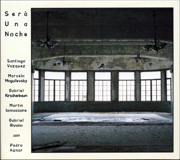
Music Recommendation: Será Una Noche The other album I picked up was by Puente Celeste, Nama, which made 2017 Stereophile's Records-to-Die For list.
Puente Celeste (Celestial Bridge in English) has a few albums showing up on Tidal.
Try the first album, En Vivo en Cafe Vinilo, and listen to the whole of track 3, Vals. It had my subwoofers working hard. As the single review at Amazon put it: "" //JRB
User Guides for GlassWare Software Since I am still getting e-mail asking how to buy these GlassWare software programs:
For those of you who still have old computers running Windows XP (32-bit) or any other Windows 32-bit OS, I have setup the download availability of my old old standards: Tube CAD, SE Amp CAD, and Audio Gadgets. The downloads are at the GlassWare-Yahoo store and the price is only $9.95 for each program. http://glass-ware.stores.yahoo.net/adsoffromgla.html So many have asked that I had to do it. WARNING: THESE THREE PROGRAMS WILL NOT RUN UNDER VISTA 64-Bit or WINDOWS 7 & 8 or any other 64-bit OS. One day, I do plan on remaking all of these programs into 64-bit versions, but it will be a huge ordeal, as programming requires vast chunks of noise-free time, something very rare with children running about. Ideally, I would love to come out with versions that run on iPads and Android-OS tablets.
|
Special Thanks to the Special 85!
I am truly stunned and appreciative of their support. In addition I want to thank the following patrons:
All of your support makes a big difference. I would love to arrive at the point where creating my posts was my top priority of the day, not something that I have to steal time from other obligations to do. The more support I get, the higher up these posts move up in deserving attention. Only those who have produced a technical white paper or written an article on electronics know just how much time and effort is required to produce one of my posts, as novel circuits must be created, SPICE simulations must be run, schematics must be drawn, and thousands of words must be written. If you have been reading my posts, you know that my lifetime goal is reaching post 1,000. I have 523 more to go. My second goal is to gather 1,000 patrons. I have 915 patrons to go.
The Tube CAD Journal's first companion program, TCJ Filter Design lets you design a filter or crossover (passive, OpAmp or tube) without having to check out thick textbooks from the library and without having to breakout the scientific calculator. This program's goal is to provide a quick and easy display not only of the frequency response, but also of the resistor and capacitor values for a passive and active filters and crossovers. TCJ Filter Design is easy to use, but not lightweight, holding over 60 different filter topologies and up to four filter alignments: While the program's main concern is active filters, solid-state and tube, it also does passive filters. In fact, it can be used to calculate passive crossovers for use with speakers by entering 8 ohms as the terminating resistance. Click on the image below to see the full screen capture.
Tube crossovers are a major part of this program; both buffered and un-buffered tube based filters along with mono-polar and bipolar power supply topologies are covered. Available on a CD-ROM and a downloadable version (4 Megabytes). |
||


| www.tubecad.com Copyright © 1999-2019 GlassWare All Rights Reserved |