| John Broskie's Guide to Tube Circuit Analysis & Design |
27 June 2019 Post Number 469
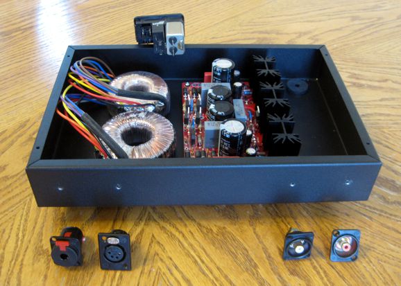
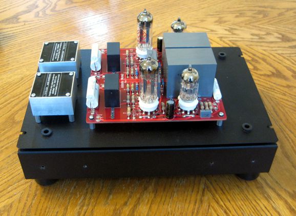
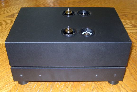
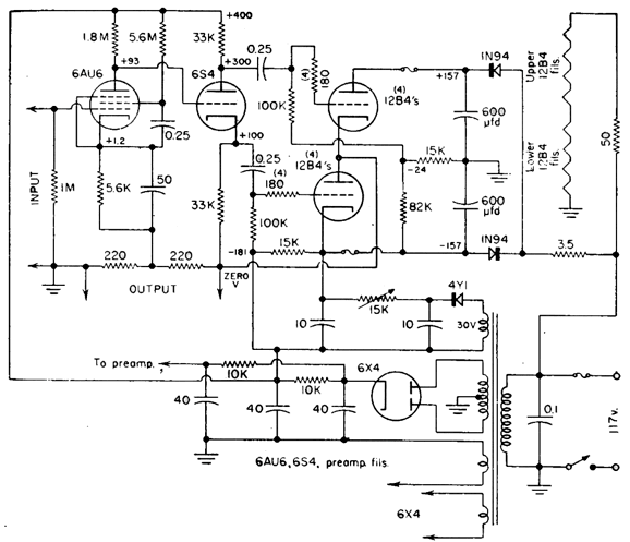
My Latest Project
I plan on plugging the interconnects right on the front panel and using the signal source's own internal volume control, so no potentiometer is needed. The top box rests on hollow Sorbothane isolators, through which wires will travel from the bottom box to the top box, such as B+, ground, input signals cables, and then cables from the transformers to the headphone jacks. In addition, the top box will hold a mode switch that will offer settings: inverted, muted, non-inverting.
The top box is a punched enclosure that functions as an amplifier cage. I plan on using magnet strips to hold it in place.
Sadly, I was in hurry to punch the holes in the top cage, so I didn't realize that my ultra-cheap Amazon hole punches didn't exactly match the screw treads of all my other super-expensive punches. The result was that the metal was deformed and I damaged my hydraulic hole punch stud. Damn. I will post more pictures as the project moves along. So why did I publish these photos? I want to finish this project, not let it sit un-built for years. Making it public makes it more of a strong commitment I am undertaking—besides, it might inspire others.
Solid-State Split-Load Phase Splitters in an OTL Amplifier
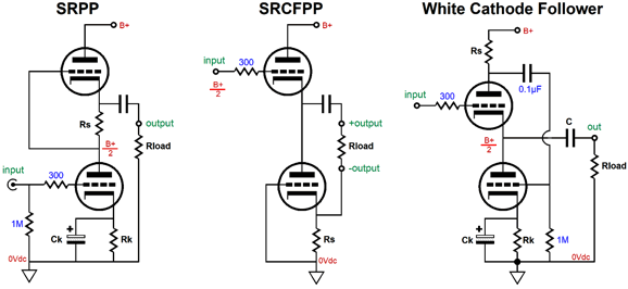
Many whose experience has been primarily with conventional transformer-coupled tube power amplifiers can never successfully transition over to OTL design, as an OTL output stage often bring problems unknown to those schooled in conventional transformer-coupled tube power amplifier design: choosing between cathode follower or grounded-cathode amplifier operation, ensuring equal output tube current swings, and dealing with PSRR issues. Think about it: 99.99% of conventional transformer-coupled tube power amplifier are grounded-cathode designs, where the load attaches to the plates; and these amplifiers do not have to worry about balanced current swings, as long as the phase splitter delivers a balanced output; and the same holds true for the issue of PSRR, as the output tubes will pretty much ignore common-mode signals, which most noises are. In contrast, in designing an OTL power amplifier, how we go about achieving equal, balanced, ideal anti-phase current swings can get tricky. In order to achieve ideal push-pull operation, we need two phases of input signal (the dictionary word for this is "diphasic," which is taking on a new meaning of two stages in succession, such as depression followed by elation). With a balanced input signal, consisting of a positive and negative and ground, we get a free set of anti-phase signals. With the typical unbalanced input signal, i.e. RCA jacks, we must create the needed anti-phase signal; usually, we use a phase splitter, but not always. The Trinity—or is Three Stooges closer to the mark—of lazy push-pull output stage topologies, the SRPP, SRCFPP, and White cathode follower, all use a single current-sense resistor to create the needed anti-phase signal for driving the opposing tube. In other words, even in these three lazy topologies we find an implicit phase splitter.
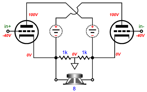
The transformer-coupled tube amplifier usually arrays the two output tubes horizontally, whereas the OTL arranges the output tubes vertically.
This practice is based on convention, not necessity, as we could flip the tube layout, using vertical tubes with an output transformer and horizontal tubes with an OTL, as the famous circlotron does.
The horizontal layouts differ radically from the vertical layouts in that the push-pull input signals are equal in magnitude; not so, with the vertical arrangement of output tubes.* In the vertical arrangement of output tubes, the top output tube must see much larger input signals than the bottom output tube, as the output is taken at the top tube's cathode, so its input signal must at least include the output voltage swing and whatever additional input signal is needed to bring about the output swing. In other words, the phase splitter must deliver an asymmetric set of anti-phase signals to the vertical arrangement of output tubes.
In addition, the phase splitter in the horizontal layouts differs in that is leaking of power-supply noise is largely nulled by the horizontal arrangement of the output tubes, as the leaked ripple prompts equal reactions from both output tubes, resulting in no net output signal for the secondary to relay to the loudspeaker.
Well, this is true at idle, as both output tubes are conducting. Once the output stage leaves its class-A window of operation, the single conducting tube will impose the ripple upon its output and the loudspeaker will react to it. I call this dynamically-induced poor PSRR, which I believe explains why many push-pull tube amplifiers take on a severe coarsening of the output at high volume levels. dynamically-induced poor PSRR probably explains why so many instantly prefer the sound from single-ended amplifiers, as whatever PSRR issues a single-ended amplifier suffers from, at least the noise is consistent. In the vertical layouts, however, dealing with PSRR issues is seldom contemplated, yet they can ruin an otherwise excellent design. Ideally, we want an OTL output stage to exhibit three design goals: equal anti-phase current swings from the output tubes, fine PSRR, and load Independence. The Trinity of lazy push-pull output stage topologies can only potentially deliver two of these goals, equal anti-phase current swings from the output tubes and a fine PSRR figure. All three are intrinsically load dependant. The job of getting an OTL output stage to exhibit these three design goals falls to the phase splitter. Back in post 232 , I showed a tiny OTL headphone amplifier that successfully met all three goals.
The assumption here was that the input stage would leak 50% of the power-supply noise to the phase splitter. Based on this assumption, the phase splitter was designed to create a ripple null at the amplifier's output. Understand, that this null only obtains while the output stage is working within the class-A window of operation, which means that neither output tube has turned off. Here is an analogy: imagine that during an arm wrestling match—a battle that is locked in a perfect draw—one of the contestants abruptly gets up to visit the men's room, thus eliminating the draw, as the remaining arm slams down on the table. The draw was only possible while the two were engaged in the struggle.
In other words, dynamically-induced poor PSRR is just as much a problem to be dealt with in an OTL amplifier as it is a conventional transformer-coupled tube amplifier. Ideally, the B+ voltage will prove rock solid and noise-free. Realistically, most power amplifier power supplies will at least sag under heavy output, if for no other reason that the power transformer's own primary and secondary DCR become a greater liability under high-power output. Yet another reason to love class-A operation. In post 232, I showed how an NPN transistor could replace the triode in the phase splitter.
The main advantage the transistor offers, other than being much cheaper and longer-lasting than the triode, is that it can work with far less voltage than the triode can, which will allow for larger output voltage swings. A transistor can work with only a few volts spanning from emitter to collector. Tubes are not so lucky. In fact, the split-load phase splitter presents a maximum voltage swing before the grid become positive relative to the cathode. Here is a longish quotation from post 167:
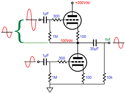
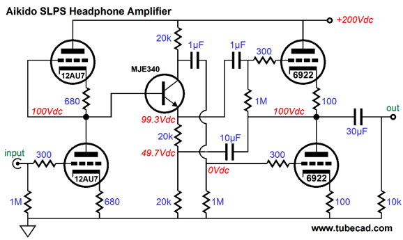
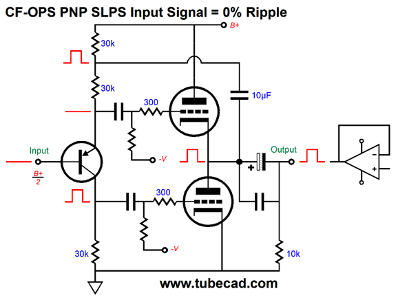
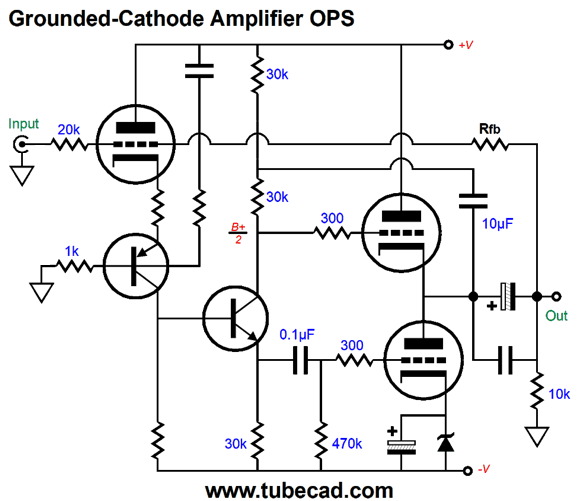
Usually, big output voltage swings are not needed in an OTL headphone amplifier, but they could certainly come in handy with a transformer-coupled tube headphone amplifier, even on that held its output tubes vertically in the totem-pole configuration. Well, the schematics from post 232 came up in a Google search, which instantly prompted my mind to envisage modifications and complete rearrangements. The first thought I had was: why can't a PNP transistor be used in place of the NPN type? Well, the big problem is that it simply won't work, as the DC voltages will all be wrong. The 100V voltage drop across the top 20k resistor implies a 200V voltage drop across the two 40k of resistance made up of the two bottom 20k resistors in series, making for a total voltage drop of 300V, which is —given the 200V B+ voltage— Impossible. The workaround is to add an additional internal coupling capacitor.
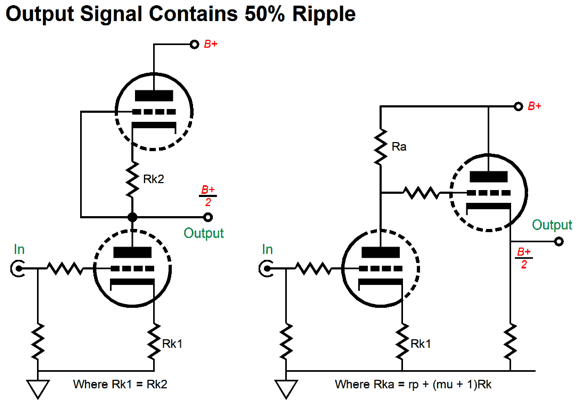
Now the top 20k resistor sees only 50V, so the combined resistance of 40k sees 100V. So are we good? Not quite, as the output stage no longer functions as a cathode follower, being now configured as a grounded-cathode amplifier. Okay, now is the time to downshift, as the following is a huge conceptual challenge for many, which I have discovered in one-on-one conversations. The basic triode amplifier topologies are grounded-cathode amplifier, cathode follower (aka grounded-plate amplifier), ground-grid amplifier, and grid amplifier (which few know exists, wherein the grid and plate swap functions). In OTL amplifiers, the only real choices are cathode follower and grounded-cathode amplifier topologies. (Why not grounded-grid? If you are going to drive a low-impedance cathode, then you might as well drive the external load directly.) Only one topology, cathode follower or grounded-cathode amplifier, should be used. Several OTL amplifier designers have tried to combine both in one output stage—with horrific results.
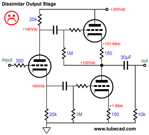
The top triode functions as cathode follower, so it delivers slightly less than unity-gain and a low output impedance; the bottom triode, in contrast, functions as a grounded-cathode amplifier, which does develop gain but also a high output impedance. This is a bad mix. Ideally, we want both triodes to offer the same gain and output impedance. You might be able to fiddle with the part values enough to get this blended output stage to work with one load impedance; but once the output stage leaves its class-A window of operation, the dissimilar output impedances will cause a big jump in distortion.
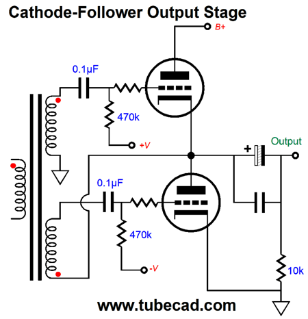
Which is better: cathode follower or grounded-cathode amplifier output stages? It depends. The cathode follower output stage will offer lower output impedance, but also lower gain. The grounded-cathode amplifier will deliver gain, but higher output impedance, which can be undone by a global negative feedback loop. The same global negative feedback loop, however, can be applied to the cathode follower output stage, but as the cathode follower offered no signal gain, the negative feedback has less open-loop gain to drive it. In other words, with a negative feedback loop in place, both topologies can work equally well. If no global negative feedback is used, then the cathode follower output stage is preferred. One exception might be in a headphone amplifier or an OTL amplifier that drives a relatively flat impedance, which most loudspeakers do not present, wherein the grounded-cathode amplifier configuration's higher output impedance would approximate a current-output amplifier. How high would the output impedance be? Roughly, the plate resistance divided by two. For example, an ECC99 presents an rp of about 2300 ohms, so the output impedance would be 1,150 ohms with two ECC99 triodes. In contrast, the same ECC99 used in a cathode follower output stage without a global negative feedback loop would present an output impedance of about 50 ohms. How do we configure a cathode follower output stage? The bottom tube must be connected to the output.
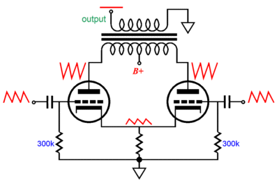
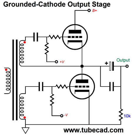
Both secondaries deliver the same amplitude of output signal. Note how the top triode functions as a cathode follower, as its input signal is ground referenced and its grid is fixed in place, so any attempt to move its cathode voltage either up or down will prompt large countering current swings. Also note how the bottom triode also functions as a cathode follower, as any attempt to move its plate voltage either up or down will prompt large countering current swings, as its grid sees 100% of the changes in plate voltage. This configuration will deliver slightly less than unity gain and a low output impedance. How do we turn this output stage into a grounded-cathode amplifier?
Now, the bottom triode's input signal is ground referenced, while the top triode sees its input signal referenced to the output, so it can deliver gain, but no cathode-follower-like low impedance. Any attempt to move its cathode voltage either up or down will no longer prompt large countering current swings, as its grid voltage will move with those voltage changes. The top triode is functioning like a grounded-cathode amplifier and it can only offer its plate resistance to oppose movements of its cathode voltage. Okay, how can we use the PNP-based phase splitter and restore cathode follower functioning? We need to move where the 10µF capacitor that connects to the output terminates.
Now, the both top and bottom triodes function as cathode followers. If the output is forced 1V more positive, that positive pulse will be relayed to the bottom triode's grid, so both triodes will react equally to the pulse. We cannot, however, just plug this circuit into the old headphone amplifier circuit, as the assumption here is that the phase splitter will see a perfectly clean input signal with no power-supply noise riding atop the input signal. In contrast, in the original design from 2012, the assumption was that the input signal will contain 50% of the power-supply noise. This means that this PNP-based version will pass on the power-supply noise just as if it were music signal. Not good.
Essentially, we face four likely possibilities: no power-supply noise, 50% of power-supply noise, all the noise, and some other portion of power-supply noise present on the phase splitter's input signal—and each percentage finds its own preferred topology. It may seem as it there are actually only two possibilities, no power-supply noise and some power-supply noise. The 50% and 100% cases are special, however, so they get their own treatment.
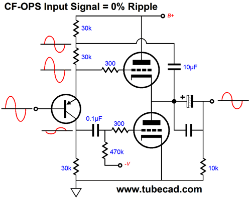
Input Signal Contains No Power-Supply Noise
The bottom tube "sees" the output through the 10µF capacitor and the middle 30k emitter resistor and the PNP transistor. How this works is that the MJE350 PNP transistor's emitter is not moving, as the transistor's base is not moving; thus, if we force the output positive, the 30k emitter resistor will see a greater voltage drop, which prompt a greater current conduction, which in turn will be relayed through the transistor, in phase, to its collector resistor, allowing the bottom tube's grid to move up positively, forcing the bottom triode's current flow to increase, pulling down the output voltage.
Note that both output tubes see the same amount of correction voltage, as the top tube sees its cathode go up by the same amount as the bottom tube sees its grid voltage go up. In other words, the top tube will decrease its current flow by the same amount that the bottom tube will increase its flow. This arrangement works well with a bipolar power supply and a ground-level input.
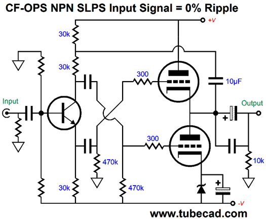
This circuit makes a fine load-independent power buffer, which could drive long interconnect, heavily laden with capacitance or fairly low impedance headphones. Since most tube-based line-stage amplifiers can easily swing big voltages, this circuit's less than unity gain should not prove to be a big problem. If truly low-impedance loads must be driven, say 32-ohm headphones, then we could place more output tubes in parallel. Using an NPN transistor in the phase splitter requires flipping the outputs from the phase splitter to the output tubes.
Note the additional shunting capacitor across the bottom 30k resistor. We can eliminate this big-valued capacitor by using an input coupling capacitor instead.
Of course, if the proceeding stage offered a low output voltage, we could DC couple the phase splitter to it. We can use this arrangement with a bipolar power supply.
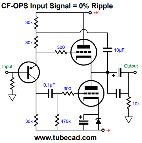
Note that the transistor's base voltage should sit between 0V and the negative power-supply rail voltage. It may look like we will encounter PSRR issues, but we don't, as the top output triode's grid sees no power-supply noise, while the bottom triode's grid sees 100% of the negative power-supply rail noise. Do not forget that just because the input signal is noise-free, the phase splitter and output tubes still have to deal with the power-supply noise.
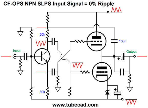
The negative power-supply rail's ripple gets relayed through the transistor to the top 30k resistor, so the bottom tube does not react to the ripple, as both its cathode and grid see the power-supply noise and the bottom triode offers only its plate resistance in opposition to the ripple, just as the top triode does to the ripple present on its B+ voltage. Assuming both power-supply rails share the same amplitude and anti-phase ripple, the result is a power-supply-noise null that the output. If we wish to run a grounded-cathode amplifier output stage instead, then stop crisscrossing the input signals from the phase splitter to the output tubes.
This arrangement should not be used with a bipolar power supply, as the only way we can prevent the negative power-supply rail noise from leaking into the output is to use an input signal that contains 100% of the negative power-supply rail noise, which is possible, as the following schematic shows.
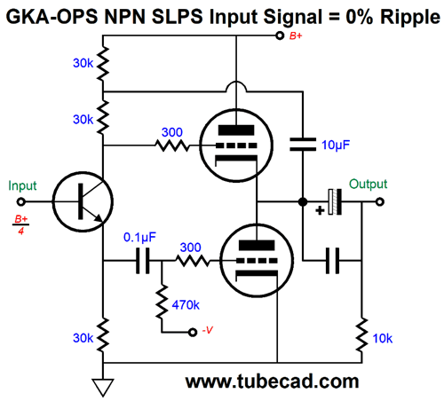
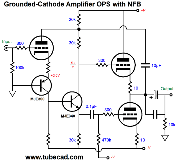
The input triode is configured as a cascode with the PNP transistor. The seemingly extra resistor that attaches to the PNP transistor's base and the seemingly extra capacitor that terminates at the B+ voltage are Aikido mojo parts that undo the input triode's reaction the positive power-supply rail ripple. This circuit can potentially develop a gob of gain, which could feed a global negative feedback loop. Note that the entire amplifier inverts the input signal's phase; thus, the negative feedback loop would be of the inverting amplifier type, wherein the feedback resistor would span the output to the input triode's grid.
If we add an input coupling capacitor, then we can attach the feedback resistor to the top output tube's cathode. Indeed, we could then replace the cascode's collector resistor with a constant-current source. In fact, we might be able to swap the NPN transistor out for a triode. We can get sneaky and use a hidden negative feedback loop, which few would spot.
The input triode becomes part of the global negative feedback loop. For example, if output is forced positively, the positive pulse will be relayed to the input triode's plate through the 10µF capacitor, causing the input triode to increase its current conduction, creating a positive pulse at the bottom output tube's grid, which will buck the positive pulse, as the bottom tube pulls down.
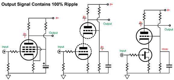
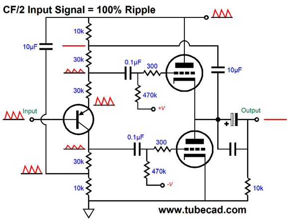
Input Signal Contains 100% Power-Supply Noise
The pentode's extremely high plate resistance makes a poor two-resistor voltage divider with the plate resistor and the same holds true for the cascode amplifier, particularly the one on the right, which places a triode atop a FET. If we use a PNP transistor in the split-load phase splitter, then the only solution I can think of is to halve the power-supply noise fed to the top output tube and inject 50% of the power-supply noise into the signal the bottom output tube sees at its grid. In other words, we will have to throw away some the input signal.
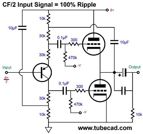
Okay, I admit this one looks daunting, so let's start slowly. The input signal containing 100% of the power-supply noise enters the transistor's base, which its emitter faithfully delivers to the two-resistor voltage divider made up of the top two 30k resistors. Thus, the top output tube sees 50% of the power-supply noise. How much of the input signal does it see? It depends. Imagine that the output is shorted to ground through the output coupling capacitors. In this case, 50% the input signal will be lost. Now imagine no external load impedance. In this case, the output will come close to unity-gain, so very little of the signal will be lost.
The bottom output tube sees 50% of the power-supply noise at its grid, as the extra 10µF capacitor on the left relays all of the power-supply noise to the bottom of the 30k collector resistor, which then appears at the top of the resistor minus the anti-phase current variation induced by the PNP transistor's emitter imposing the same power-supply noise onto the two-resistor voltage divider made up of the two top 30k resistors. Since 60k is twice 30k, the bottom 30k resistor experiences this varying current flow erasing half of the power-supply noise that the 10µF capacitor relayed. The bottom output tube's grid will also see an anti-phase audio signal equal to what the top output tube sees at its grid relative to its cathode. Assuming the dead short at the output and an input signal of +2Vpk, the top output tube will see +1Vpk and the bottom output tube will see -1Vpk. All 30k resistors are in the same current path, so all will experience the same voltage drops. If the top 30k resistor sees one volt less, then so, too, will the bottom 30k resistor. This topology makes for a half-cathode-follower operation, as we do not get the full cathode follower functioning, much like a circlotron output stage. In other words, the two-resistor voltage divider formed by the two 30k resistors in series halves the potential cathode follower reaction to external changes to the output voltage.
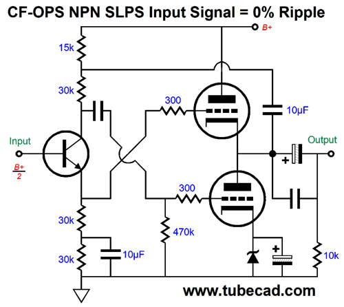
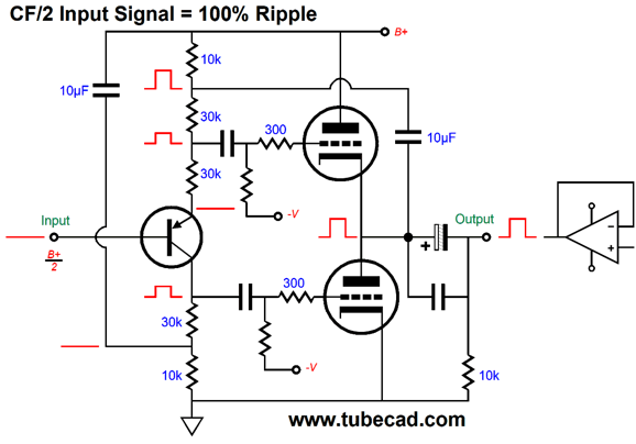
Imagine we used either a battery or a robust solid-state power amplifier to force the output positive by +2V. Note how the top of the two-resistor voltage divider string sees 100% of the positive pulse, but the top output tube's grid only sees a +1V pulse. Effectively the top output tube sees its cathode becoming 1V more positive than its grid, so its current conduction will only fall half as much as it would have with the full 2V differential that a true cathode follower would experience. Since the 2V pulse appears across the 60k load made up of the two-resistor voltage divider, the bottom 30k resistor sees a positive 1V pulse, as 2V/60k = 1V/30k. Both output tubes react equally, but out of phase with each other to the pulse. The top tube conducts less, while the bottom tube conducts more. The output impedance of this output stage is the same as a circlotron's output impedance when using triodes: rp/(mu + 2); with pentode output tubes, 1/gm. Here is an example of a complete OTL amplifier using the half-cathode-follower output stage and experiencing 100% power-supply noise entering the split-load phase splitter.
The pentode input stage offers almost no PSRR, but the output delivers a fine PSRR. The amplifier—as a whole inverts the input signal's phase—so the only negative feedback loop we can impose is the inverting-amplifier configuration that returns the feedback resistor to the pentode's grid. As for my trick of terminating the pentode's plate resistor into the connection between the top 10k resistor and the 10µF capacitor, this would only work if we switch to grounded-cathode output stage.
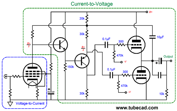
The phase splitter and output stage effectively become a current-to-voltage converter and the pentode effectively becomes a voltage-to-current converter.
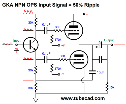
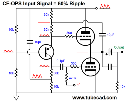
Input Signal Contains 50% Power-Supply Noise
Both the top and bottom output tubes see the same 50% of the power-supply noise in phase, so the output experiences a power-supply-noise null—as long as the two output tubes are both conducting. Since this circuit inverts the input signal's phase, we can return a negative feedback loop to the input tube's cathode.
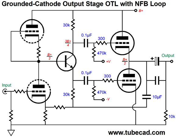
Note how the bottom 30k resistor has become two resistors that function as the negative feedback loop for the amplifier. If we wish to use a PNP transistor instead of the NPN type, we have to get dang clever. We retain the cathode follower output stage and create a power-supply noise null at the output by using two 10µF capacitors, one connecting to the output, the other to the B+ voltage.
The transistor's emitter relays the 50% of power-supply noise from the input stage to the top output tube's grid, but the top of the 30k emitter resistor sees no power-supply noise, so the induced current variation through this 30k resistor will be transmitted down into the bottom 30k collector resistor. Since the 50% of the power-supply noise is treated as signal by the PNP transistor, the signal gets inverted at its collector. The inverted power-supply noise meets the 100% of the power-supply noise relayed by the 10µF capacitor and results in 50% of in-phase power-supply noise presented to the bottom output tube's grid. Since both output tubes see the same amount of power-supply noise in phase, the output remains power-supply noise free. Dang sneaky, no?
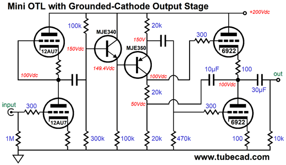
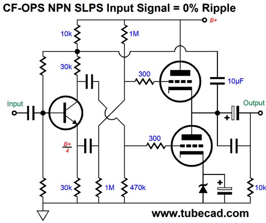
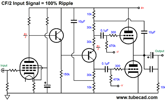
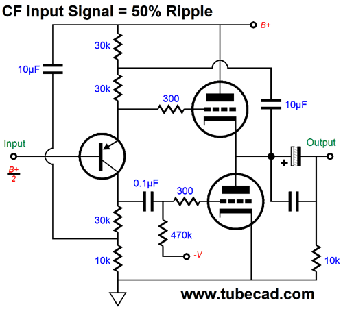
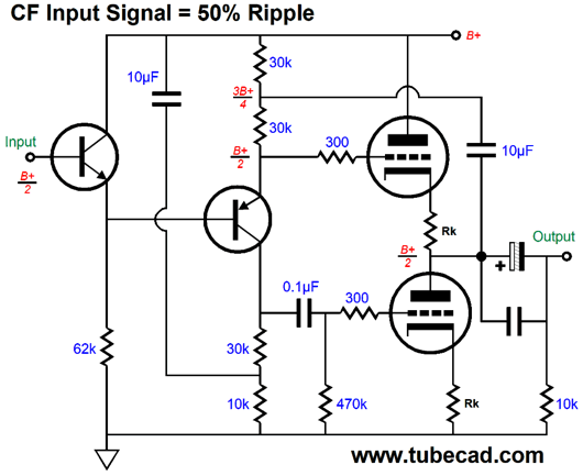
What about the actual audio signal we want to amplify? The phase splitter's connection to the output through the 10µF ensures that both output tubes get their required magnitude of input signal, regardless of the load impedance. We can lower the input impedance the input stage sees by adding an NPN transistor based emitter follower.
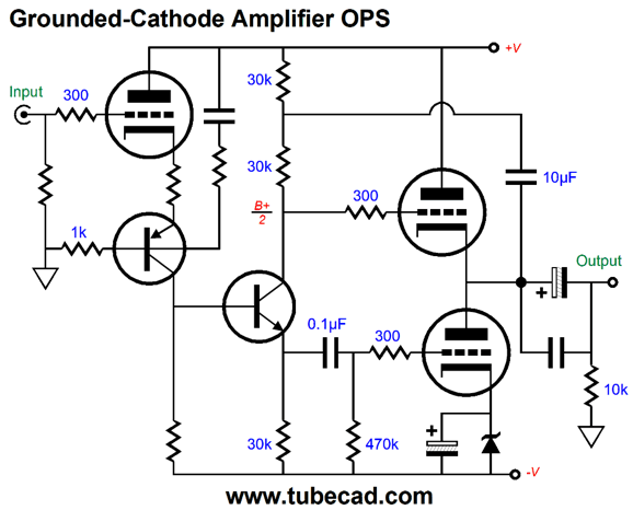
In addition, the cascade of transistors results in no DC shift from input to output. Putting it all together is easy enough.
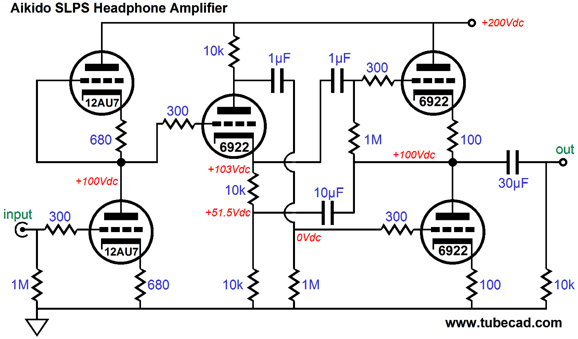
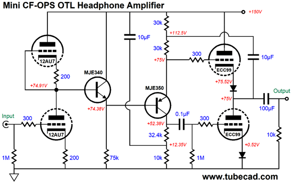
The 12AU7-based input stage delivers a gain equal to the 12AU7's amplification factor (17), so the phase splitter sees the 8.5 increase in the input signal and cathode follower output stage loses some of the gain driving the low-impedance load. The output stage uses diodes in place of cathode resistors to bias the output tubes, which ensures a lower output impedance. In short, this would make a fine mini OTL headphone amplifier for driving 150- to 600-ohm headphones. If lower impedance headphones are used, then we should place more ECC99 triodes in parallel, say three per channel for 32-ohm headphones. A total of eight tubes in a stereo headphone amplifier would look cool. I would travel to the parts department of an American car dealership, where I would search for a fine chrome-plated V8 medallion to adorn the face-plate.
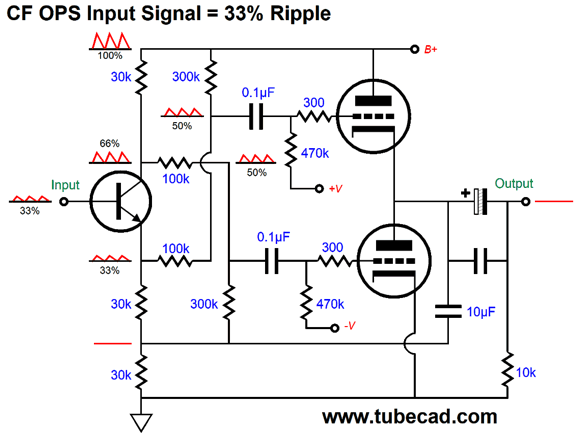
Input Signal Contains Some Power-Supply Noise
Well, we can apply this same arrangement to a transistor-based split-load phase splitter.
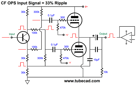
The mismatch in ratios of leaked power-supply noise is solved by both two-resistor voltage dividers, where one adds power-supply noise and the other subtracts power-supply noise. The result is that both top and bottom output tubes see the same 50% of power-supply noise, so noise null obtains at the output. Let's applied a positive pulse to the output to evaluate how the circuit responds.
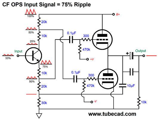
The top output tube only sees the pulse at its cathode, as it grid sees no signal. The bottom output tube sees the pulse at its plate and its grid, as the pulse was passed through the NPN transistor to its 30k collector resistor. Both output tubes work equally to counter the positive pulse, the top drawing less current, the bottom drawing more. Okay, now let's examine how we could deal with 75% of the power-supply noise appearing at the split-load phase splitter's input. This is the reverse of the 33% case, as the non-inverting output presents 75% of the power-supply noise, the inverting output presents only 25%. We must find a way to add and subtract 25% of the power-supply noise. Once again, two-resistor voltage dividers come to the rescue.
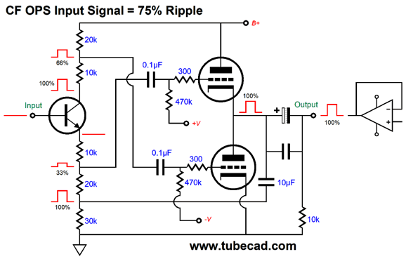
Note how both output tubes see the same amount of power-supply noise, 50%. We end throwing away some of the input gain. Just how we lose depends on the external load impedance and the output tubes' transconductance. The worst case scenario is a dead short to the ground at the output, which results in are losing 33% of the input signal to the split-load phase splitter. Now, let's perform the forced-pulse test to the output.
A +3V pulse is applied to the output and the bottom output tube sees is plate voltage rise by 3V and its grid voltage rise by 2V; the top output tube sees its cathode voltage increase by 3V and its grid voltage increase by 1V, a net change of 2V, just like the bottom output tube. In other words, both output tubes work equally to oppose the pulse. In this case, we get 66% cathode-follower functioning, so the output impedance will be equal to: Zo = 2rp/[3(mu + 1)] If the ratio of leaked power-supply noise is greater than 75%, we must increase the division ratio of both two-resistor voltage dividers. In conclusion, we saw that if the amount of leaked power-supply noise at the split-load phase splitter's input was either none or half or all, then we didn't have to throw away any signal gain. We also saw that we could alter the output stage from cathode follower to grounded-cathode amplifier functioning. The assumption behind most of the examples was that a class-A headphone OTL amplifier was the design goal. Nonetheless, all these topologies can be applied to large power OTL amplifiers. Moreover, we are not restricted to using bipolar transistors, as we could just as easily employ MOSFETs or, where the circuit made use of an NPN transistor, a triode. No doubt some are thinking: "John, John, what is with your obsession with PSRR? The answer is simple—use more capacitors and some inductors." I have heard this line of reasoning many times before. What the argument misses is that I am totally fine with adding more capacitors and inductors, but the underlining topology should sidestep as much of the power-supply noise ass possible anyway. Here is an example circuit.
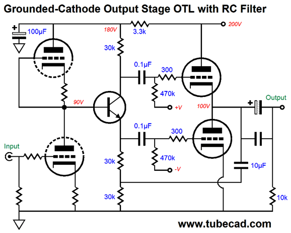
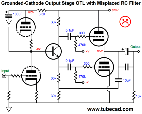
The raw B+ voltage of 200Vdc might have already come through an RC filter or LC filter. The input stage and phase splitter share the same RC filter, which is critical, as the PSRR enhancing setup only works when they do. Here is the wrong way to do it.
The idea here was that since the input stage give rise to the most noise, it should get the RC filter all to itself. Wrong. The better approach is to let the first two stages share the RC filter and let the phase splitter undo the first stage's leaking of ripple.
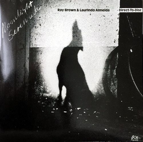
Music Recommendation: Moonlight Serenade
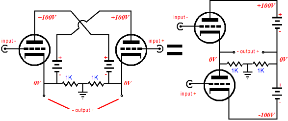
*The Exception I pointed out long ago in Cars, Planes, and Circlotron that an alternative Circlotron topology existed that would behave identically with the conventional topology, including the ability to be run in class-AB and to receive a balanced input signal of equal magnitude.
Alas, few know that this variation exists; fewer understand that it functions identically with the conventional circlotron.
One advantage it offers that it can use a single bipolar power supply per channel, rather than the two separate power supplies that the conventional circlotron uses. //JRB
If you enjoyed reading this post from me, then you might consider becoming one of my patrons at Patreon.com
User Guides for GlassWare Software
For those of you who still have old computers running Windows XP (32-bit) or any other Windows 32-bit OS, I have setup the download availability of my old old standards: Tube CAD, SE Amp CAD, and Audio Gadgets. The downloads are at the GlassWare-Yahoo store and the price is only $9.95 for each program. http://glass-ware.stores.yahoo.net/adsoffromgla.html So many have asked that I had to do it. WARNING: THESE THREE PROGRAMS WILL NOT RUN UNDER VISTA 64-Bit or WINDOWS 7 & 8 or any other 64-bit OS. I do plan on remaking all of these programs into 64-bit versions, but it will be a huge ordeal, as programming requires vast chunks of noise-free time, something very rare with children running about. Ideally, I would love to come out with versions that run on iPads and Android-OS tablets. //JRB |
John Gives
Special Thanks to the Special 88!
I am truly stunned and appreciative of their support. In addition I want to thank the following patrons:
All of your support makes a big difference. I would love to arrive at the point where creating my posts was my top priority of the day, not something that I have to steal time from other obligations to do. The more support I get, the higher up these posts move up in deserving attention.
If you have been reading my posts, you know that my lifetime goal is reaching post number one thousand. I have 531 more to go. My second goal is to gather 1,000 patrons. I have 912 patrons to go. Help me get there.
Support the Tube CAD Journal & get an extremely powerful push-pull tube-amplifier simulator for TCJ Push-Pull Calculator
TCJ PPC Version 2 Improvements Rebuilt simulation engine *User definable
Download or CD ROM For more information, please visit our Web site : To purchase, please visit our Yahoo Store: |
|||


| www.tubecad.com Copyright © 1999-2019 GlassWare All Rights Reserved |