| John Broskie's Guide to Tube Circuit Analysis & Design |
|
21 January 2019 Post 453
I hope you got the day off.
CF & Gnd-K Cascade
CF & Gnd-K Amplifier Cascade Part II
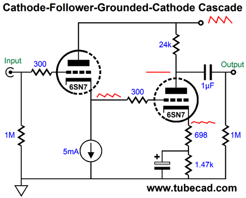
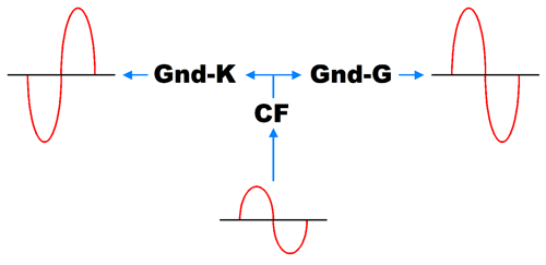
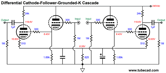
In many ways, this topology is the cousin to the cathode-coupled amplifier, but differs in that the input signal's phase gets inverted at the output. This raises an interesting possible arrangement of a triad of triodes to create a phase splitter. In other words, what if the cousins marry in a polyamorous arrangement?
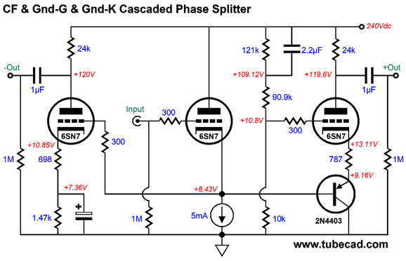
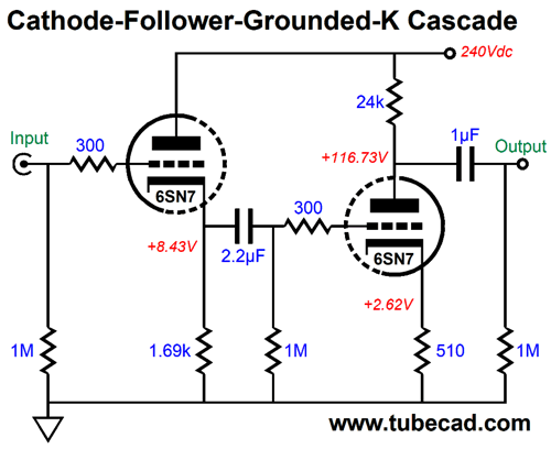
The cathode follower receives the input signal and then drives the grounded-cathode amplifier and grounded-grid amplifier. The latter is not driven directly, but through a PNP transistor. Why? We need to decouple the grounded-grid amplifier's cathode from the cathode follower's cathode or they will interact with each other; instead, we want coupling to go only one way from cathode follower to grounded-grid amplifier. If did allow the two cathodes to directly couple, our efforts at creating a power-supply noise null at the grounded-grid amplifier's output would cross-feed to the grounded-cathode amplifier's grid. Would that be bad? Yes, as the correction signal would be in the wrong phase, making a power-supply noise null at the grounded-cathode amplifier's output impossible. The cathode follower's triode is in the center; the grounded-cathode amplifier's, at the left; and the grounded-grid amplifier's, at the right. All three triodes are 6SN7 types. The grounded-grid amplifier's grid sees about 10% of the power-supply noise ridding atop the B+ voltage, which results in a deep null of the noise at the plate, where the non-inverting signal output is taken. The PNP transistor is a 2N4403, which offers a high beta (i.e. current gain). The transistor could be replaced with an N-channel FET, but its source voltage might prove too low in value. The workaround in this case would be to either increase the B+ voltage or lessen the constant-current source's current flow.
The grounded-cathode amplifier, which delivers the inverting signal output, is capacitor coupled in the schematic above, which eliminates the need for the large-valued electrolytic bypass capacitor and gives the triode more cathode-to-plate voltage. We can use the internal coupling capacitor in two-triode cathode follower and grounded-cathode amplifier cascade circuit.
Note that the coupling capacitor is larger in value than the output coupling capacitor. Why? The larger the internal coupling capacitor's value is the deeper the power-supply noise null extends into low frequencies. Ideally, we want the null to extend from 20Hz to 20kHz, but we should be happy if it goes down to 120hz, as that will be the ripple frequency with a 60Hz wall voltage. In other words, avoid the impulse to use a 0.1µF internal coupling capacitor.
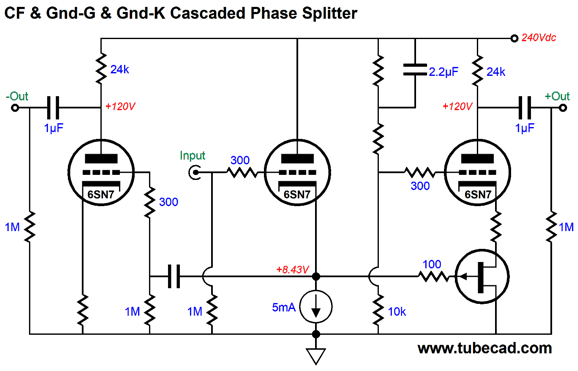
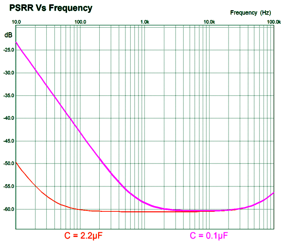
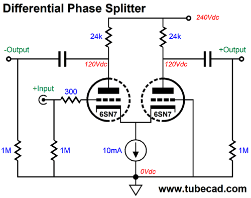
The graph reveals the difference between 0.1µF and 2.2µF internal capacitor values. In fact, a good argument could be made for using a 100µF non-polar electrolytic capacitor in this position (of course, bypassed with a small film capacitor). So, how good is this new phase splitter? And is it worth the extra effort? The best path to an answer is to compare this phase splitter to the much simpler differential amplifier based on a single 6SN7 and constant-current source loading of the coupled cathodes, operating with the same plate resistor values and the same B+ voltage.
The three-triode new phase splitter clearly wins the PSRR battle, as it offers a PSRR figure of better than -40dB, with excellent balance as well. In contrast, the two-triode differential phase splitter basically offers no power-supply rejection ratio, allowing all the power-supply noise to leak out the two outputs. In the absence of an input signal, each triode will see a constant-current flow, which means a constant voltage drop, which in turn means that the plate resistor could be replaced with zener diodes or batteries with no worsening in the PSRR, as it was already as bad as you can get. In SPICE simulations, the PSRR came in at -0.2dB for the circuit shown above, but the balance was excellent.
CF & Gnd-K Cascade with Dissimilar Triodes About 30 years ago, I built a simple cathode follower buffer line-stage amplifier that offered no gain. I named it the Unicorn, as it held a single 5687 dual triode tube. One friend labeled it the monocle, which I preferred, finding the implicit pun on glass clever. My tuner, phono preamp, and CD player all put out enough gain to drive power amplifier to full output, so I didn't need any extra gain. I was troubled by the poor PSRR, however, having expected far better performance. I did not give it a regulated power supply, as I didn't think a cathode follower needed one. My workaround was to replace the cathode resistors with constant-current sources. Bummer. The PSRR worsened. How could that be, I wondered, as all my previous additions of a constant-current source improved the PSRR. Well, I went digging in my old electronics books and I found the answer in the Electronic Designer's Handbook, by Albrecht, Davis, and Landee, which I wrote about in post 445. In short, the cathode follower's cathode resistor will always offer less leaked power-supply noise than the constant-current source.
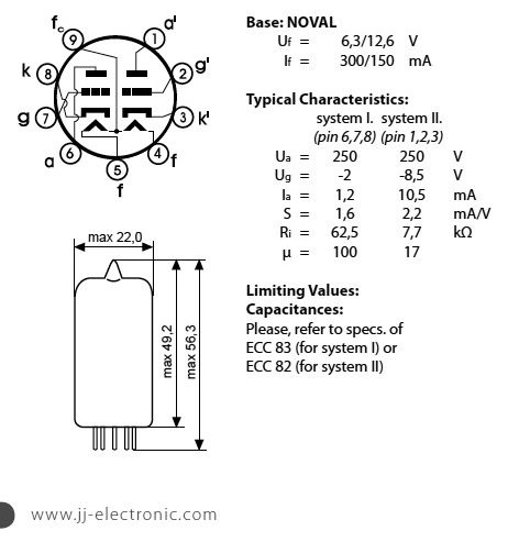
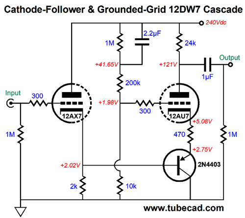
Only a handful of dissimilar-triode tubes exist. The most famous probably being the 12DW7/7247/ECC832, which holds 12AX7 and 12AU7 triodes.
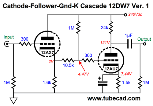
So, how well would the 12DW7 work in a CF & Gnd-K cascade amplifier? It will certainly offer low input capacitance, but its PSRR will not prove stellar, as the 12AX7 triode will not leak enough power-supply noise to create a null with the 12AU7 grounded-cathode amplifier stage. The workaround is to purposely inject more power-supply noise into the grounded-cathode amplifier's grid. How do we do that? Easy. All that is needed is two extra resistors.
The added 10.5k and 1Meg resistors define a two-resistor voltage divider that adds the needed sampling of power-supply noise. Note that the 12AU7's cathode resistor is bypassed. If it were not bypassed, the 10.5k resistor would have to be replaced with a higher valued resistor, which we do not want to do, as this resistor's resistance works into the Miller-effect capacitance of the grounded-cathode amplifier stage. The higher the resistance, the lower the high-frequency cutoff. in other words, we would be much of the main advantage using a cathode follower as the input stage. Okay, why not use lower-valued resistors in the two-resistor voltage divider? We could, but then too much current would flow into the 12AX7's cathode resistor. The workaround is to terminate the top resistor into, not the B+ voltage, but a coupling capacitor connected to the B+ voltage.
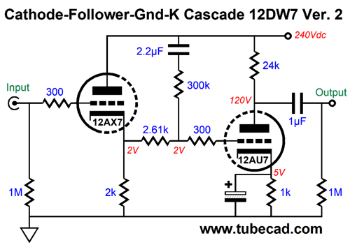
Now, the 10.5k resistor has been replaced by a 2.61k resistor and the 12AX7's cathode resistor only sees the DC current from the 12AX7. Note how we are also using a smaller-valued cathode resistor with the 12AU7. Another possible arrangement is to let the 12AX7 drive the 12AU7's cathode indirectly; in this case, with a PNP transistor. This circuit is an Aikido variation on the cathode-coupled amplifier, which means that no phase inversion result at the output.
No bypass capacitor is used on the 12AU7's cathode resistor and the 10k and 200k two-resistor voltage divider present the needed amount of power-supply noise to the 12AU7's grid to create a power-supply noise null at the plate.
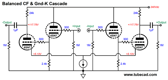
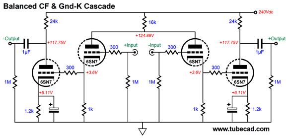
Balanced CF & Gnd-K Amplifier Cascade With the CF & Gnd-K amplifier cascade, we cannot tie the two outer triode cathodes to a shared constant-current source, which would deliver CMRR, as we would lose stellar PSRR—but we would gain stellar CMRR. If we are using a regulated power supply, this circuit would work well.
On the other hand, building a balanced CF & Gnd-K amplifier cascade does allow to use a single shared cathode resistor, which will see a voltage drop and whose bypass capacitor will not have much AC signal to shunt to ground.
We could also use a common plate resistor to feed the two cathode followers.
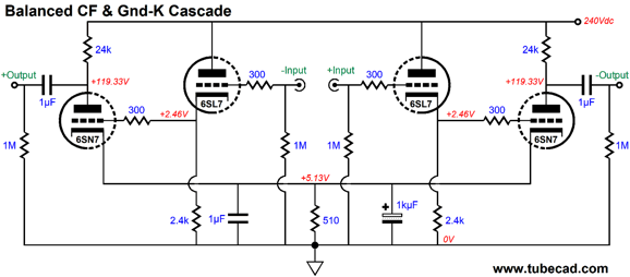
The 16k shared resistor not only lowers the input triodes dissipation, it improves the CMRR a bit. Another possibility is to use two different types of tube, say a 6SL7 and 6SN7.
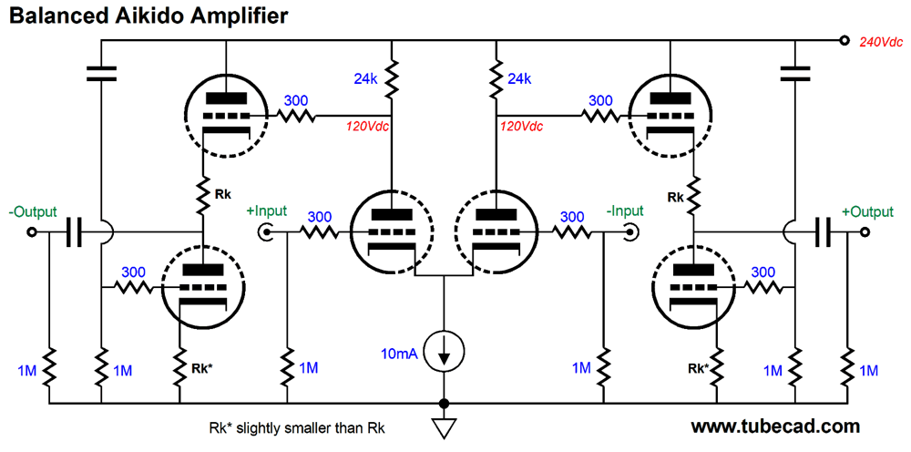
The PSRR is not as good for the circuit above, but it is still a respectable -23dB. We could improve the PSRR by adding two sets of voltage dividers. Still, I would go the Aikido differential route myself, although it does require an additional tube, as the both the PSRR and CMRR would prove first rate; moreover, the output impedance will be vastly lower.
The only downside is that the input capacitance is higher. One workaround is to cross-couple small capacitors from plate to opposing grid. This technique was standard fare in the old days, but it is tricky, as too much capacitance can lead to instability.
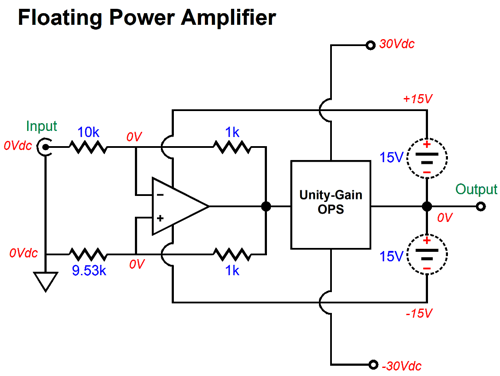
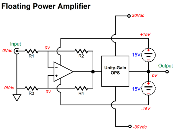
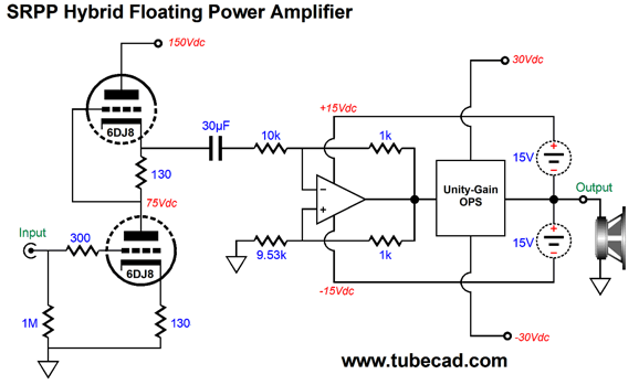
Floating Power Amplifier
The unity-gain output stage attaches to the fixed +/-30V power-supply rails, while the OpAmp attaches to the floating +/-15V power-supply rails. The OpAmp never sees more than a 30V differential, so a typical, low-voltage OpAmp can be used in an otherwise high-voltage power amplifier. As the OpAmp's output swings positively, so, too, does the unity-gain output stage's output and the +/-15V floating power-supply rail voltages.
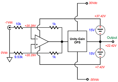
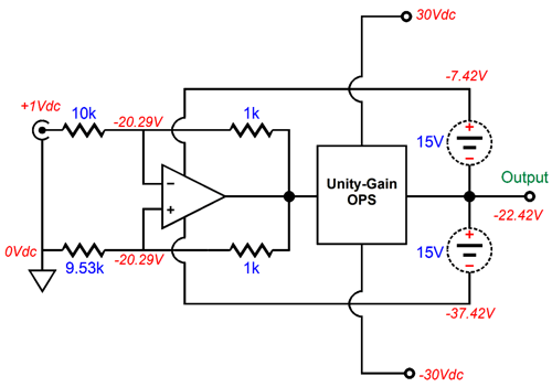
Note the negative input signal. This amplifier is set up as an inverting type. Also note that -1V in resulted in +22.42V out and that both of the OpAmp's inputs see the same +20.29V. If the input signal is positive, then the amplifier's output will swing negatively.
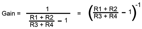
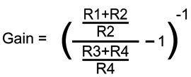
The formula for the floating amplifier's gain is the following:
where R2 = R3. If they do not equal, then we have to do three divisions, not one: Okay, here is a quick quiz: What is this amplifier's input impedance? Is it 10k or 11k or something else? The answer is that it is a bit less than 500 ohms. Not what you expected, right? Think about it: -1V goes in and +22.42V comes out, so we find the current flow through the 10k input resistor by adding voltages and resistances and then doing the division, (Vout- Vin)/(R1 +R2) = Ipk; in this example, (22.42 - -1)/(10k + 1k) = 2.13mA, which implies an input impedance of 470 ohms, as 1V / 2.13mA equals 470. Here is the problem, such a low input impedance requires a big current swing from a line-stage amplifier, as the load impedance is closer to that of a headphone than the typical amplifier.
One possible driver circuit would be an SRPP that has been optimized for the 470-ohm load impedance. That's right: the SRPP is not being used non-gratuitously here, as it must drive a low-impedance load.
A 6DJ8 is used and the SRPP invert the phase at its output, but as the rest of the amplifier also inverts, we end up with no phase inversion. A 30µF coupling capacitor is used to ensure low-frequency bandwidth. As I look at this design, I see that the gain is too high for the +/-30V power-supply rail voltages. Much higher rail voltages, say +/-70V, would take better advantage of the high gain and would allow much more power output, as in over 200W into 8-ohm loads. Still, this is an interesting hybrid design. By the way, if you try modeling it in SPICE, start slowly, beginning with just the solid-state half, as the SPICE engine might balk at converging. (Try a different OpAmp model, it you run into problems). Another by the way, the assumption behind floating amplifiers is that 0.1% resistors will be used around the OpAmp. By the way, the two 1k feedback resistors can and should extend out and attach to the output.
Music Recommendation: Bruno Bavota's RE_CORDIS Well, after my second listening, I agreed with Tidal, this was classical music. The real tests will be a year from now, then a decade from now, and finally a century from now. If music lovers still want to hear it after 100 years, it is surely classical music. I went searching to find out who he was. Here is what SoundCloud had to say:
That sounds about right. //JRB
User Guides for GlassWare Software
For those of you who still have old computers running Windows XP (32-bit) or any other Windows 32-bit OS, I have setup the download availability of my old old standards: Tube CAD, SE Amp CAD, and Audio Gadgets. The downloads are at the GlassWare-Yahoo store and the price is only $9.95 for each program. http://glass-ware.stores.yahoo.net/adsoffromgla.html So many have asked that I had to do it. WARNING: THESE THREE PROGRAMS WILL NOT RUN UNDER VISTA 64-Bit or WINDOWS 7 & 8 or any other 64-bit OS. I do plan on remaking all of these programs into 64-bit versions, but it will be a huge ordeal, as programming requires vast chunks of noise-free time, something very rare with children running about. Ideally, I would love to come out with versions that run on iPads and Android-OS tablets.
//JRB
|
|
John Gives
Special Thanks to the Special 74
I am truly stunned and appreciative of their support. In addition I want to thank the following patrons:
All of your support makes a big difference. I would love to arrive at the point where creating my posts was my top priority of the day, not something that I have to steal time from other obligations to do. The more support I get, the higher up these posts move up in deserving attention. Only those who have produced a technical white paper or written an article on electronics know just how much time and effort is required to produce one of my posts, as novel circuits must be created, SPICE simulations must be run, schematics must be drawn, and thousands of words must be written. If you have been reading my posts, you know that my lifetime goal is reaching post 1,000. I have 554 more to go. My second goal is to gather 1,000 patrons. I have 929 patrons to go. Help me get there.
Only $12.95 TCJ My-Stock DB
Version 2 Improvements *User definable Download for www.glass-ware.com |
||


| www.tubecad.com Copyright © 1999-2019 GlassWare All Rights Reserved |