| John Broskie's Guide to Tube Circuit Analysis & Design |
|
15 April 2018 Post 420
Being self-employed never sucks as much as it does on this day, as we self-oppressors of the selfsame noble and downtrodden proletariat never get so hosed by the government as on this day. By the way, "proletariat" has a great etymology, as it comes from the Latin word that denoted the lowest class of Roman citizen, whose only contribution to the state was offering children.
More Single-Ended OTL Designs
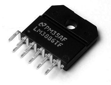
Ideally, Texas Instruments or Analog Devices should come out with a big IC that looks just like a LM3886 or OPA541, but holds a power unity-gain power buffer inside. It could be either a high-negative-feedback design or a feedback-free effort. Power output of 50W to 100W would be welcome. Even more welcome would be the ability to easily parallel them. Why? Imagine putting four 50W buffers in parallel so that 200W could be delivered to a loudspeaker. By the way, 200W into 8-ohm loads requires peak voltage swings of 56.5V and a peak current swing of 7.06A. In other words, with bipolar power-supply rail voltages of +/-60V and four power buffers we could build the most amazing tube-solid-state hybrid amplifiers.
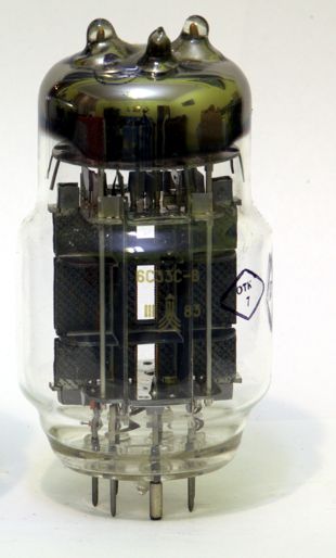
Before I go any further, I must absolutely stress one key point: the 6C33C* is merely a convenient example of a power triode, not an absolute necessity. Other triodes, albeit several in parallel, could replace the 6C33C. For example, several 6AS7 or 6082 triodes or El509 pentodes could be used, with some minor adjustments to bias voltages. Besides, who knows what the future will offer, as a new power triode could be in the works now. I often, all too often, get email that asks if the circuit that I had shown and which held a 6SN7 could use a 12AU7 instead; invariably the answer is yes. More maddening are email that ask if an NOS Tungsol 6SN7 could be used, rather than an NOS RCA 6SN7—seriously! Topology is what stands independent of the given example.
Returning to the problem of now ready-made power buffers, we could of course roll our own. In many ways this is the best route, as we can go all and spread the heat across several TO-247 power transistors or MOSFETs. In addition, the capacitors that appear within ICs are of very poor quality, when compared to those that exist outside the IC. Another possibility is to use an existing power-amplifier IC, such as the LM1875 and LM3886, which are not unity-gain stable. The workaround is to let the amplifier amplify at its lowest, safest limit, and then feed it an inversely attenuated input signal. For example, if its gain is set to 10, we would feed it 1/10th the input signal that we would feed a unity-gain buffer.
This is not ideal, as we waste gain, but it is a expedient workaround. Since a schematic is worth at least 1,000 words, we will move on to some design examples.
16W Single-Ended OTL with IMC Wattage AC = I² · R/2 Since current is squared, a doubling of current equals a quadrupling of power output and a fourfold increase in current equals a sixteen-fold increase. Now we are talking, as 16W can make a lot of sound, particularly in small rooms and with high-efficiency loudspeakers. So, how do we get to 2A of peak current swing? Answer: we use an impedance-multiplying circuit (IMC) to make the loudspeaker seem many times higher in impedance than it actually is.
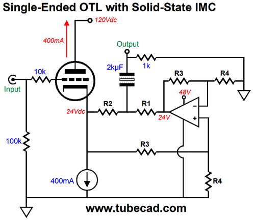
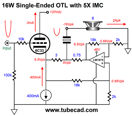
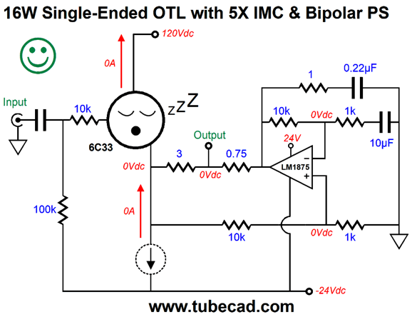
This is the generic overview. Now, here is a fleshed out version.
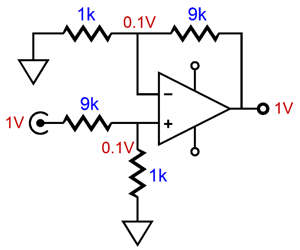
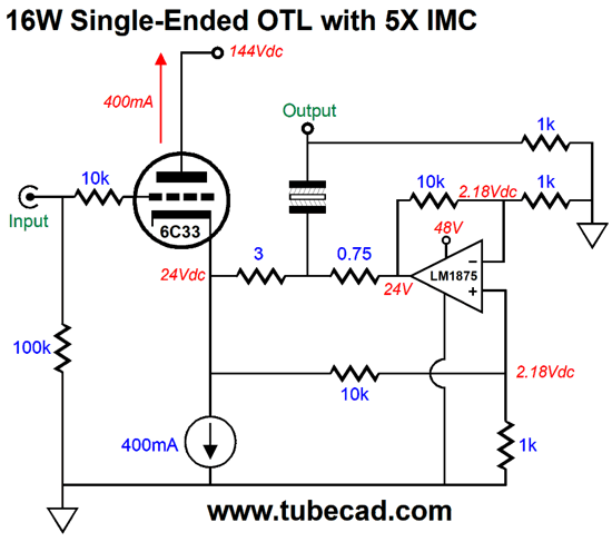
The first confusing thing is that the 6C33's idle current in this example is 400mA, not 500mA. Why? I fear for the triode's life span, as 500mA is a raging torrent of current flow for any triode, including the 6C33. The second confusing aspect of the circuit above is the two-resistor voltage divider made up the 10k and 1k resistors. This attenuator DC couples to the 6C33's cathode and terminates into ground. The voltage divider reduces both the AC and DC signal at the cathode by 1/11 or by 0.0909. The solid-state power amplifier's 10k and 1k negative feedback resistors set a gain of 11, which undoes the two-resistor voltage divider's 1/11th attenuation, bringing us back to unity gain. In other words, this circuit is functionally equal to this one from my last post.
The only functional difference is that one circuit uses a unity-gain buffer, while the other uses an amplifier with input attenuator. Well, since many chip amplifiers are available, which one should we use? One that readily comes to mind is the LM1875, which is a five-lead power amplifier in a TO-220 package and which cost about $3 each. It is rated for 25W of output and can withstand a negative-to-positive power-supply rail voltage of 60V.
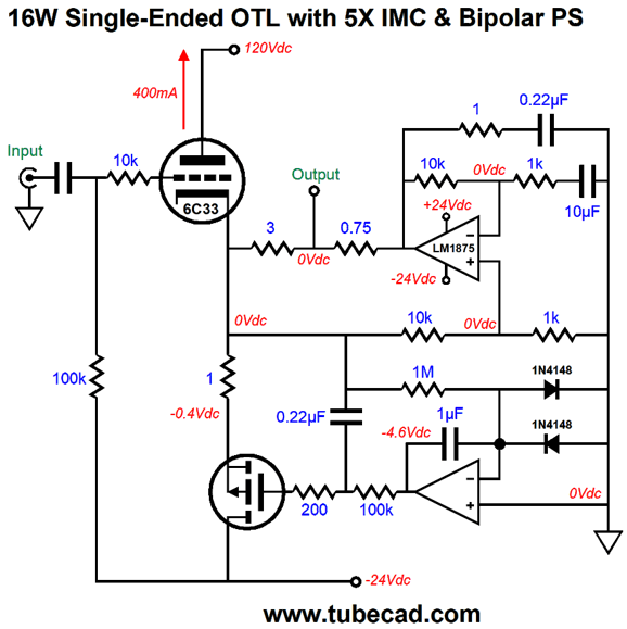
Its precursor was the LM675 and I know several audiophiles who quite like the sound from the LM1875. The 3-ohm and 0.75-ohm resistors set the IMC ratio of 5:1, as (3 + 0.75)/0.75 = 5; thus, an 8-ohm loudspeaker appears as a 40-ohm load to the 6C33 (actually, the 3-ohm resistor adds to the total, so 43-ohms is the actual impedance seen by the triode.) We find the peak possible voltage swing by multiplying 0.4A against 40 ohms, which gives us 16Vpk, which in turn gives us 16W into an 8-ohm load, W = V²/2Rload. The peak current swing into the 8-ohm loudspeaker will be 16V/8 or 2A. This means that the LM1875 will have to deliver the missing 1.6A, which implies that the load the LM1875 sees is 10 ohms. By the way, if we place 10-ohm and 40-ohm resistances in parallel, we get 8 ohms. By the way, no doubt some are thinking that the constant-current source could be replaced by a big resistor; and, maybe, a few imagine that we could use two resistors in series, which would allow us to lose the two-resistor voltage divider. We can, but I don't recommend it.
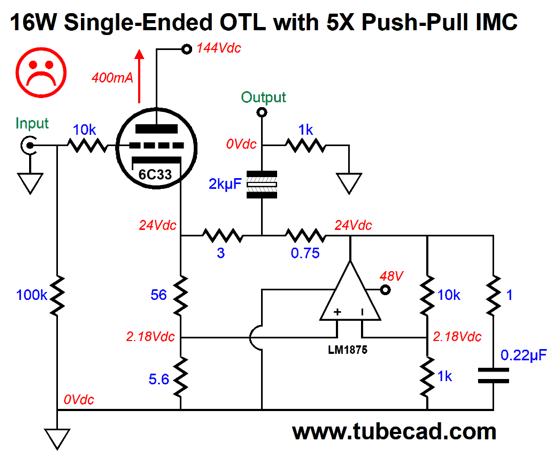
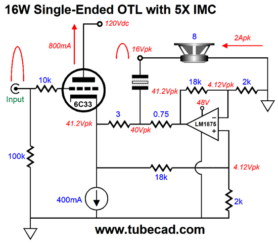
The 56-ohm and 5.6-ohm resistors will set the idle current to about 400mA and they will also divide the cathode voltage by 11, but these cathode resistors will not deliver anything close to 16W of output power. Why not? These resistors are not constant-current sources; their current conduction varies with the voltage drop across them. Moreover, the 61.6-ohm load is effectively in parallel with the 43-ohm impedance presented by the IMC. On the other hand, we could replace the constant-current source with an inductor, which behaves like a constant-current source in terms of AC currents. (The 1-ohm resistor and 0.22µF capacitor were taken right out of the LM1875 data-sheet. The 48V power-supply voltage for the LM1875 could come from a 48Vdc desktop switcher power supply or a simple power supply made up of four rectifiers, a large reservoir capacitor and power transformer.) Let's put the constant-current source back in the circuit and see how it works. With a large positive input signal, the triode will double its idle current. I switched both the LM1875's negative feedback resistors and the two-resistor voltage divider resistors to 18k and 2k, as that ratio will produce a gain of 10 from the LM1875 and voltage division of 1/10 from the two-resistor voltage divider, which should make the voltage relations more obvious.
We don't get the full 800mA of triode current flow, as we must subtract the constant-current source's draw of 400mA, so only 400mA travels to the external load impedance. Note how both the IMC and the triode's cathode present the same peak voltage of 41.2V. The 8-ohm loudspeaker sees +16V of peak voltage swing and a peak current flow of 2A. Now, let's apply a large negative input signal to the triode's grid.
The cathode voltage drops to 6.8V and the triode ceases to conduct any current, so all of the constant-current source current flows into the external load impedance. The 8-ohm loudspeaker sees -16Vpk and a peak current flow of -2A. The output coupling capacitor's value (2kµF) allows bandwidth down to 10Hz. A non-polarized electrolytic should be used, bypassed by a quality film or PIO capacitor.
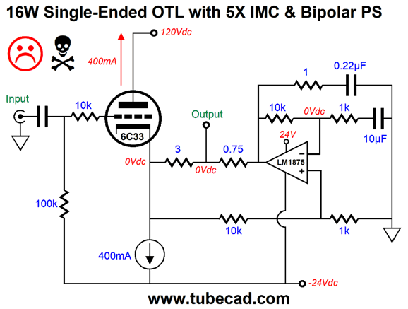
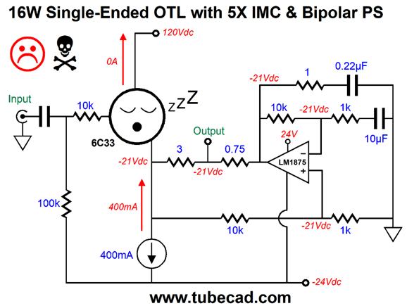
Single-Ended & IMC with Bipolar Power Supply
The first problem we encounter is that the output triode's cathode might not settle at 0Vdc, as it could easily fall between -1V to +1V. In addition, at start-up, the triode will be cold and not conducting any current, but the constant-current source will be conducting, which will throw the output severely negative.
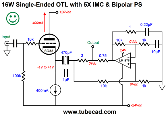
The easiest workaround is to place a coupling capacitor at the triode's cathode.
This coupling capacitor is much smaller in value, as the load seen by the cathode is five times higher than what the loudspeaker actually presents. In contrast, the impedance-multiplier circuit (IMC) is DC coupled to the loudspeaker. So is this amplifier actually capacitor coupled or direct coupled or some mix of both? The important feature is that even if the triode is missing from its socket, the loudspeaker is safe.
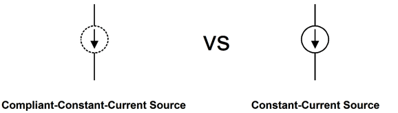
Another workaround is to replace the constant-current source with a complaint-constant-current source (CCCS), which behaves much like an inductor in that it does not establish a fixed current flow, but mimics the flow of current from the triode; but unlike an inductor, the CCCS displaces voltage. In fact, it strives to eliminate a DC offset voltage at the loudspeaker terminal.
Even if the tube is cold, the CCCS will not draw any current, so the loudspeaker is safe. My last post showed how to use an N-channel MOSFET to make a CCCS circuit.
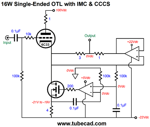
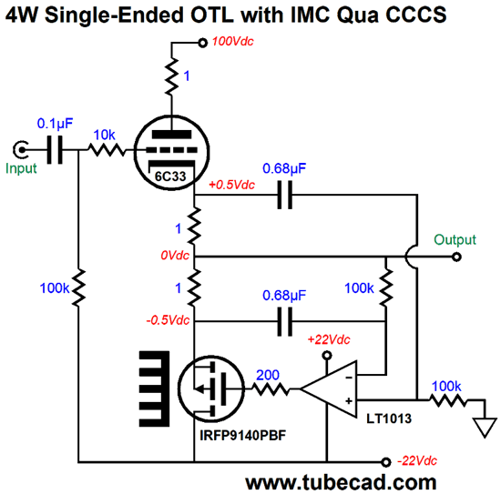
We can, however, use a P-channel MOSFET instead.
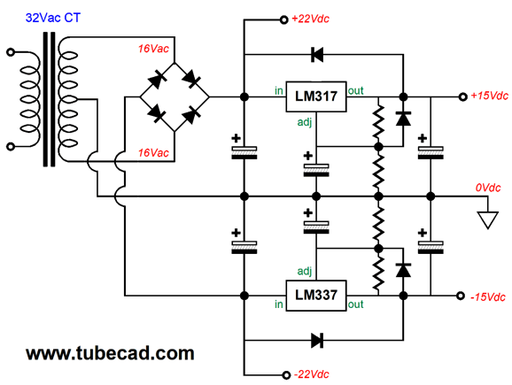
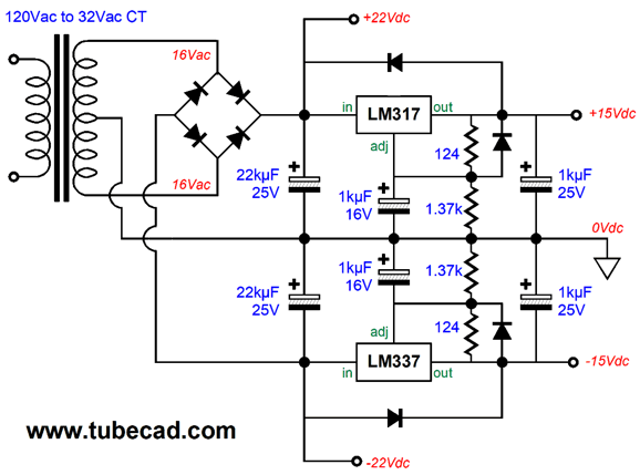
The P-channel MOSFET functions as a source follower and the 0.22µF capacitor that attaches to the output relays the amplifier's output to the MOSFET's gate, so the MOSFET's source follows the output and presents a very high output impedance. The OpAmp is configured as a DC servo and it strives to eliminate any DC offset at the output. We can either use a high-voltage OpAmp or we can regulate down the bipolar power supply rail voltages to +/-15V.
The 32Vac center-tapped secondary rectifies into +/-22Vdc, which will power the LM1875 directly, while the two regulators drop the +/-22V to +/-15V.
As you can see, none of the needed parts are exotic or expensive.
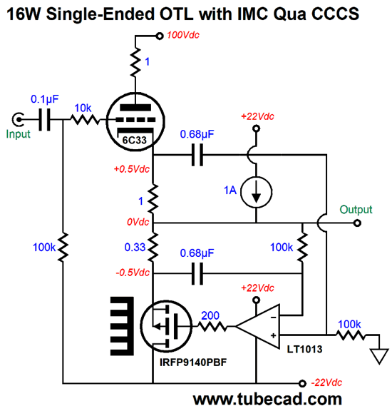
Push-Pull OTL with IMC Qua CCCS Returning to the world of electronics, I bet that more than a few were put off by the inclusion of the LM337 negative regulators in the last post's somersault circuit. Why? They found them uncouth.
This got me thinking about how to make a discrete version of the LM337. Internally, the LM337 holds a power PNP transistor, OpAmp, and voltage reference. Finding three separate replacements is easy enough, but then I began to query the necessity of the voltage reference. I wondered, what if we replaced the voltage reference with a capacitor? We would certainly lose the constant-current source aspect, as the circuit would no longer strive to maintain a fixed idle current. At the same time, we would gain a compliant-constant-current source feature, which is cool.
This arrangement will perform two important tasks: it will match the idle current of the 6C33 and it will work to prevent a DC offset at the output. Moreover, this arrangement will allow push-pull operation of the 6C33, so twice the idle current (0.5A) can be delivered to the loudspeaker, thereby increasing the power output by fourfold. The LT1013 is a high-voltage OpAmp that will work with the +/-22Vdc power-supply rail voltages. At idle, the P-channel MOSFET will dissipate about 11W, which is toasty, but not insanely hot. Indeed, with a large enough heatsink, we could get even more watts.
The added 1A constant-current source is in parallel with the triode and constantly pulls up, so the P-channel MOSFET will have to pull down extra hard to keep the output a 0V at idle. In other words, the MOSFET will have to draw as much current as the triode and constant-current source combined or 1.5A, which will bring the MOSFET's dissipation up to 32.25W. What we gain with the constant-current source addition is more power output, as the 4W will be replaced by 16W.
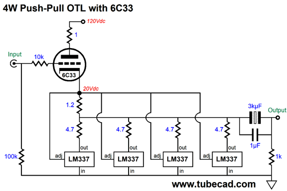
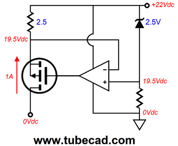
In SPICE simulations, this circuit worked surprisingly well, which surprised me. Why? This is a single-ended/push-pull class-A output stage after all, but I expected clipping on negative waveforms, as I didn't expect the OpAmp to be able to drive the P-channel MOSFET sufficiently negative. It turns out that I forgot that the LT1013 is a rail-to-rail design. in other words, the expensive workaround I envisioned of using a lateral MOSFET instead will not be needed. (In fact, this topology seemed to work so well that my mind quickly envisioned a version bigger power-supply-rail voltages and a 3A constant-current source and six to eight P-channel MOSFETs. Why? We could get 64W of output, with just one 6C33C per channel. Why so many MOSFETs? Class-A operation.) How do we make a 1A constant-current source? We could use two LM317-HV, configured as constant-current sources in parallel or we could go the discrete route.
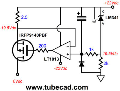
Another P-channel MOSFET is used with another OpAmp. The voltage reference's 2.5V voltage is then superimposed across the 2.5-ohm source resistor, which establishes a fixed current flow of 1A. Now, let's flesh out the design.
The LM431 is a shunt regulator that can be used to establish a 2.5V voltage reference. The low-pass RC filter is made up from the 1k and electrolytic capacitor. The diode provides a discharge path for the big capacitor. Also note that the OpAmp now sees a 44Vdc differential, not 22Vdc as was the case in the previous schematic. Where do we buy a 2.5-ohm resistor, as they don't make them, as far as I know? They do make 10-ohm/1W resistors, so four in parallel would develop 2.5 ohms of resistance.
An 8-Ohm/32-Ohm Loudspeaker My guess is that for every tube-amplifier builder there are four or five loudspeaker builders. When I lived in Silicon Valley, we were lucky to get 30 tube-fanciers together, in spite of the highest concentration of electronic geeks in the USA. In contrast, I have been to speaker-builder get-togethers in a remote town where 50 builders showed up. Why the difference? The little that cannot be explained by the fear of high-voltages can be explained by how much fun woodworking projects can be. In addition, pre-assembled crossovers are sold, so very little, if any, soldering is required to build a loudspeaker. I do not want to paint anyone into a corner, so the ideal high-impedance loudspeaker would be one that could easily convert into the standard 8-ohm loudspeaker at the flip of a switch. This means that some high impedance work better than others; for example, 32-ohm and 72-ohm speakers can easily be reordered into 8-ohms speakers. A 32-ohm loudspeaker can be made from two 16-ohm woofers in series and in a D'Appolito configuration, where the two woofer straddle a tweeter.
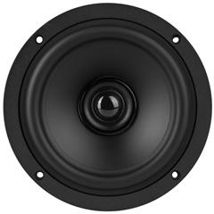
The single tweeter can be an 8-ohm driver with a 24-ohm resistor in series. The tweeter, in this case, must be 12dB more efficient that the woofers. Since each woofer sees half of the signal voltage, we lose 6dB; but as we have doubled the emitting surface, we gain 6dB, a net total of 0dB. With the 8-ohm tweeter (they don't make 16-ohm tweeters as far as I can tell), we place a 24-ohm resistor in series, so we lose 12dB, but since we have the same emitting surface, we must incur the -12dB penalty. Note well that this penalty, as it means that we cannot simply take an existing finished 8-ohm loudspeaker and place a 24-ohm power resistor in series with it, as all we would gain is a 24-ohm output impedance and a hot resistor. In contrast, four finished 8-ohm loudspeaker enclosures stacked together and wired in series would retain the power amplifier low output impedance and deliver much higher SPL with an OTL amplifier. With a solid-state power amplifier, which can pour a deluge of current but put only swing a few tens of volts, the 32-ohm load impedance is a liability. On the other hand, if the four speaker enclosures are wired in series-parallel, with a resulting 8-ohm impedance, the solid-state power amplifier will seem to be four times more powerful, as the four loudspeakers produce 6dB more SPL over what one of the loudspeakers would produce with same amplifier. In other words, a 100W amplifier would play as loudly as a 400W amplifier. I have actually heard eight small two-way BBC-monitor style speaker boxes hooked up with four per channel, one atop another, with one speaker facing forward, one facing the back wall and two facing the closest side wall. Amazing. Simply amazing. One 5-inch woofer can barely grab hold of enough air to make much bass reproduction, but four so arranged speakers could. The imaging was first-rate and symphonic music actually sounded symphonic. With two boxes facing backwards and two facing forward, Woodstock sounded live. In many respects, this was a wasteful effort, as each channel only required one crossover, not four. But in terms of sonic enjoyment, this setup was a bargain. Okay, that was a long side-trip, so let's return to the 32-ohm loudspeaker made from two 16-ohm drivers. For example, FaitalPRO makes a 4" full-range driver with a 16-ohm impedance, whose efficiency is 91dB @ 1w @ 1meter. But 1W with a 16-ohm load means 5.65Vpk, not the 4Vpk (2.83Vavg) that an 8-ohm speaker requires. So we have an apple and oranges problem. If we applied 4Vpk (2.83Vavg) to the 16-ohm speaker, its efficiency would be 3dB less, bringing it down to 88dB. The tweeter must be 12dB more efficient (100dB), as the 24-ohm series resistance will drop the tweeter's SPL by -12dB. In other words, a horn-loaded tweeter is the most likely candidate. With the two woofers in parallel, resulting in an 8-ohm load, the efficiency would rise by +6dB due to the doubling of emitting surface area, bringing the total up to 94dB. Fortunately, 100dB tweeter can still be used with a -6dB padding attenuator, which could be made out of three 8-ohm resistors, the same resistors that in series equal 24 ohms.
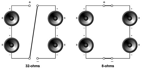
This turned out to be a tad more complicated than I expected, so let's use four 8-ohm full-range drivers in the next example. Four 8-ohm drivers in series equals 32 ohms; and four in series-parallel configuration equal an 8-ohm load.
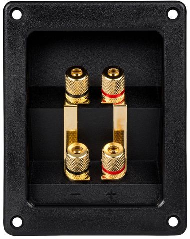
We could do the wiring externally to the loudspeaker by using a bi-wire four-terminal hookup plate
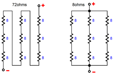
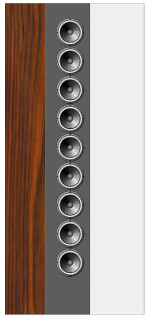
The other easy impedance is 72 ohms, as nine 8-ohm drivers in series equal 72 ohms, but a three by three grid equals 8 ohms.
When configured as a 72-ohm load, each driver gets 1/9 as much voltage drop, but since we increased the emitting surface area by nine-fold, it's a wash, so 4Vpk across the 72-ohm load gives 88dB, assuming 88dB efficient drivers. But the same 0.5Apk (36Vpk) across the 72-ohm load yields +19dB more SPL, bringing the total to 101dB. When configured as 8 ohms, each driver sees one third the voltage drop, so each incurs a 9.5dB loss in SPL, but with nine times the surface area, we gain 19dB, a net gain of 9.5dB, bringing the total to 97.5dB. Not bad.
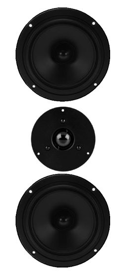
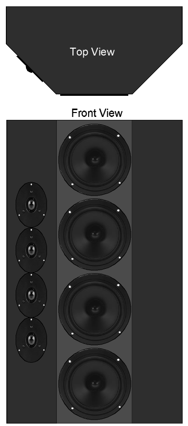
See post 195, for more details on the 72-ohm speaker shown above. The only problem with 72 ohms is that the OTL will probably run out of voltage and may become current limited as well, particularly with output triodes. So, a 32-ohm loudspeaker is probably the best choice. One possible loudspeaker design would be a two-way with four woofers and four tweeters.
In this example, the tweeter does not need to be more efficient than the woofer. I would build two crossovers in the enclosure, each designed with a 16-ohm load in mind.
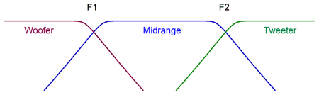
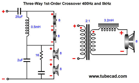
The crossover is a 5kHz second-order Linkwitz-Riley type, -6dB down at crossover frequency but sums to unity, with my impedance flattening circuit. Note the phase reversal on the woofers. If you prefer, revrse the tweeter's phase instead. These crossovers and driver configurations can be placed in either series or parallel; hence the 32-ohm or 8-ohms choices. In other words, each speaker cabinet would hold two crossovers and two 16-ohm speaker arrays. The best theoretical crossover is the first-order crossover, as it alone preserves phase integrity. Alas, it is also the most difficult to realize in actual use, as it assumes drivers with far greater bandwidth than reality likes to provide. Having said this, we might be able to get away with a first-order crossover if we make a three-way loudspeaker.
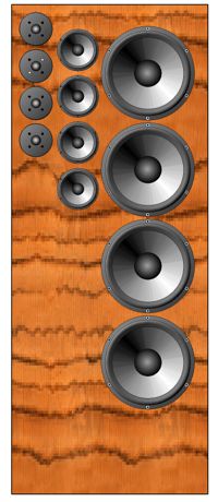
If we add a 400Hz crossover point to the mix and cascade the tweeter's signal through the 400Hz and 5kHz first-order crossovers, then might be able to get away with the shallow slopes. Yes, this would entail adding four bigger woofers, say four 6-in or 8-in woofers.
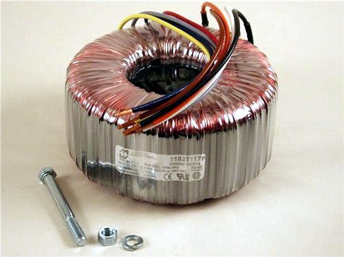
Another seemingly crazy idea is to use an audio output transformer with a winding ratio of only 2:1, which implies an impedance ratio of 4:1, so a single 8-ohm woofer would appear as a 32-ohm load to the OTL amplifier. Let's return to the OTL power amplifier that can deliver 2A of peak current swings, but 64V of peak voltage swings. Into an 8-ohm load, the 2A current limit results in a 16V voltage limit, so only 16W of power are delivered. In other words, we only get one fourth of the potential 64W of power from the OTL with the 8-ohm loudspeaker. But into a 32-ohm load, the full 64W of power are realized. Now, a step-down transformer with two-to-one winding ratio will deliver 32Vpk and 4Apk into an 8-ohm woofer, which equals 64W.At full output, the four midranges and four tweeters, each of which individually offers an efficiency of 88dB per watt at one meter, will create an SPL of 112dB; thus, the woofer will have to offer an efficiency of 88dB + 6dB to make 112dB, so a 94dB SPL rated woofer is required. Pro-audio woofers can easily meet this requirement, but few hi-fi woofers can. Attention, John, Earth calling. Where do you think you are going to find a transformer with such a crazy-low winding ratio that can handle 64W of power? Oh, that was the least of my concerns. Now, if a high-end-audio company sold such a transformer, we would expect to pay at least $500 for one. Fortunately, 225VA 60Vac toroidal power transformers can be bought for $71 each at Mouser.com. (For $10 to $20 more, we can buy a 300VA transformer.) The high VA rating ensures that frequencies below 50Hz can be reproduced with gusto. Remember, with every halving of the low-frequency cut-off frequency, we must use a four times bigger output transformer to pass the same wattage.
When toroidal power transformers first appeared on the scene in the 1980s, I bought several and measured them as audio output transformers. The lower the winding ratio, the better the performance, with the 1:1 isolation transformer proving the best. Since the woofer will only cover frequencies from 40Hz to 400Hz, bandwidth out to 4kHz would be plenty.
In general, audio products follow a 1 to 5 rule, where $100 of parts end up making an audio product that cost $500 to the consumer. So, if a loudspeaker company bought these same toroidal power transformers at $40 each, they would raise the cost of each speaker by $200; possibly more, due to higher shipping costs and the more rugged construction required.
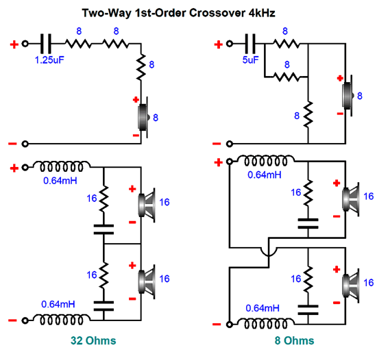
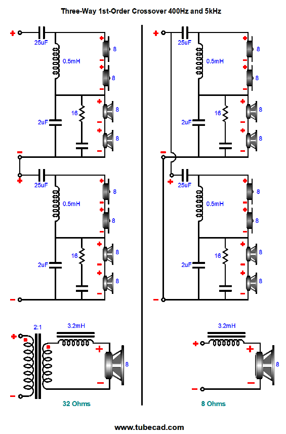
Note how the tweeters see two cascading high-pass filters, not one (400Hz and 5kHz). In other words, each speaker cabinet will hold one 8-ohm woofer, which can couple through the step-down transformer or directly; and two 16-ohm crossover and driver cluster, which can be either placed in series for 32 ohms or placed in parallel for 8 ohms.
On the left side, we see a 32-ohm load; on the right, an 8-ohm load.
By the way, what I like about this potential loudspeaker setup, other than the switchable load impedance, is that the four woofers and four tweeters sit in a narrow width of board. In addition, the woofer and tweeter voicecoils are closer to being in time alignment. Moreover, both woofers and tweeters will be heard slightly off axis, which is my clear preference. Straight on, most dynamic speakers seem to blare, much like looking into a flashlight beam directly; but slightly off axis sound much more even-sounding.
Dayton Audio now sells 4-in and 5-in coaxial drivers that hold silk dome tweeters in their center. Placing four in a line array might make a great-sounding speaker.
Music Recommendations I happen to like getting personal recommendations. Over the years, several readers have written to me, asking how they could repay me for some circuit I created that they built and loved. In response, I asked them to send a copy of their favorite CD. Now on my own, I might have quickly dismissed the CD, had I picked it up from the library or a garage sale. But as it was imbued with their personal stamp of appreciation, I listened harder and more attentively than I might have otherwise. Invariably, I discovered what was cherished about the album. This post's recommendation is any album by Holly Cole. Wikipedia tells us that "Holly Cole is a Canadian jazz singer, particularly popular in Canada and Japan for both her versatile and distinctive voice, along with her adventurous repertoire, which spans such divergent genres as show tunes, rock, and country music." I will tell you that she should be vastly better known here in The States. Often singers are no match to the songs they sing. Not Holly. She effortlessly makes every song she sings her own.
All her CDs are well worth a listen, but for audiophiles, the best choice is her album, Temptation. Recorded in 1995, this was her third album and it consists entirely of covers of Tom Waits songs.
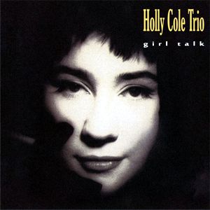
Every track bestows audiophile bliss, but the second track, Train Song, will test your systems imaging and deep bass. Another album, which was recorded live with a single microphone, is Girl Talk. Try theses two songs, Cruisin' and Downtown. Since I know audiophiles so well, I can anticipate that a few will bail on the song Cruisin' before the saxophone comes in; don't.
When searching Tidal, be sure to search for both "Holly Cole" and "Holly Cole Trio" to see all the albums available at Tidal. Highly, highly recommended.
//JRB
*6C33C https://www.google.pl/url?sa=i&rct Thanks Ziggy.
User Guides for GlassWare Software
For those of you who still have old computers running Windows XP (32-bit) or any other Windows 32-bit OS, I have setup the download availability of my old old standards: Tube CAD, SE Amp CAD, and Audio Gadgets. The downloads are at the GlassWare-Yahoo store and the price is only $9.95 for each program. http://glass-ware.stores.yahoo.net/adsoffromgla.html So many have asked that I had to do it. WARNING: THESE THREE PROGRAMS WILL NOT RUN UNDER VISTA 64-Bit or WINDOWS 7 & 8 or any other 64-bit OS. I do plan on remaking all of these programs into 64-bit versions, but it will be a huge ordeal, as programming requires vast chunks of noise-free time, something very rare with children running about. Ideally, I would love to come out with versions that run on iPads and Android-OS tablets.
//JRB
|
|
John Gives
Special Thanks to the Special 69
I am truly stunned and appreciative of their support. In addition I want to thank
All of your support makes a big difference. I would love to arrive at the point where creating my posts was my top priority of the day, not something that I have to steal time from other obligations to do. The more support I get, the higher up these posts move up in deserving attention. Only those who have produced a technical white paper or written an article on electronics know just how much time and effort is required to produce one of my posts, as novel circuits must be created, SPICE simulations must be run, schematics must be drawn, and thousands of words must be written. Only those who have produced a technical white paper or written an article on electronics know just how much time and effort is required to produce one of my posts, as novel circuits must be created, SPICE simulations must be run, schematics must be drawn, and thousands of words must be written. If you have been reading my posts, you know that my lifetime goal is reaching post number one thousand. I have 580 more to go. My second goal is to gather 1,000 patrons. I have 931 patrons to go. Help me get there.
Only $12.95 TCJ My-Stock DB
Version 2 Improvements *User definable Download for www.glass-ware.com |
||


| www.tubecad.com Copyright © 1999-2018 GlassWare All Rights Reserved |