| John Broskie's Guide to Tube Circuit Analysis & Design |
31 July 2017 Post Number 390
Special Thanks If you have never produced a technical white paper or written an article on electronics, you probably cannot imagine how much time and effort is required to produce one of my posts. If you have been reading my posts, you know that my lifetime goal is reaching post number one thousand. I have 610 more to go. I should easily be able to hit post 400 this year and reach my half-way point (500 posts) in a few years. My second goal is to gather 1,000 patrons. I have 958 patrons to go. If you enjoyed reading this post from me for the last 18 years, then you might consider becoming one of my patrons at Patreon.com. It would make a big difference to me. Thanks.
Quick Chromecast Audio Update
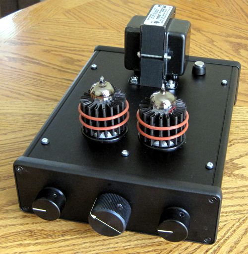
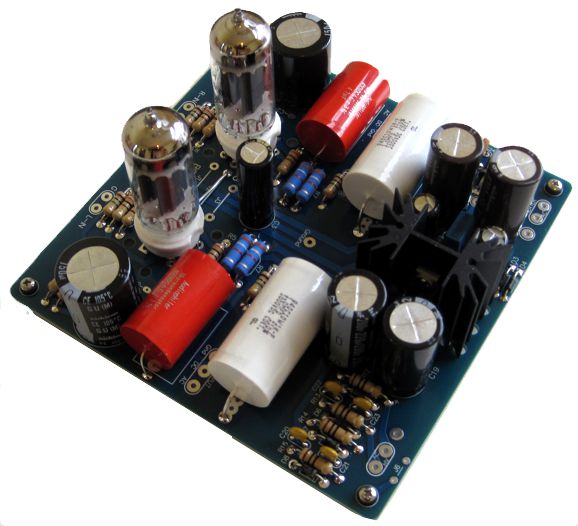
I blew the dust off this little cutie, which is a unity-gain buffer that holds its own bipolar, high-voltage power supply and a regulated heater power supply. I was able to fit the 6in by 6in PCB inside a small extruded enclosure made by Hammond along with an A3 Mini stepped attenuator. Since the Chromecast Audio puck puts out such a hot (i.e. big, large) signal, I had no fear that the unity-gain would be a problem. The great thing about this setup is that I can can listen to the Chromecast Audio device straight, and then quickly run its output signal through the ACF-2, which I proceeded to do posthaste, i. e. with great immediacy. So, how did it sound? Far, far better than I had expected, which troubled me greatly. I have been listening to the Chromecast Audio device/puck "naked" for months now. (Puck naked, not buck naked, just in case you got the wrong idea.) When I first got it, I had tried it with an Aikido line-stage amplifier, but the small puck’s hot output required no extra gain. Thus, I have hooked my tube power amplifiers directly to the Chromecast Audio puck. The naked sound is clean and crisp, but the sound after traveling through the ACF-2 tube circuit sounds less mechanical, more palpable, and far more emotionally engaging.
How is this possible? Yes, I know that I have been a tube fan for over four decades and that I design and write about tube-based harmonic-enhancement circuits, but it still troubles me that we can get better sound with tubes after the fact, as it were, as the Chromecast Audio puck’s output signal is ready to go, requiring no amplification. Why does it bother me? Well, if nothing else, it seem so contrary to the rule that less is more, and so against the principal of entropy, i.e. the gradual and eventual decline into disorder. Yet, my ears and soul prefer hearing the sound after it has flowed through tube circuitry, just as my eyes prefer seeing the world through my eyeglasses. I have a similar problem with passive line stages, as my mind tells me that I should prefer its sound to the sound after it has passed through active electronics, but my ears tell me a different story. One thought was that the $$ NOS Siemens 6DJ8/E88CC tubes with gold pins were lending a psychological experiential overlay to my listening. Something like this happened about 30 years ago when I was visiting a friend and I spotted an interesting artwork on her mantle. I picked it up and looked it over, admiring the skill needed to create such delicate features in the carved ivory. She told me that she was foolish for leaving it there on display, but she loved seeing it daily, although it really belonged in a bank safety deposit box, as it was almost 200 years old and worth close to $100,000. Suddenly, my eyes blurred, my hands trembled. I felt the fear of my dropping it or my damaging it sweep over me, as did a sweeping upgraded evaluation of its delicacy and merit. Had she said that she was embarrassed for liking such obvious kitsch, and that she had bought it for $2 at a flea market, would I have devalued it accordingly? Probably, sad to say. I replaced the NOS jewels with a pair of new JJ 6DJ8 tubes. Okay, I could quibble over subtleties, but the JJ tubes sounded far closer to the NOS tubes than apart. After five minutes, I forgot about the tubes and I immersed myself in the music. (I remember reading that a famed Brit audio critic exclusively listened to country-western music when evaluating audio gear, as he hated country-western music, so there was no chance that the artistry would overwhelm the purely technical. I tried his approach, but I found myself just liking the country-western music all the more. I admit it: I like country-western music, particularly the old, non-slick, non-crossover country-western music that twanged and plucked away in a doleful manner. By the way, I live not very far south from the Wyoming border. It turns out that there is a difference between Colorado cowboys and Wyoming cowboys: in Wyoming, the cowboys stuff their pant legs into their boots; in Colorado, over their boots.)
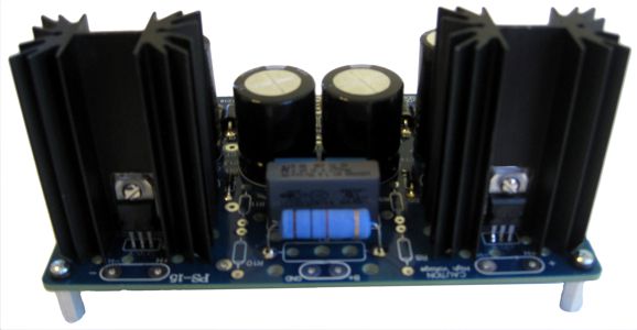
Still, my original idea needs testing, as feeding the Chromecast Audio puck from a linear-regulated 5Vdc might make a big difference. I remember reading that the line-driver IC used in the puck, the DRV632, demanded a clean power-supply voltage, which the PS-15 could supply along with the regulated 12Vdc for the tube heaters. My plan was to wire up the primary of a toroid transformer for 230Vac use but, instead, plug it into my 120Vac wall outlet, so the dual secondaries would drop from yielding 12Vac to 6Vac.
This would allow one to be rectified and regulated down to 5Vdc, while the second 6vac winding would feed a voltage-doubler rectifier arrangement that would feed the 12Vdc regulator.
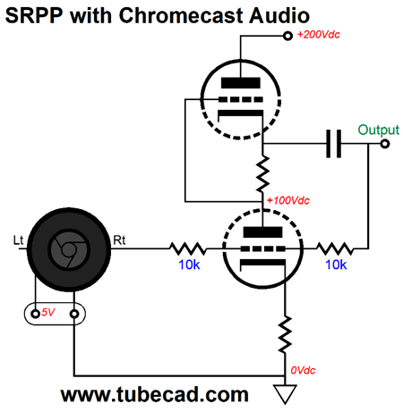
My original plan did not include adding an attenuator, but after using my little ACF-2 with an attenuator, I don’t want to be without it. I like the idea of using analog attenuation over digital. (See post 355 for more details about resolution loss and digital attenuation.) By the way, one reader asked why I did not include any SRPP circuits for use with the Chromecast Audio puck. To be frank, I don’t see the SRPP adding anything special to the Chromecast Audio puck, as the device already puts out a hot signal, so more gain is the last thing we need—unless, of course, you plan on driving a power buffer that requires tens of volts of input signal. On the other hand, the following SRPP circuit might prove best for some.
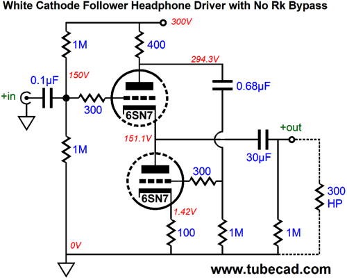
The SRPP is configured as a plate follower (AKA, anode follower), with unity-gain output. Mind you, the signal phase gets inverted, which might be what your want. In contrast , the White cathode follower would be a good match, as it happily could drive 300-ohm headphones.
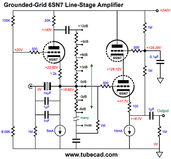
Another circuit that I meant to show was the following.
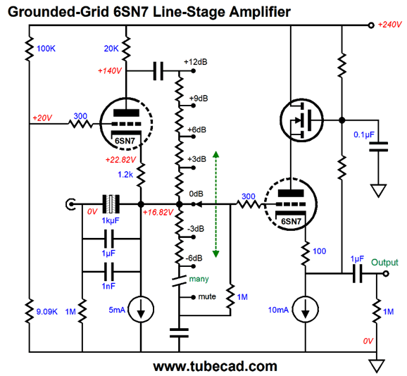
The idea behind this design is that if we need gain, we get gain; otherwise, we don't. The input impedance is about 4500 ohms, which the Chromecast Audio puck (and most DAC and CD players) can drive. The gain at the plate is 1:4, or +12dB. As we move down the stepped attenuator's posistions, we hit 0dB, where the grounded-grid amplifier no longer provides any gain, as we are tapping directly off the signal source. Then as we move through the steps, we finally end at a full mute. At each step, the cathode follower sees a steady DC voltage, but a varying input AC signal. The 100k & 9.09k two-resistor voltage divider provides the Aikido mojo of nulling the power-supply noise from the grounded-grid amplifier's output and give the 5mA constant-current source more voltage to work within. The totem-pole cathode follower helps improve the bottom triode's PSRR at its output. We can replace the top triode with either a transistor or MOSFET, as shown below.
Bear in mind that a rotary switch will be needed, not a potentiometer. Also note that the grounded-grid amplifier does not invert its input signal's phase, so no aberration will be heard as you move in and out of amplification.
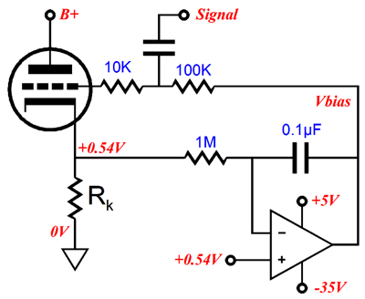
Auto-Bias Schemes While at the RMAF, I saw many push-pull tube power amplifiers that held auto-bias circuits. Far too many, in my view, as getting auto-bias right is easy with single-ended and class-A push-pull power amplifiers, but almost impossible with class-AB amplifiers, which 99% of all tube power amplifiers are. For example, many are using a DC servo circuit to set the auto-bias grid voltage.
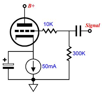
This circuit works fine within a single-ended amplifier of a class-A (real class-A) push-pull power amplifier. Within a class-AB amplifier, however, the 0.1µF capacitor in the DC servo feedback loop become charged up excessively, which forces the negative-bias voltage to fall. If the OpAmp's negative power-supply voltage is low enough in voltage, the OpAmp will end up turning off the output tubes. This seldom happens, however, as it takes a big negative grid voltage to turn off a KT88 or 300B (the EL84 on the other hand...). The second approach is to use a constant-current source that is bypassed by a large capacitor.
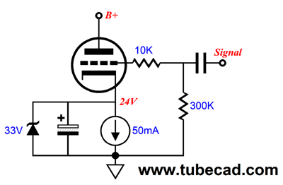
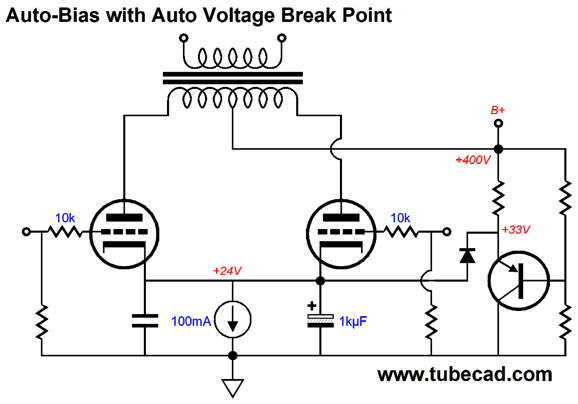
Once again, this circuit works fine within a single-ended amplifier of a class-A or a class-A push-pull power amplifier, but not within a class-AB amplifier. If the output stage were sufficiently overdriven, the large-valued electrolytic capacitor could charge up to voltage big enough to turn off the tubes after the crescendo ends. Usually, this does not happen, as few can bear the distortion resulting from being overdriven to such an extent. The easy workaround is to add a zener diode, whose break voltage is a few volts greater than the expected cathode voltage.
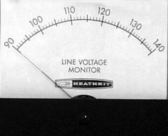
Picking the right zener voltage is where art enters the design. One problem we might face is varying wall voltages. I used to live in the Scotts Valley, California, where my nominally 117Vac wall voltage ran a constant hot 122Vac. (I own a Heathkit wall-voltage meter and I would look at it every 20 minutes.)
In contrast, I knew this audiophile who lived in a Victorian apartment building in San Francisco, whose nominally 117Vac wall voltage ran a cool and inconstant 107Vac; the voltage would climb and fall depending on his neighbor's use microwave ovens and vacuum cleaners. This meant that a power amplifier with a nominally 400Vdc B+ voltage ran a constant 417Vdc at my place, but an inconsistent 366Vdc at his place. This was a difference of over 50V. Thus, one workaround might be to forgo the zener and use a PNP transistor instead.
As the wall voltage climbs up and fall down, so does the cathode voltage and the break voltage. If the cathode voltage ever climbs up enough to forward bias the diode, the PNP transistor halts the upward climb. Returning to the DC servo auto-bias scheme, the easy workaround is to set a floor to how low the grid-bias voltage can fall, which can be as easy as limiting the OpAmp's negative power-supply rail voltage. Some use a PNP after the OpAmp, which will require some extra provision to limit the bias-voltage fall. A quick recap: the Brook amplifier auto-bias scheme that offers a high idle current that falls with crescendos is worth keeping in a class-AB push-pull amplifier. But can we take this idea further?
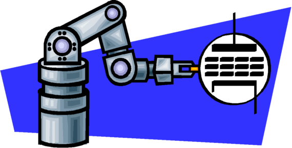
Shifting Vg and B+ Voltages In other words, at idle or when playing music softly, the idle current would run hot, while the B+ voltage would run cool. With loud music playback, the idle current would fall and the B+ voltage would climb, allowing more power output. Here is the design that I came up with:
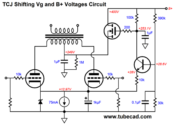
As the cathode voltage climbs up, so, too, does the B+ voltage. The constant-current source, which would be made from an LM317, sets the idle current. But as the music grows in volume, the large-valued bypass capacitor charges up, decreasing the idle current due to the higher cathode voltage. This increase in cathode voltage is them amplified by the NPN transistor, which is configured in a common-base amplifier topology, which controls the MOSFET's gate voltage, resulting in a higher B+ voltage. The zener voltage is not specified, but a good guess would be 20V, maybe a tad less. Mind you, the above schematic is a bit raw, as I lifted from my SPICE simulations, which were more of a proof of concept than a finished design. For example, the 400V raw B+ voltage is crazy hot for an EL84 tube. Note that at startup, when the output tubes are still cold and not conducting, the B+ voltage applied to their plates will be low, far lower than at idle, say a little over 100V, which can only help extend their life spans. The same circuit could be used with different output tubes, as long as suitable adjustments were made. For example, using 6L6 or KT88 tubes would require using an LM317-HV, whose higher voltage rating will be needed; with 300B output tubes, a TL783 would be the safer choice. Of course, a constant-current source made from discrete devices could be used instead of the three-pin voltage regulators. Okay, that's great, John, but I would rather drink fine wine from a paper cup than use an electrolytic capacitor at the cathodes. Well, I understand your fretting, so here is an alternative version that uses a shifting negative-bias voltage instead.
The common-base amplifier has been replaced by a common-emitter amplifier, but the principle is the same: as the negative-bias voltage falls, decreasing the idle current, the B+ voltage rises, allowing more power output. By the way, in both versions the B+ voltage gets purged of much of the power-supply ripple by the MOSFET and the relatively clean gate voltage it sees.
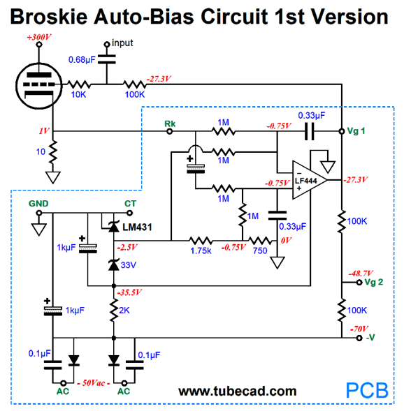
Non-Shifting Auto-Bias Circuits
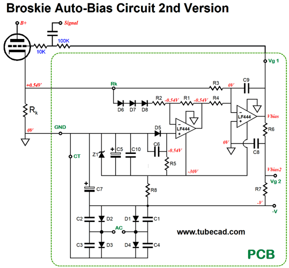
The idea behind this circuit is that since we know that the DC servo's integrator capacitor will charge up with loud music playback, we need only also charge up the voltage reference's capacitor equally. This scheme works, but not perfectly. I discovered that the large-valued electrolytic capacitor was the problem. I then came up with my second version, a few years later, which did away with this capacitor.
Diodes D7 through D8 only conduct when the tube moves beyond its class-A window of operation, which prevents capacitor C9 from becoming over charged. Two Vg outputs are offered. If EL34 or EL84 tubes are used, then the Vg1 one is used, but if KT88 or 300B tubes are used, we would use Vg2, which offers lower grid voltage. Clever, no? Just imagine the trouble I could cause if I were a patent lawyer.
//JRB
If you enjoyed reading this post from me, then you might consider becoming one of my patrons at Patreon.com.
User Guides for GlassWare Software
For those of you who still have old computers running Windows XP (32-bit) or any other Windows 32-bit OS, I have setup the download availability of my old old standards: Tube CAD, SE Amp CAD, and Audio Gadgets. The downloads are at the GlassWare-Yahoo store and the price is only $9.95 for each program. http://glass-ware.stores.yahoo.net/adsoffromgla.html So many have asked that I had to do it. WARNING: THESE THREE PROGRAMS WILL NOT RUN UNDER VISTA 64-Bit or WINDOWS 7 & 8 or any other 64-bit OS. I do plan on remaking all of these programs into 64-bit versions, but it will be a huge ordeal, as programming requires vast chunks of noise-free time, something very rare with children running about. Ideally, I would love to come out with versions that run on iPads and Android-OS tablets. //JRB |
E-mail from GlassWare Customers
High-quality, double-sided, extra thick, 2-oz traces, plated-through holes, dual sets of resistor pads and pads for two coupling capacitors. Stereo and mono, octal and 9-pin printed circuit boards available.
http://glass-ware.stores.yahoo.net/ Support the Tube CAD Journal & get an extremely powerful push-pull tube-amplifier simulator for TCJ Push-Pull Calculator
TCJ PPC Version 2 Improvements Rebuilt simulation engine *User definable
Download or CD ROM For more information, please visit our Web site : To purchase, please visit our Yahoo Store: |
|||


| www.tubecad.com Copyright © 1999-2017 GlassWare All Rights Reserved |