| John Broskie's Guide to Tube Circuit Analysis & Design |
|
15 March 2017 Post 374
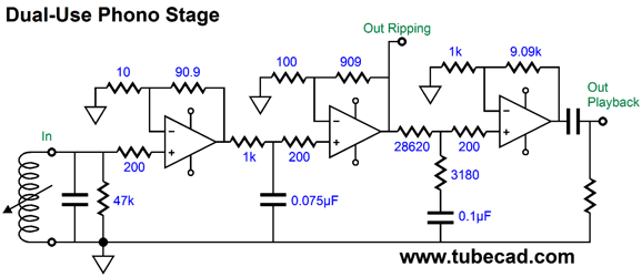
More Phono Preamps for Ripping In short, I am not sure which way is best. I do not, however, want to build a secondary phono preamp, preferring to own a dual use phono stage that offered two outputs: one for ripping and one for LP playback as a fully functional phono stage. With OpAmps, this would prove fairly easy to implement.
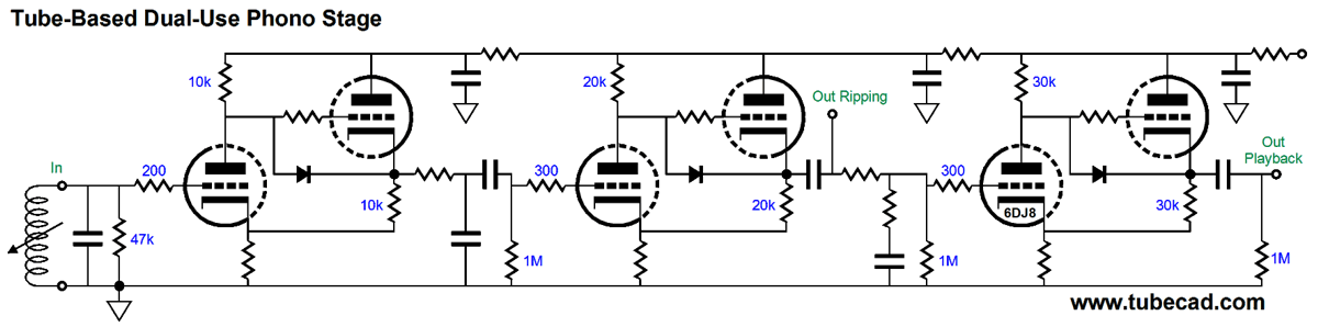
The above schematic shows three gain stages, each delivering +20dB of gain, in cascade. The LP ripping output comes after 40dB of gain and the imposition of the 75µS turnover frequency low-pass filter function, leaving the bottom half of the reverse RIAA EQ frequency tailoring is left for software. The LP-playback output gets the full RIAA EQ treatment and final gain of 40dB (20dB were lost in providing the passive bass boost from 50Hz to 500Hz). Making an all-tube version would prove a bit more difficult, due to the high voltages and the heater demands. Nonetheless, three CCDA gain stage in cascade can perform the same functionality as the OpAmp versions.
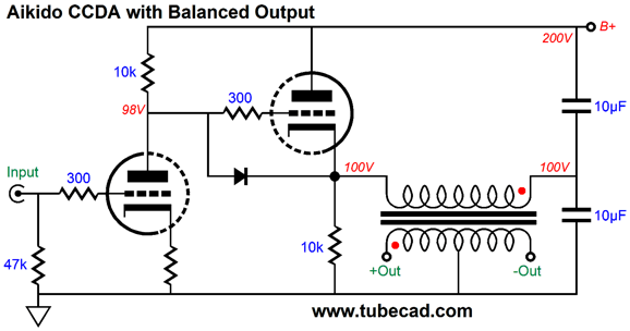
One schematic that I forgot to include in my last post is the following, which is both super simple and super effective.
The unbalanced input gets amplified and the output transformer provides the balanced output. (The output transformer can also provide signal gain, with step-up ratio.) The Aikido Mojo obtains from the the two 10µF power-supply capacitors. The CCDA's output offers a PSRR of -6dB. In other words, 50% of the B+ ripple will leak out of the CDDA's output. So, too, 50% of the B+ ripple will appear at the the two capacitor's connection to each other. Since the transformer is an intrinsically differential device, it will not "see" any B+ ripple signal differential across its primary, as an equal amount will develop across both of the primary's ends; thus, no B+ ripple can appear across its secondary. If we place a bypass capacitor across the input triode's cathode resistor, however, then the capacitor ratio must change, so that the output transformer's primary sees the same amount of B+ noise on each side of its winding. This circuit might just come in handy for LP ripping, as differential ADCs provide the best performance. But as no reverse RIAA equalization is provided, software must equalize the digital signal.
More Super-Triode
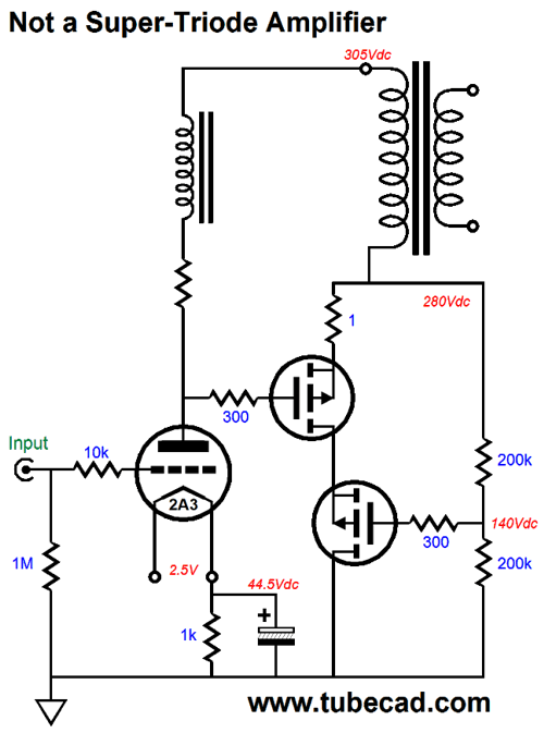
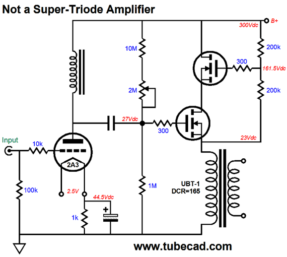
The 2A3 triode does not drive the loudspeaker, the two P-channel MOSFETs do. The 2A3 does, however, provide the needed signal amplification, but the 2A3 has no idea what the MOSFETs then do to this amplified signal. Note the inductive load for the 2A3, which delivers the constant-current operation we desire from the 2A3. (Inductors are magical devices. How so? The 2A3's plate can swing down and UP 150V, because of the choke, which allows us to use a B+ voltage of 305V.) The cascode MOSFETs are configured as source-followers, which means no gain, but low output impedance. The two 200k resistors ensure equal voltage splitting between MOSFETs. We can turn the output stage on its head, so that N-channel MOSFETs are used instead. Why? We can more readily find high-voltage N-channel MOSFETs. Moreover, the PSRR of this output stage is greatly improved over the previous version, as the transformer's primary is terminated into noise-free ground rather than the noise-filled B+ connection. (The inductive loading of the 2A3 shields the triode from the B+ noise, so the output at the 2A3's plate is noise-free.)
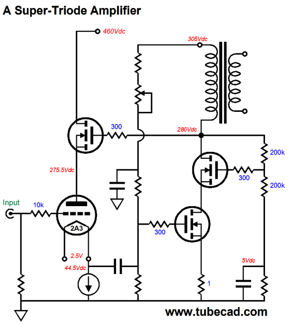
Note how we no longer need the resistor in series with the choke load for the 2A3, as the capacitor coupling between the 2A3 input stage and the MOSFET output stage uses its own means of establishing the correct bias voltage for the MOSFETs. (Effectively, we are using the output transformer's DCR as source resistor.) The following design is a super-triode amplifier, as the 2A3's cathode is loaded by a constant-current source, the N-channel MOSFET receives its input signal from the 2A3's cathode, and—most importantly—the output stage's output signal is relayed to the 2A3's plate via the MOSFET at's plate.
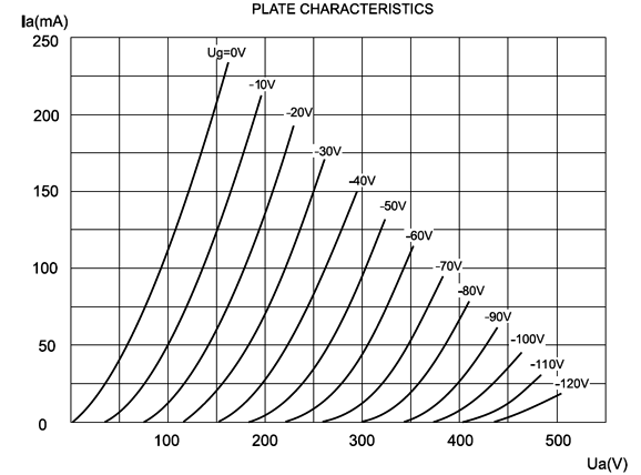
Note the absence of the inductor load for the 2A3; also note the two B+ voltages, 305V and 460V. Without the inductor, the 2A3 must connect to a higher voltage power-supply rail. The 2A3's plate can swing symmetrically down and up by about 170Vpk, before its grid goes positive relative to this cathode, as we can glean for the following set of plate curves of the JJ 2A3.
We start by locating the 50mA horizontal line and placing a point where cathode-to-plate voltage lies, which is equal to 275.5V minus 45.5V, or 231V. We then move to the left along the 50mA line until we hit the 0V grid-voltage curve (about 60V). Subtracting 60V from 231V equals 171V. Easy. The 2A3 does not drive the loudspeaker at all; instead, it drives the cascoded MOSFETs. The output transformer primary will see a +/-170V peak voltage swing. If all of this voltage swing could be delivered to an 8-ohm load, we would 1,800W of power. If only one tenth appeared across the 8-ohm load, due to a 10:1 winding ratio, then the power output would be 18W and the reflected primary impedance would be 10² against 8, or 800 ohms. Since we know the peak voltage swing, we can find the minimum idle current fort the MOSFET stage; i.e. 170V/800-ohms which equals 212.5mA.
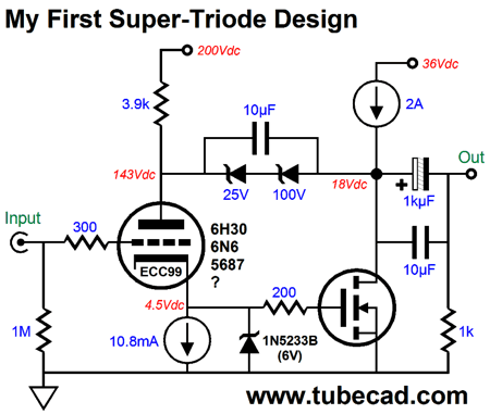
A little Super-Triode History
My first thought was that capacitor coupling between the triode's plate and MOSFET's drain would be needed, as would be capacitor coupling between the triode's cathode and the MOSFET's gate, which would include a DC servo. But the more I thought about it, I realized that the DC coupling throughout was possible and that the triode could perform its own DC servo function.
(In the schematic above, I list the ECC99 as the triode, but I certainly did not use this tube; instead, I remember using some beefy dual triode such as the 5687 or 6H30 or 6N6.) The idea behind this circuit is that the triode must conduct a constant current flow. If its grid voltage goes 1V positive, then its plate voltage must fall by its amplification factor (mu) or its cathode voltage must climb up by 1V/(mu + 1) or some blend of the two. Well, in the actual amplifier, if the cathode voltage climbs up even a small bit, the power MOSFET robustly fires up its current conduction, which will cause its drain voltage to swing down, which in turn will cause the triode's plate voltage to fall. The greater the power MOSFET's transconductance (gm), the closer this design comes to the super-triode ideal. The 2A constant-current source loads the MOSFET, making the output stage pure single-ended effort. The zeners establish a fixed DC voltage drop, which the 10µF bypass capacitor helps in passing AC signals. The triode's plate indirectly—via the zeners—sees the MOSFET's drain voltage, which should sit at half the output-stage's 36V B+ voltage, i.e. 18V. If the drain voltage goes higher, so, too, the triode's plate voltage; and thus so, too, the triode's cathode voltage, which will prompt the MOSFET to conduct more current, which will pull both its drain voltage and the triode's plate voltage down. By the way, a good question to ask is: Why didn't I post this circuit back then? First of all, only a small fraction of my circuits ever end up getting posted. I recently was about to throw away a piece of scrap paper, until I noted the interesting schematic I had drawn in one corner. Dang, it was provocative and I marveled at how I had forgotten that I drew it. Second, I had just received a gift from Philips (now NXP Semiconductors) of an evaluation board of their TDA8920B class-D stereo power amplifier. This was the first class-D that I enjoyed hearing—well, up to about 5kHz. I was so taken with this tiny amplifier that I stopped thinking about tube or hybrid amplifiers for a almost a month. (I had used a laboratory-grade regulated bipolar power supply that weighed over 100lbs; the TDA8920B didn't sound so lovely with a conventional power supply. In addition, I tried the class-D amplifier in the bridge/differential configuration and all the magic vanished.) Third, and last, I was still getting a lot of angry e-mail about dissing Bruce Rozenblit's patented OTL fix which made use of a zener in the failed attempt to equalize the top and bottom drive voltages in a totem-pole OTL output stage. The zener bridged the output to the plate of the cathode follower that drove the top output tube. Alas, this topology is only 1/mu as effective as it should be. Why? a triode's plate is 1/mu as effective as its grid in controlling the current flow through the triode. With a 6AS7, with a mu of 2, this means the plate 50% as effective; with a 6SN7, with a mu of 20, only 5% as effective. Wait a minute, John, the US Patent Office, which is entirely populated with latent Albert Einsteins, men and women for whom no design is too complex to be readily apprehended in its totality, has vouchsafed Rozenblit's solution. Therefore, no argument is possible. Yeah, sure. As a young man, one of my great pleasures was reading the reviews of recent speaker patents at the back of the Journal of the Audio Engineering Society, as the patented speaker designs were so often ludicrous that the ensuing review was as funny as a good New Yorker cartoon. My conclusion is that just as every mother's child is beautiful, every invention is patentable (that is susceptible of patent protection)—even those that are not so beautiful. Well, my fear was that posting this zener-filled super-triode design would seem to establish my acceptance of Bruce's patented solution, as this zener bridged the output to the triode's plate, and the triode seemed to be configured as a cathode follower. Thus, I was zener-phobic for a few years. It's been years since anyone has sent me an e-mail complaining of my failing to understand how the magic zener worked. Why the drop off of zener-OTL-patent boosters? My best guess is that SPICE has gone so mainstream that anyone who had the required skill and half an hour to kill could readily prove for himself that the drive signals were not equalized by the zener. (Now, if the zener attaches to the phase splitter instead, we do get equal drive signals. See this Tube CAD Journal Article.)
JC Morrison's Super-Triode Amplifier Update If you have a good signal-grade isolation transformer and an oscilloscope (or a battery-powered oscilloscope), you can take a look at the AC voltage entering your house. Your are likely to be disappointed, as the waveform is not a pristine sinewave, but a highly distorted one. The days of clean AC are long over, as light-dimmers, computers, and those dozens of switcher wall-wart power supplies have all made a mess of the clean sinewave. One workaround might be to use a flat-pack transformer, which places its two, three, or four windings on separate coil-forms, not atop one another as most other transformers do.
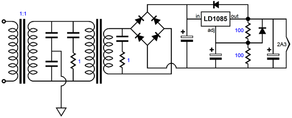
The result is far lower inter-winding capacitance. In addition, we could use the following circuit, which uses an isolation transformer.
This setup is quite effective in reducing RFI from leaking into the regulated DC output. The 1-ohm resistors are there to convert the RFI into a different from of energy, i.e. heat. Perhaps, rather than grounding the two series capacitors to the signal ground, we should use the house ground. Or, if we are too lazy, which I certainly am, we could simply replace the DC regulated filament power supply with a 6V motorcycle battery and a big power resistor to see if dirty DC is the cause of the problem. One remaining question to answer is, Why didn't the plate configuration present the same problem that the cathode configuration encountered? My guess is that if the following 2A3-based super-triode cathode follower were tried, it, too, would suffer from the dirty DC problem.
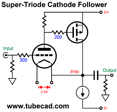
Why? The constant-current source load on the triode's plate allows more of the dirty DC to leak through, as it allows vastly more supercharging to obtain. In contrast, the following 2A3-based super-triode cathode follower uses a 100-ohm plate resistor, which only delivers a small portion of the potential supercharging.
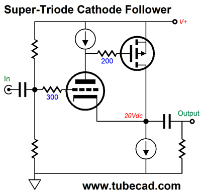
In other words, I am sure that the dirty DC problem occurs in both circuits, but as the CCS-based one offers so much more boosting from the P-channel MOSFET that the noise gets more amplification. A simple test would be to build both and see what happens. Speaking of super-triode cathode followers, another variation would be the following.
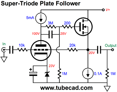
This variation uses a mono-polar power supply. By the way, do fight the urge to eliminate the coupling capacitor in the previous design, as at start-up, when the triode is still cold and not conducting, the constant-current source will throw the output to the negative power-supply rail voltage. Not good. While on the topic of followers, let's look at a super-triode plate follower.
The 3M resistor that shunts the internal coupling capacitor allows the triode to control the N-channel MOSFET's source voltage. The 10k and 20k feedback resistors set the gain to 2, or +6dB. This circuit does not require any Aikido mojo techniques, as it already would boast a fine PSRR. Before any reader is tempted to write me, asking if a power amplifier could be made from this topology, the answer is yes. I would up the triode's current flow to at least 10mA and I would give the MOSFET its own much-lower power supply voltage, say about 24V, with the MOSFEZT and it constant-current-source load each seeing 12V.
//JRB
If you have been reading my posts, you know that my lifetime goal is reaching post number one thousand. I have 626 more to go. My second goal is to gather 1,000 patrons. I have 967 patrons to go. If I were a betting-man, I would place my bet on reaching the 1,000-patron goal first, as I have a hard time believing that I have already posted 371 times. How is that possible? I would never have bet on that happening. If you enjoyed reading this post from me, then you might consider becoming one of my patrons at Patreon.com.
Next Time
User Guides for GlassWare Software
For those of you who still have old computers running Windows XP (32-bit) or any other Windows 32-bit OS, I have setup the download availability of my old old standards: Tube CAD, SE Amp CAD, and Audio Gadgets. The downloads are at the GlassWare-Yahoo store and the price is only $9.95 for each program. http://glass-ware.stores.yahoo.net/adsoffromgla.html So many have asked that I had to do it. WARNING: THESE THREE PROGRAMS WILL NOT RUN UNDER VISTA 64-Bit or WINDOWS 7 & 8 or any other 64-bit OS. I do plan on remaking all of these programs into 64-bit versions, but it will be a huge ordeal, as programming requires vast chunks of noise-free time, something very rare with children running about. Ideally, I would love to come out with versions that run on iPads and Android-OS tablets.
//JRB
|
|
Kit User Guide PDFs
Only $12.95 TCJ My-Stock DB
Version 2 Improvements *User definable Download for www.glass-ware.com |
||


| www.tubecad.com Copyright © 1999-2017 GlassWare All Rights Reserved |