| John Broskie's Guide to Tube Circuit Analysis & Design |
19 April 2016 Retrograde Cascode
Inverted Cascode
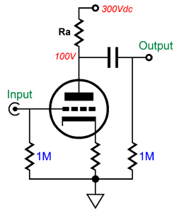
A grounded-cathode amplifier's gain can never exceed its amplification factor (its mu). Why not? Answer: the triode's own plate resistance shunts its transconductance. Thus, any plate-load resistance is always in parallel with the triode's rp, which limits the triode's potential signal gain and mitigates the triode's transconductance. In other words, even if the triode attaches to a constant-current source as its plate-load resistance, the maximum gain realizable will equal its mu. In fact, a triode's amplification factor (mu) is derived from multiplying its transconductance (gm) by its plate resistance (rp): mu = gm · rp Thus, a constant-current source's near-infinte impedance in parallel with rp equals rp. The highest-mu triode that is commonly available is the 12AX7, which boasts a mu of 100. Moreover, whatever signal gain is achieved by the grounded-cathode amplifier will generate Miller-effect capacitance, which limits the grounded-cathode amplifier's high-frequency bandwidth. In other words, the high gain we desired effectively amplifies the triode's grid-to-plate capacitance, which limits the high-frequency bandwidth. The Miller-effect capacitance is equal to the grid-to-plate capacitance against the sum of the gain + 1.
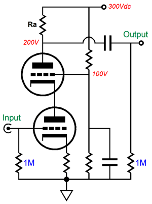
In contrast, a triode-based cascode preserves the bottom triode's transconductance and it sidesteps the creation of Miller-effect capacitance, thereby greatly extending high-frequency bandwidth. The cascode's What is simple enough: a cascode circuit comprises two active devices in series that share a common current path to the power supply, creating a simple two-stage amplifier. These two devices can be triodes, pentodes, FETs, MOSFETs, or transistors; and they can be a mix of these devices.
The cascode's When was 1939, when Hickman and Hunt introduced and detailed the cascode topology in their paper, "On Electronic Voltage Stabilizers," in the Review of Scientific Instruments, January 1939, pp. 6-21 (page 16). The name Cascode is said to be a contraction of "CASCading triodes with the gain of a pentode and the low-noise of a triODE;" I have also seen it described as a contraction of "CASCading triodes having similar characteristics to a pentODE." What Hickman and Hunt, no doubt, had in mind was that we could treat (or view) the two triodes within a single tube envelope, such as the two within the 6DJ8 and 6SN7 and 12AU7, as being configurable as a single device worthy of its own device name ending in "ode," much like the diode, triode, tetrode, pentode, heptode, and octode.
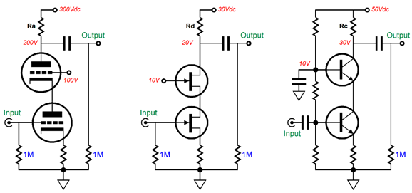
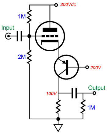
In the decades that immediately followed its creation, rarely was the tube-based cascode used in audio applications; instead, its use was restricted to power-supply and radio work. Then in the 1980s, the tube-based cascode was rediscovered and used in tube-based, high-end audio products, often tube phono stages. The cascode's How is actually quite simple. The top active device (triode or FET or transistor) functions as a DC buffer, fixing the bottom triode's cathode-to-plate (or emitter-to-collector or source-to-drain) voltage to a set value, thereby allowing it to retain all of its transconductance. In addition, the fixed plate (or drain or collector) voltage prevents the generation of any Miller-effect capacitance. The load resistor sees a varying current flow, which develops a varying outputvoltage. Since the triode's transconductance is held constant, the larger the resistance, the greater the signal gain, which can easily exceed that of the triode's amplification factor. Effectively, the cascode gain is equal to transconductance against load resistance. For example, a 6DJ8 is high-gm triode that can easily realize a gain of 200 in a cascode circuit; a 12AU7, low-gm triode, a gain of 40. In other words, unlike a grounded-cathode amplifier, which requires a high-mu triode to achieve high gain, a cascode requires a high-gm triode. For example, a 5687 is a much better choice than a 12AX7 in a cascode, if high-gain is your goal. In an inverted cascode, the top active device sees the input signal, while the bottom device sees the fixed reference voltage; and the inverted cascode's load resistance attaches below the bottom device, not above the top device. Since no one makes a P-version of the triode, we must use either a P-channel version of a FET or MOSFET or a PNP bipolar transistor as the bottom active device. Below, we see a triode-transistor hybrid inverted cascode.
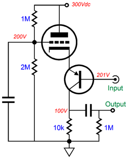
The triode receives the input signal and the PNP transistor sees a fixed reference voltage. The collector resistor translates the varying current flow (induced by the triode) into varying output voltage. Note that this load resistor could terminate into a negative power-supply rail rather than the ground. The PNP transistor, which could be either a MJE350 or MJE15033 or MJE5852G, functions as voltage regulator, as its emitter presents a fixed DC voltage and a low output impedance. Thus, the triode's transconductance remains intact, as it sees a fixed cathode-to-plate voltage. What if the roles were reversed in this circuit, so the triode saw the fixed DC reference voltage and the PNP transistor received the input signal? Two results: less gain and no cascode.
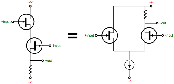
The triode's output impedance at its cathode is much higher than the transistor's emitter, which will subtract from the transistor's gm, as the cathode impedance effectively becomes an emitter resistor, a needlessly expensive emitter resistor. Furthermore, this circuit would no longer be a cascode, as the transistor would not work under a fixed emitter-to-collector voltage, as its collector would swing up and down with the output signal, which would create Miller-effect capacitance. The essence of a true cascode is that the varying current the input device produces flows through another active device before meeting the load resistance. The circuit shown above is just an odd-looking grounded-emitter amplifier. Another circuit topology that looks like a cascode but isn't is the bastode, which is a vertical differential amplifier. (See blog number 294 for more information on the bastode topology.) Two inputs, one output, much like the conventional horizontal differential amplifier shown on the right. The key disqualifier for being a cascode is that both active devices see an input signal.
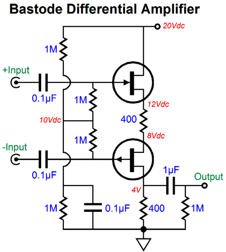
The following circuit is a FET-based bastode differential amplifier. If both inputs see the same input signal, no signal will leave the output, as the differential amplifier only amplifies differences, while rejecting common signals.
If the bottom FET, the P-channel FET, sees no AC signal but a fixed DC voltage, then the circuit would be a cascode, however.
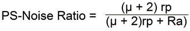
Inverted-Cascode Advantages & Disadvantages Wait a minute, John, I remember reading that the cascode offered low-noise performance. It does, but at radio frequencies, not audio frequencies. At radio frequencies, low-frequency noise, such as hum and microphonics, does not count. Here is the formula for the amount of power-supply noise that will leak out of the cascode's output.
This formula assumes a bypassed cathode resistor (or negative-grid bias). If Rk is unbypassed, then the following formula is needed.
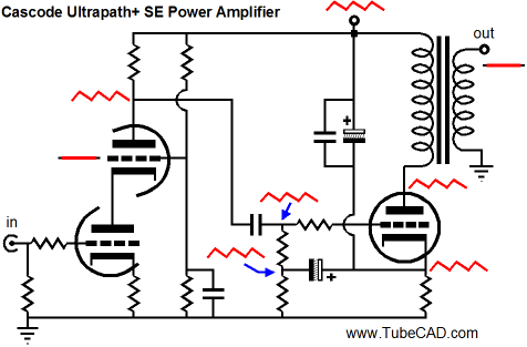
To convert the result into dB we take the log of the result and then multiply it by 20. Is this the end of the world? No. If the B+ voltage is regulated or well filtered, then there might not be much power-supply noise to leak. In addition, a nearly nonexistent PSRR is sometimes a feature. What!? In some circuits we purposely want all the power-supply noise to leak into the output signal. One example is the Ultra-path single-ended amplifier that designed in back in blog number 147.
In this circuit the output tube, output transformer are referenced to the B+ connection, not ground, due to the Ultra-Path configuration, so the cascode's nearly nonexistent PSRR is definitely a feature. In contrast, an Aikido stage's exemplary PSRR would create a noisier output at the speaker, paradoxically enough. Remember how in rough seas only the drunk can walk upright across the ship's deck.
Inverted-Cascode Applications
And here is one from 2001.
In both circuits, the inverted cascode's poor PSRR is put to good use. And in my three posts on tube-based OpAmps, we find many examples of inverted cascodes. Here is one example from blog number 206.
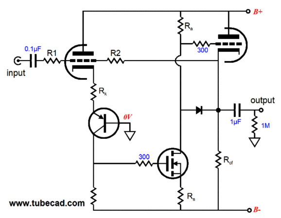
This design uses three technologies: tube, transistor, and MOSFET. An interesting design, but I would draw it differently today. (By the way, the N-channel MOSFET could be replaced by another triode.) Okay, rather than list many more old designs, let's see something new: an inverted cascode hybrid amplifier.
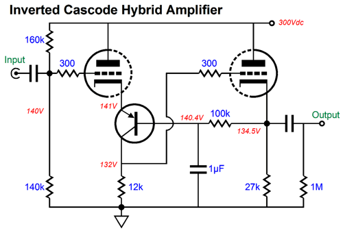
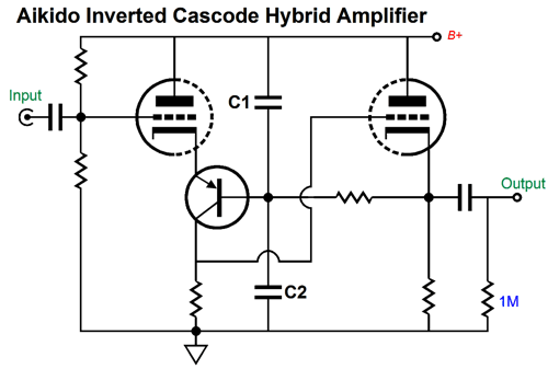
The left triode accepts the input signal, while the right triode functions as a cathode follower. The PNP transistor locks the input triode's cathode to a DC voltage, but lets all the variation in current flow to pass onto the 12k collector resistor. Here the inverted cascode's poor PSRR is sidestepped by the 12k load resistor terminating into ground, not the B+ connection. Nonetheless, the PSRR is not great, as the input triode's plate sees 100% of the power-supply noise, which will be amplified if the load resistor's resistance is greater than the input triode's rp. In other words, the triode's plate resistance sees the power-supply noise and generates a varying current flow as a result. Is there a workaround? Did you really need to ask? Of course there is, the Aikido inverted cascode amplifier.
By purposely injecting a small portion of power-supply noise into the PNP transistor's base we can null the power-supply noise at the output. Capacitors C1 and C2 define an AC voltage divider. What should the ratio be between capacitors C1 & C2? Capacitor C2 should be mu times bigger in value than C1. This ratio will ensure that the cathode see 1/(mu + 1) amount of power-supply noise which will cancel the 1/rp amount of current variation caused by the triode's rp, as the cathode is mu + 1 times more effective in controlling plate current than the palate is.
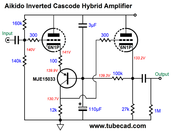
(Oh-oh, I see that I left off the 300V B+ voltage.) The signal gain for the above circuit comes in at about 36 (+31dB). Both the output impedance and distortion are low. If we replace the 12k load resistor with a 20k resistor, we get more gain and less current flow through the input triode. If the replacement resistor is lower in value, then less gain and more current flow will result. What about the cathode follower? It is rather immune to DC shifts, in spite of the changes in load resistance for the input stage. (The secret behind this circuit's magic trick is the 100k resistor. A transistor's base must draw some current, which in turn must flow through this resistor, so a voltage drop must develop across the 100k resistor. In this example, about 6V of voltage drop.) How would I use this circuit? Here is the answer.
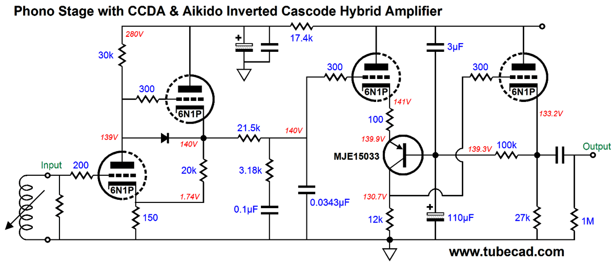
Click on schematic to see larger version
(Once again, I see that I left off the 300V B+ voltage; sorry.) Amazingly enough, this tube-based phono preamp only contains one coupling capacitor. Many fear coupling capacitors; but do they fear them more than they fear bipolar transistors? Of course, the PNP transistor could be replaced by a high-voltage MOSFET. And of course, if a different triode were used, then the ratio between capacitors C1 & C2 would have to be altered. Speaking of tubes, the 6N1P is a Russian tube that is equivalent to the Chinese 6N1 and roughly equivalent to the American 6BQ7A. This tube is both excellent and cheap, which is rare theses days. By the way, the one to buy is the 6N1P-EV, which is known for its low noise characteristics. This tube is not a 6DJ8/6922 replacement, contrary to what you might have read elsewhere. Let me repeat myself: the 6N1P is not a 6DJ8, 6922, 7308, ECC88 drop in replacement. It differs in mu, gm, rp, and heater current draw. Furthermore, one key difference a designer quickly finds is that it requires a higher plate voltage than the 6DJ8 type, because of its lower perveance, to establish the same current flow. This phono stage's total gain is about +40dB and with some tweaking, much more could be squeezed out of it by using more positive feedback in the first stage and a higher value load resistor in the inverted-cascode stage. If we used a 47k resistor instead of the 12k resistor, the gain from the inverted cascode stage goes up to 73 (+37dB). This circuit is what I wanted to begin with; but I knew that it would prove a head-scratcher, so it appears at the end. As T. S. Eliot put it it so nicely in Little Gidding, the fourth and final poem of Eliot's grand poem, Four Quartets.
Next Time
User Guides for GlassWare Software Since I am still getting e-mail asking how to buy these GlassWare software programs:
For those of you who still have old computers running Windows XP (32-bit) or any other Windows 32-bit OS, I have setup the download availability of my old old standards: Tube CAD, SE Amp CAD, and Audio Gadgets. The downloads are at the GlassWare-Yahoo store and the price is only $9.95 for each program. http://glass-ware.stores.yahoo.net/adsoffromgla.html So many have asked that I had to do it. WARNING: THESE THREE PROGRAMS WILL NOT RUN UNDER VISTA 64-Bit or WINDOWS 7 & 8 or any other 64-bit OS. One day, I do plan on remaking all of these programs into 64-bit versions, but it will be a huge ordeal, as programming requires vast chunks of noise-free time, something very rare with children running about. Ideally, I would love to come out with versions that run on iPads and Android-OS tablets.
//JRB |
Kit User Guide PDFs
And
High-quality, double-sided, extra thick, 2-oz traces, plated-through holes, dual sets of resistor pads and pads for two coupling capacitors. Stereo and mono, octal and 9-pin printed circuit boards available.
Designed by John Broskie & Made in USA Aikido PCBs for as little as $24 http://glass-ware.stores.yahoo.net/
The Tube CAD Journal's first companion program, TCJ Filter Design lets you design a filter or crossover (passive, OpAmp or tube) without having to check out thick textbooks from the library and without having to breakout the scientific calculator. This program's goal is to provide a quick and easy display not only of the frequency response, but also of the resistor and capacitor values for a passive and active filters and crossovers. TCJ Filter Design is easy to use, but not lightweight, holding over 60 different filter topologies and up to four filter alignments: While the program's main concern is active filters, solid-state and tube, it also does passive filters. In fact, it can be used to calculate passive crossovers for use with speakers by entering 8 ohms as the terminating resistance. Click on the image below to see the full screen capture.
Tube crossovers are a major part of this program; both buffered and un-buffered tube based filters along with mono-polar and bipolar power supply topologies are covered. Available on a CD-ROM and a downloadable version (4 Megabytes). |
||


| www.tubecad.com Copyright © 1999-2016 GlassWare All Rights Reserved |