| John Broskie's Guide to Tube Circuit Analysis & Design |
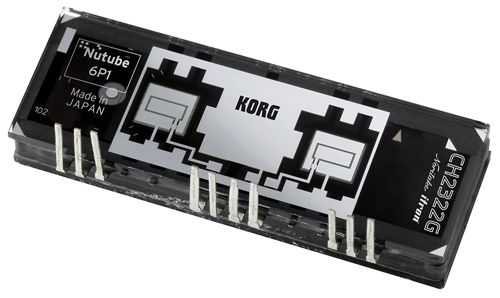
31 Januaray 2015 New Tube: Nutube 6P1
Back to the Future: Nutube 6P1 Imagine if the vacuum tube had never been invented, that we all grew up with FETs and transistors, and that just now some clever research scientist figured out how to make a vacuum-tube triode. Would it look anything like a 12AX7? I doubt it. Instead, it would look very much like the 6P1, compact and precise.
Even More
Even More Circlotron Circuits
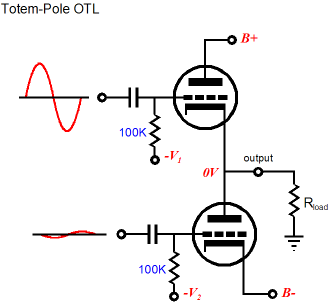
We can build totem-pole output stages with identical devices, either tube-based or transistor-based or MOSFET-based, but then we face the problem of delivering asymmetrical drive signals to the output devices.
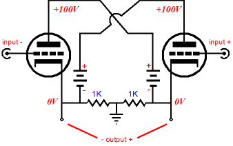
In addition, feedback must be used in creating the asymmetrical drive signals or the output impedances from the two output devices will not match each other. For example, in the above circuit, the top triode functions as a cathode follower, which exhibits a low output impedance; in contrast, the bottom triode functions as a grounded-cathode amplifier, which presents a high output impedance. Feedback from the output to the bottom triode creates a cathode-follower-like performance from the bottom tube. Well, if the Circlotron output stage offers so great an advantage, why don't solid-state amplifiers use it? A few do, but not many. Why not? We can amend Nietzsche's quip that
(#74 from his book, Human, All Too Human) with
Two floating power supplies are almost twice as expensive as a single, grounded bipolar power supply, and much cheaper than the four floating power supplies needed for a stereo Circlotron power amplifier. Well, if we bite our wallet and pay the extra expense that a Circlotron output stage demands, will we have arrived at perfection? No. True enough that we have made a move in the right direction, but we do not necessarily arrive? Why not? Few are willing to run their Circlotron output stages, in spite of what their ad copy says, in true, honest-to-God class-A. Why not? Heat. Lots and lots of heat. Moreover, we will need huge arrays of output tubes (or transistors) and massive power transformers and heavy heatsinks and strong back to the lift the amplifier. In a world that is rapidly going class-D, class-A is a hard sell to make. (See blog number 284 for more information on class-A operation.) Thus, 99.999% of power amplifiers run in class-AB, which offers less distortion than class-B and less wasted heat dissipation than class-A. In other words, a compromise.
Well, couldn't a class-AB, push-pull, power amplifier that used two perfectly matched output devices present the same low distortion of a class-A amplifier? No, sadly. Why not? Imagine not only perfectly matched output devices, but perfectly linear output devices, devices so linear that they made rulers look bent out of shape.
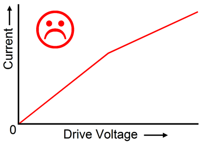
Yet these perfectly-linear devices, when paired up and placed within a class-AB output stage, must distort. In the class-A range of operation, the two devices work effectively in parallel, offering half of the output impedance and twice the transconductance of a single device. Once the output leaves class-A, however, and moves into class-B, with only one output device conducting, the output impedance doubles and the transconductance halves. So, while these perfectly-linear output devices would perfectly suit a class-A power amplifier, they would be ill suited to a typical class-AB output stage. (I remember reading in an issue of an RCA internal magazine that triodes, like the 2A3 and RCA 50 were best suited to class-A, push-pull use; whereas pentodes, like the 6L6 and 6V6, were best suited to class-AB, push-pull use. Why? The triode were more linear, while the pentodes exhibited a varying transconductance, making them a better match class-AB, push-pull operation.) Effectively, while operating in class-A, the load appears twice as large in impedance, so an 8-ohm speaker appears as a 16-ohm load. How's that possible? Once one output device cuts off, the load is seen for what it really is, an 8-ohm load. Don't get this? Imagine a push-pull output stage that runs an idle current of 1A. Now, imagine an input voltage of +8V and a load resistance of 8 ohms. The top output device will increase its conductance to 1.5A, while the bottom device will decrease its to 0.5A, with the load seeing 1A of current flow, as 8V will develop across it. In other words, the +8V input signal only provoked a 500mA increase in current flow through the top device, which would imply a 16-ohm load resistance with a single output device. But in a push-pull output stage, the load sees the delta, the difference in conduction between the two output devices, so the 8-ohm load sees +500mA - -500mA, which equals 1A. Once the push-pull output stage leaves the class-A overlap of conduction, the load only sees the delta in the single conducting device, so the load impedance is no longer effectively doubled. In this example, when the output voltage exceeds 16V. For example, if we increase the input signal voltage from 16V to 24V, the output current will go from 2A to 3A, the 1A increase implying an 8-ohm load, not a 16-ohm one. This break in continuity creates a glitch in the otherwise smooth transition, resulting in gm-doubling distortion, or what it should be called, gm-halving distortion, as in the overlap region things are fine. Now, imagine that we could buy output devices that presented two transconductances, the first being exactly half of what the second is.
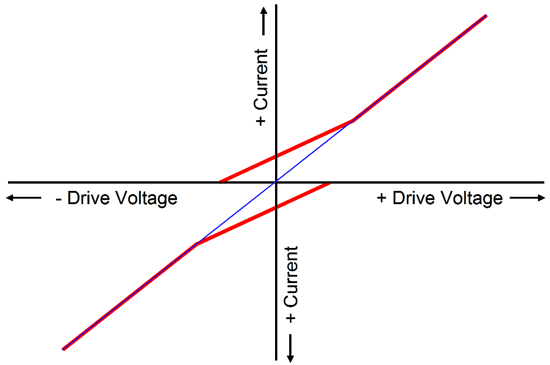
Such a device would make a terrible single-ended power amplifier. Much like a sharp jab in your sides from a pointed elbow, the twist in transconductance would thwack your ear.* On the other hand, such a device in a push-pull amplifier could—under the just right operating conditions—please and soothe your ears, just as your hand likes to run over new, taut, tidy, and smooth satin sheets. The procedure would be to set the idle current at exactly half of the transition current.
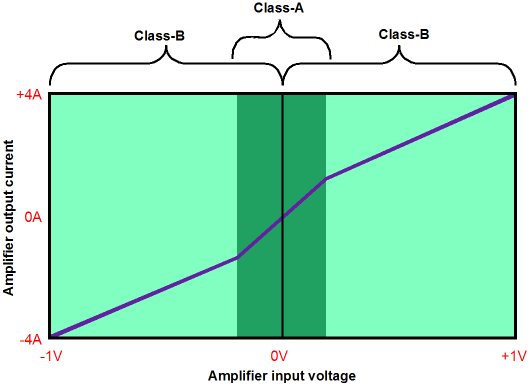
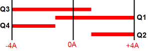
At exactly half of the transition current, the two output devices would perfectly overlap, creating a constant-gm transfer curve—or rather transfer line, as the line would not curve at all, as blue trace shows below.
What is happening is that in the class-A overlap of output-device conduction, the two half transconductances combine to equal second twice as large amount of transconductance. In other words, we still have gm doubling, but the doubling is against one half which results in unity. Mind you, if the output devices do exhibit two transconductances, but with the first one being less than the half of the second, then this trick will not work. Nor would the trick work if the second transconductance was less than the first transconductance.
Well, since we cannot buy these desirable output devices, being stuck with EL34, KT88, and BUZ901, IRF230, and MJ21194 output devices, what can we do? The usual approach is to employ gobs and gobs of negative feedback, so that the output is forced inline. Another far more subtle approach would be to apply a complementary pre-distorted drive signal, which would result in a linear transfer curve. Or, we could find a way to make the output stage behave as if it offered a constant transconductance.

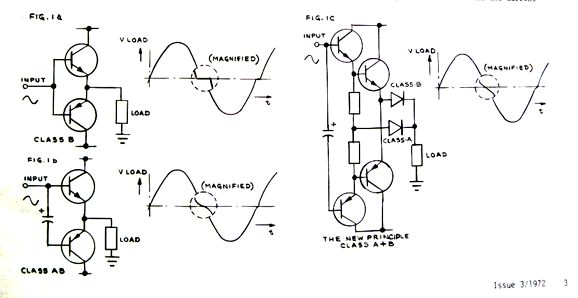
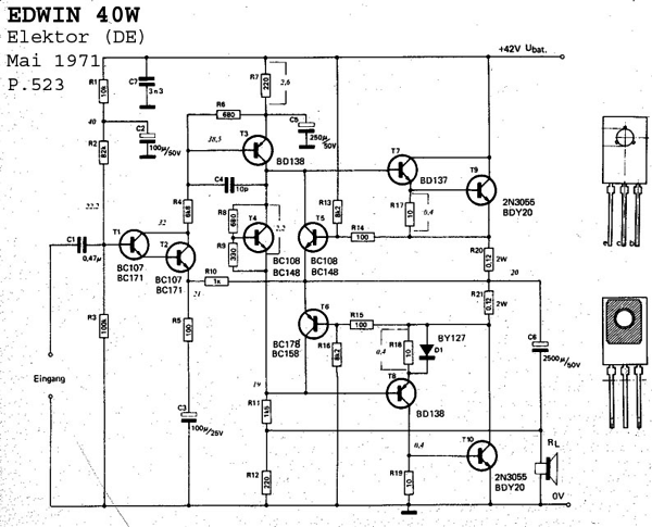
Class-AB + C Circlotron Amplifier Back in 2009, blog number 177, I described my attempts at creating a constant-gm output stage as class-AC. (A better name would be "class AB + C.") But before diving into the new circuits, I want to mention how I was haunted by a previous class AB + C design effort, but I could not remember where I saw it. I had been corresponding with Bob Cordell about gm-doubling and I wanted find the earlier article. Google was of no help, so I went hunting through my vast collection of old magazines. I knew that I had seen the article while in high school, so at least I could narrow my search to the years between 1970 and 1974. It took me a while to find it, but there it was: the Edwin class A+B amplifier from the 3rd issue of 1972 Audio Amateur.
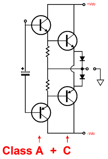
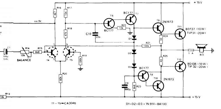
As I photo-scanned the page in the old magazine, I remembered my original discomfort with the illustration back in 1972. How so? I was convinced back then and I am today convinced that they got the schematic wrong, as the bottom diode is incorrectly placed. (I am sure that the Audio Amateur graphic artist had been given a sloppy schematic on a paper napkin and he (or she) couldn't see how the diodes must be connected.) The output stage drawing should have looked like this:
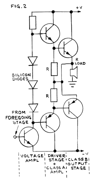
Now, the output stage makes sense—sort of; I believe the diodes were added only to stress the the point that the class-B transistors were not connected to the load at idle. In contrast, the two class-A transistors never cut off, while the two class-B only turn on as they are needed to fill in for the class-A pair. Actually, that put it the other way around, as Edwin's aim was to run two class-B output transistors (effectively class-C, wherein both devices are cut off at idle) and then use a pair of class-A transistors to fill in the void, wherein both of the class-B transistors didn't conduct. Therefore, his class-A transistors ran in very wimpy class-A mode, as were were only needed to fill in a small hole. As for the diodes, they are not needed and were not used in his actual amplifiers, example-1 and example-2. Here is another example from the Audio Amateur article.
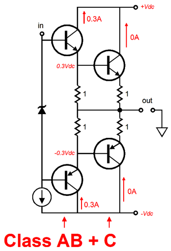
Such an arrangement will still create discontinuities in the transfer curve; two of them, in fact, two where each of the class-B transistors kick in, as these transistors do not offer the same output impedance that the class-A transistors do through their emitter resistors. On the other hand, if we run the first pair of transistors in class-AB, and set up the turn-on timing, the phasing of the class-C transistors perfectly, we can achieve a constant gm output stage. For example, with dead short to ground, this following output stage exhibits a constant gm (transconductance) of about 2A per input volt. With an 8-ohm load, the effective gm falls because of the 8-ohm load, which limits the current flow to about 1V/8.5-ohms. In other words, the higher the load impedance, the lower the effective gm of the output stage. With no load, changes in input voltage to not result in current-flow changes in the output stage. In terms of output impedance, the above output stage presents about 0.5 ohms of impedance. Of course, with a big dollop of negative feedback, the Zo will fall even lower. Still, 0.5 ohms isn't too bad, (a damping factor of 16) and is far lower than the typical tube amplifier's output impedance.
In the above circuit, the assumption is that the class-C transistors require a base-to-emitter voltage of 0.6V to turn on. Your mileage may vary, as they say. With MOSFETs, the turn-on voltage will be much higher, say between 1V to 5V; with vacuum tubes, the turn-on voltage will be negative, roughly equal to Vp/-mu. One key point to my efforts at a constant-gm output stage, besides the benefits that accrue from a constant gm, is that it allows us to run much heavier idle current through the class-AB devices, be they tubes, MOSFETs, or transistors. In contrast, a typical solid-state power amplifier that uses bipolar transistors usually run 40mA to 50mA at idle. The big problem is maintaining that trivial idle-current flow, as the transistor's base-to-emitter voltage drops as the transistor heats up, which requires elaborate and finicky circuitry to counter the change in transistors voltage effectively. In contrast, my 300mA of idle current (and the base voltages) is so fat that it can absorb a lot of slop and still work well, as the big 1-ohm emitter resistors are excellent current limiters that prevent the output stage from melting down, should the speaker cables short. But what of the high output impedance, resulting from such high-ohmage emitter resistors? If multiple pairing of class-AB+C transistors were used, as three pairs per channel, then 3-ohm emitter resistors could be used, which would definitely provide a wide safety margin. The following images are from my blog number 177 post, which you should read.
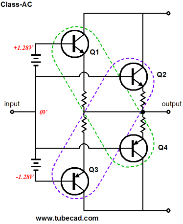
Transistors Q1 & Q3 draw current at idle, but transistors Q2 & Q4 do not. The net result is a constant gm, which effectively equals twice that of a single device.
Once again, a better name is class-AB + C, as transistors Q1 & Q3 do cutoff, so they do not run in class-A. Okay, John, this is all wonderful, but where are the dang tubes? There coming. Imagine if we replace the class-AB transistors with triodes, so the triodes will run in class-AB, while the remaining transistors will run in class-C.
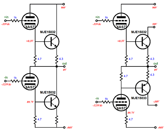
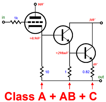
In other words, at idle and within the class-A envelope of current output, only the tubes will drive the speaker. But once we leave class-A, and one of the triodes ceases to conduct current, its counter-paired afterburner transistor fires up, drawing the make up current needed to yield a constant-gm output stage. With such an arrangement, we could build either of the following OTL output stages.
The design on the left offers the advantage of using only NPN transistors, but the disadvantage of extremely high heat dissipation from the transistors when they are engaged. The design on the right offers much more sane dissipation requirements from the transistors, but uses PNP and NPN transistors. Both designs present the typical problems that all push-pull totem-pole topologies face of dissimilar drive signals and the need to use feedback in the creation of the drive signals to ensure the same output impedance from top and bottom devices. In contrast, this arrangement within a Circlotron design, allows us to use only NPN types and to present equal-amplitude drive signals to both triodes.
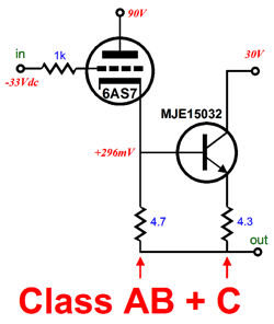
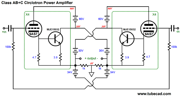
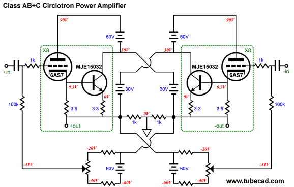
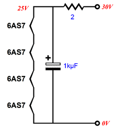
Here we see the class AB+C Circlotron power amplifier's naked output stage. A total of eight triodes and eight NPN transistors are used. The triodes see a B+ voltage of 90V at idle; the transistors, 30V. But as the transistors are turned off at idle, they should run fairly cool. The reason the transistors do not get 4.7-ohm emitter resistors is to bring there transconductance up a bit after a small initial emitter-follower loss. The two crisscrossed -34V power-supply rails provide the needed negative bias voltage for the 6AS7 triodes. They are crisscrossed to better null DC offsets, as the crisscrossing produces a garter-belt biasing effect. If one side goes too positive, the other side sees the increase in bias voltage as prompt to increase it output voltage more positively, while the too negative side's negative drift forces the other side to move away from being too positive. Very simple DC feedback that works well. Here is how it would be actually implemented.
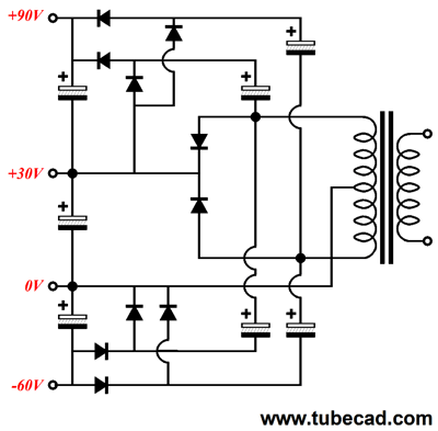
Note how -60V power-supply rails are used. Do not panic and falsely imagine that many power transformers are required. They are not. We can use just two 44Vac CT windings per channel with the following power supply circuit.
Sneaky, no? What is not shown is the heater power supply, which could consist of one massive 6.3Vac power transformer. Such a brute would have to deliver 2.5A of current per 6AS7 used. The sneakier approach would be to use DC to heat the 6AS7 heater elements. What? Yes, DC. If eight 6AS7 tubes (16 triodes) per channel, then we could string four heaters in series and use the 30Vdc power-supply rails to power the heater strings through a 2-ohm resistor. Thus, each channel would hold two heater strings, each holding four tube heaters.
By the way, we could go all-solid-state and use expensive and fancy lateral MOSFETs, such as the BUZ901.
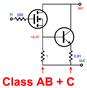
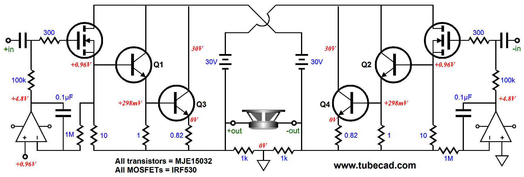
With such a pairing, the power supply becomes simple indeed, as two 30V floating rails are needed per channel. In the above example, the MOSFET idles at 300mA and the NPN transistor is cut off at idle. Once the MOSFET draws over 600mA, its partner transistor turns on, creating a constant-gm output. Why not use two MOSFETs? we certainly could.
Note the 40V power-supply rails, which would allow at least 60W of output into 8-ohm loads. Also note the relatively cheap IRF250 MOSFETs. The only problem with using MOSFETs throughout is getting the timing (the phasing of the turn on and turn off of the output devices) just right, as they do not have as fixed a turn-on voltage as NPN transistors do. Still, as the IRF250 is so cheap, we could buy a bunch and hand match them, which would make things a bit easier for us.
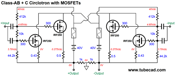
Note how the afterburner MOSFET overlap slightly with the primary class-AB MOSFETs. By the way, here is what just two IRF250 MOSFETs in the Circlotron look like.
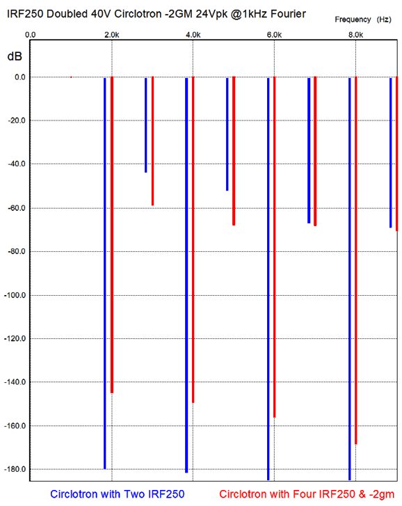
A peak voltage output of 24Vpk equals 36W (rms) into 8-ohm loads, which implies 3Apk of current flow, which the graph shows not to be the case. Interesting. I must have run the SPICE again with the same drive-voltage settings as in the -2gm version. In other words, this version is getting a small break. Nonetheless, note the gm doubling, where the two MOSFETs overlap in conduction. (The idle current was a truly hot 0.5A, so class-A operation extended out to 1A and 4W output.) Let's look at the distortion harmonics now.
I know which I would prefer to listen to, as the lower 3rd harmonic on the anti-2gm Circlotron with four output devices is much lower. By the way, some argue that MOSFETs are exempt from gm-doubling distortion. Well, the above graph belies such a conclusion. Okay, back to tubes. The two 30V power-supply rails limit the maximum output wattage into 8-ohm loads to about 40W. If more 6AS7 and MJE15032 pairs were used along with higher power-supply rail voltage, say 40Vdc to 55Vdc, then we could get much more power.

Class A + AB + C Circlotron Amplifier
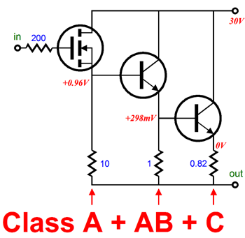
Or, something like this, if we went all-solid-state.
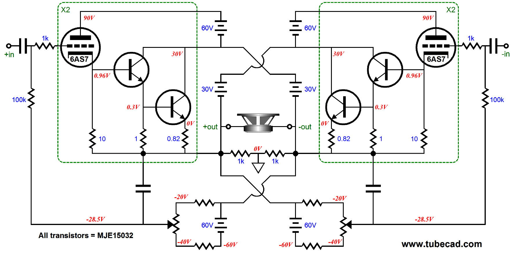
The advantage that the hybrid version offers is that tubes look cool. The advantage the all-solid-state version offers is lower distortion. Even with with all the help provided by the added transistors, the 6AS7 is not all that linear to start with and the resulting distortion is still relatively high. Here is the complete output stage.
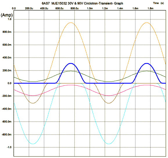
Only two 6AS7 are needed per channel (four triodes in other words). The following current plots from SPICE reveal that the 6AS7s never cutoff, even with 36W out into the 8-ohm load. (Green and red are the tube current plots.)
The above graph also shows how the class-AB and class-C transistors are timed correctly. The result is a constant-gm output stage. Of course we could scale up, using more 6AS7s and transistors and higher rail voltages, which could deliver lower distortion and much higher output wattages. On the other hand, the following design is cheap, simple, and effective.
The MOSFETs run in class-A and present a very high input impedance, which allows the simple DC servos to be used. The left DC servo sets the idle current, while the right DC servo sets the DC offset. The idle-current-setting DC servo only works because the MOSFET it controls runs in class-A. Had it run in class-AB, then the servo would over compensate during loud passages of music reproduction.
Next Time
*
User Guides for GlassWare Software Since I am still getting e-mail asking how to buy these GlassWare software programs:
For those of you who still have old computers running Windows XP (32-bit) or any other Windows 32-bit OS, I have setup the download availability of my old old standards: Tube CAD, SE Amp CAD, and Audio Gadgets. The downloads are at the GlassWare-Yahoo store and the price is only $9.95 for each program. http://glass-ware.stores.yahoo.net/adsoffromgla.html So many have asked that I had to do it. WARNING: THESE THREE PROGRAMS WILL NOT RUN UNDER VISTA 64-Bit or WINDOWS 7 & 8 or any other 64-bit OS. One day, I do plan on remaking all of these programs into 64-bit versions, but it will be a huge ordeal, as programming requires vast chunks of noise-free time, something very rare with children running about. Ideally, I would love to come out with versions that run on iPads and Android-OS tablets.
//JRB |
Kit User Guide PDFs
And
High-quality, double-sided, extra thick, 2-oz traces, plated-through holes, dual sets of resistor pads and pads for two coupling capacitors. Stereo and mono, octal and 9-pin printed circuit boards available.
Designed by John Broskie & Made in USA Aikido PCBs for as little as $24 http://glass-ware.stores.yahoo.net/
The Tube CAD Journal's first companion program, TCJ Filter Design lets you design a filter or crossover (passive, OpAmp or tube) without having to check out thick textbooks from the library and without having to breakout the scientific calculator. This program's goal is to provide a quick and easy display not only of the frequency response, but also of the resistor and capacitor values for a passive and active filters and crossovers. TCJ Filter Design is easy to use, but not lightweight, holding over 60 different filter topologies and up to four filter alignments: While the program's main concern is active filters, solid-state and tube, it also does passive filters. In fact, it can be used to calculate passive crossovers for use with speakers by entering 8 ohms as the terminating resistance. Click on the image below to see the full screen capture.
Tube crossovers are a major part of this program; both buffered and un-buffered tube based filters along with mono-polar and bipolar power supply topologies are covered. Available on a CD-ROM and a downloadable version (4 Megabytes). |
||


| www.tubecad.com Copyright © 1999-2015 GlassWare All Rights Reserved |